2000 YAMAHA TTR125 engine
[x] Cancel search: enginePage 26 of 442

CHAPTER 4
ENGINE
SEAT, FUEL TANK
AND SIDE COVERS
................................. 4-1
MUFFLER
................................................. 4-2
CARBURETOR
......................................... 4-3
CYLINDER HEAD
................................... 4-12
CAMSHAFT AND ROCKER ARMS
....... 4-20
VALVES AND VALVE SPRINGS
........... 4-24
CYLINDER AND PISTON
....................... 4-32
CLUTCH AND PRIMARY
DRIVEN GEAR
........................................ 4-40
OIL PUMP
............................................... 4-49
KICK AXLE AND SHIFT SHAFT
............ 4-53
CDI MAGNETO
....................................... 4-58
ENGINE REMOVAL
................................ 4-61
CRANKCASE, CRANKSHAFT
AND BALANCER
.................................... 4-65
TRANSMISSION, SHIFT CAM
AND SHIFT FORK
.................................. 4-73
CHAPTER 5
CHASSIS
FRONT WHEEL AND FRONT BRAKE
.... 5-1
REAR WHEEL AND REAR BRAKE
......... 5-8
FRONT FORK
......................................... 5-16
HANDLEBAR
.......................................... 5-25
STEERING
.............................................. 5-31
SWINGARM
............................................ 5-37
REAR SHOCK ABSORBER
................... 5-44
CHAPTER 6
ELECTRICAL
ELECTRICAL COMPONENTS
AND WIRING DIAGRAM
.......................... 6-1
IGNITION SYSTEM
................................... 6-2
Page 28 of 442

GEN
INFO
1 - 1
DESCRIPTION
EC100000
GENERAL INFORMATION
EC110000
DESCRIPTION
1
Clutch lever
2
Engine stop switch
3
Starter knob
4
Front brake lever
5
Throttle grip
6
Fuel tank cap
7
Air filter
8
Kickstarter crank
9
Fuel tank
0
Dipstick
A
Rear brake pedal
B
Fuel cock
C
Drive chain
D
Shift pedal
E
Front fork
NOTE:
l
The machine you have purchased may differ
slightly from those shown in the following.
l
Designs and specifications are subject to
change without notice.
1
1
Page 30 of 442

1 - 2
GEN
INFO
MACHINE IDENTIFICATION
EC120001
MACHINE IDENTIFICATION
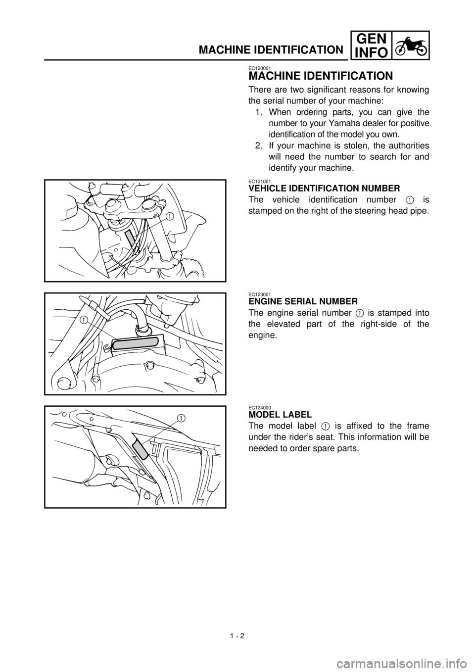
There are two significant reasons for knowing
the serial number of your machine:
1. When ordering parts, you can give the
number to your Yamaha dealer for positive
identification of the model you own.
2. If your machine is stolen, the authorities
will need the number to search for and
identify your machine.
EC121001
VEHICLE IDENTIFICATION NUMBER
The vehicle identification number
1
is
stamped on the right of the steering head pipe.
EC123001
ENGINE SERIAL NUMBER
The engine serial number
1
is stamped into
the elevated part of the right-side of the
engine.
EC124000
MODEL LABEL
The model label
1
is affixed to the frame
under the rider’s seat. This information will be
needed to order spare parts.
Page 34 of 442

1 - 4
GEN
INFO
IMPORTANT INFORMATION
EC133000
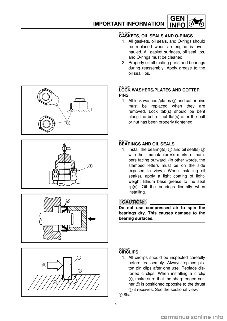
GASKETS, OIL SEALS AND O-RINGS
1. All gaskets, oil seals, and O-rings should
be replaced when an engine is over-
hauled. All gasket surfaces, oil seal lips,
and O-rings must be cleaned.
2. Properly oil all mating parts and bearings
during reassembly. Apply grease to the
oil seal lips.
EC134000
LOCK WASHERS/PLATES AND COTTER
PINS
1. All lock washers/plates
1
and cotter pins
must be replaced when they are
removed. Lock tab(s) should be bent
along the bolt or nut flat(s) after the bolt
or nut has been properly tightened.
EC135001
BEARINGS AND OIL SEALS
1. Install the bearing(s)
1
and oil seal(s)
2
with their manufacturer’s marks or num-
bers facing outward. (In other words, the
stamped letters must be on the side
exposed to view.) When installing oil
seal(s), apply a light coating of light-
weight lithium base grease to the seal
lip(s). Oil the bearings liberally when
installing.
CAUTION:
Do not use compressed air to spin the
bearings dry. This causes damage to the
bearing surfaces.
EC136000
CIRCLIPS
1. All circlips should be inspected carefully
before reassembly. Always replace pis-
ton pin clips after one use. Replace dis-
torted circlips. When installing a circlip
1
, make sure that the sharp-edged cor-
ner
2
is positioned opposite to the thrust
3
it receives. See the sectional view.
4
Shaft
Page 39 of 442

GEN
INFO
1 - 7
SPECIAL TOOLS
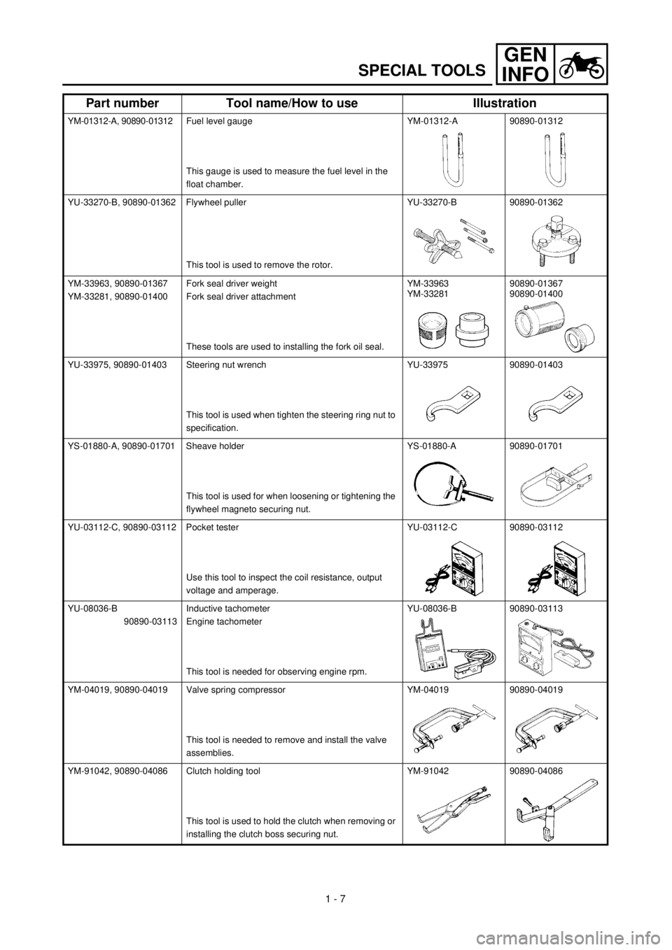
YM-01312-A, 90890-01312Fuel level gauge
This gauge is used to measure the fuel level in the
float chamber.YM-01312-A 90890-01312
YU-33270-B, 90890-01362 Flywheel puller
This tool is used to remove the rotor.YU-33270-B 90890-01362
YM-33963, 90890-01367
YM-33281, 90890-01400Fork seal driver weight
Fork seal driver attachment
These tools are used to installing the fork oil seal.YM-33963
YM-3328190890-01367
90890-01400
YU-33975, 90890-01403 Steering nut wrench
This tool is used when tighten the steering ring nut to
specification.YU-33975 90890-01403
YS-01880-A, 90890-01701 Sheave holder
This tool is used for when loosening or tightening the
flywheel magneto securing nut.YS-01880-A 90890-01701
YU-03112-C, 90890-03112 Pocket tester
Use this tool to inspect the coil resistance, output
voltage and amperage.YU-03112-C 90890-03112
YU-08036-B
90890-03113Inductive tachometer
Engine tachometer
This tool is needed for observing engine rpm.YU-08036-B 90890-03113
YM-04019, 90890-04019 Valve spring compressor
This tool is needed to remove and install the valve
assemblies.YM-04019 90890-04019
YM-91042, 90890-04086 Clutch holding tool
This tool is used to hold the clutch when removing or
installing the clutch boss securing nut.YM-91042 90890-04086
Part number Tool name/How to use Illustration
Page 48 of 442

1 - 9
GEN
INFO
CONTROL FUNCTIONS
EC150000
CONTROL FUNCTIONS
ENGINE STOP SWITCH
The engine stop switch 1 is located on the left
handlebar. Continue pushing the engine stop
switch till the engine comes to a stop.
EC152000
CLUTCH LEVER
The clutch lever 1 is located on the left han-
dlebar; it disengages or engages the clutch.
Pull the clutch lever to the handlebar to disen-
gage the clutch, and release the lever to
engage the clutch. The lever should be pulled
rapidly and released slowly for smooth starts.
EC153000
SHIFT PEDAL
The gear ratios of the constant-mesh 5 speed
transmission are ideally spaced. The gears
can be shifted by using the shift pedal 1 on
the left side of the engine.
KICKSTARTER CRANK
WARNING
Before starting the engine, be sure to shift
the transmission into neutral.
Rotate the kickstarter crank 1 away from the
engine. Push the starter down lightly with your
foot until the gears engage, then kick smoothly
and forcefully to start the engine.
EC155001
THROTTLE GRIP
The throttle grip 1 is located on the right han-
dlebar; it accelerates or decelerates the
engine. For acceleration, turn the grip toward
you; for deceleration, turn it away from you.
Page 49 of 442

GEN
INFOFONCTIONS DES COMMANDES
ARMATUREN UND DEREN FUNKTION
ARMATUREN UND DEREN FUNK-
TION
MOTORSTOPPSCHALTER “ENGINE STOP”
Der Motorstoppschalter “ENGINE STOP” 1
befindet sich auf der linken Seite des Lenkers.
Den Motorstoppschalter “ENGINE STOP” ge-
drückt halten, bis der Motor abstirbt.
KUPPLUNGSHEBEL
Der Kupplungshebel 1 befindet sich auf der lin-
ken Seite des Lenkers und dient zum Ein- und
Auskuppeln. Zum Ausrücken der Kupplung den
Kupplungshebel zum Lenkgriff ziehen; zum Ein-
rücken der Kupplung den Kupplungshebel wieder
freigeben. Zum Auskuppeln den Kupplungshebel
zügig ziehen, beim Einkuppeln gefühlvoll loslas-
sen, um ein weiches Einrücken der Kupplung zu
gewährleisten.
FUSSSCHALTHEBEL
Erst das Getriebe erlaubt die Nutzung der Mo-
torleistung in verschiedenen Geschwindig-
keitsbereichen, so daß Anfahren, Bergauffah-
ren und schnelles Beschleunigen möglich
sind. Die Gänge dieses 5-Gang-Getriebes
werden über den Fußschalthebel 1 linksseitig
des Motors bei ausgerückter Kupplung ge-
schaltet.
KICKSTARTERKURBEL
WARNUNG
Vor dem Anlassen des Motors sicherstel-
len, daß sich das Getriebe in der Leerlauf-
stellung befindet.
Zum Anlassen des Motors den Kickstarter-
hebel 1 ausschwenken und langsam nieder-
treten, bis deutlicher Widerstand spürbar
wird; dann den Kickstarterhebel schwungvoll
durchtreten.
GASDREHGRIFF
Der Gasdrehgriff 1 befindet sich auf der rech-
ten Seite des Lenkers. Zum Erhöhen der Mo-
tordrehzahl (Beschleunigung) den Gasdreh-
griff in Gegenfahrtrichtung drehen, zum
Reduzieren der Motordrehzahl den Gasdreh-
griff in Fahrtrichtung drehen.
FONCTIONS DES COMMANDES
COUPE-CIRCUIT DU MOTEUR
Le coupe-circuit du moteur 1 se trouve à la poi-
gnée gauche. Appuyer sur le coupe-circuit du
moteur jusqu’à ce que le moteur se coupe.
LEVIER D’EMBRAYAGE
Le levier d’embrayage 1 se trouve à la poignée
gauche. Celui-ci permet d’embrayer et de débrayer
le moteur. Tirer le levier d’embrayage vers la poi-
gnée pour débrayer et relâcher le levier pour
embrayer le moteur. Un fonctionnement en dou-
ceur s’obtient en tirant le levier rapidement et en le
relâchant lentement.
PÉDALE DE SÉLECTION
Les 5 rapports de la boîte de vitesses à prise cons-
tante sont idéalement échelonnés. Le changement
de vitesse est commandé par la pédale de sélection
1, situé du côté gauche du moteur.
PÉDALE DE KICK
AVERTISSEMENT
Avant de mettre le moteur en marche, veiller à
ce que le véhicule soit au point mort.
Déployer la pédale de kick 1. Appuyer légèrement
sur la pédale pour mettre les pignons en prise, puis
l’actionner vigoureusement mais en souplesse pour
mettre le moteur en marche.
POIGNÉE DES GAZ
La poignée des gaz 1 se trouve à la poignée droite
et permet d’accélérer ou de décélérer. Pour accélé-
rer, tourner la poignée vers soi et pour décélérer, la
tourner de l’autre côté.
1 - 9
Page 50 of 442

1 - 10
GEN
INFO
CONTROL FUNCTIONS
EC156000
FRONT BRAKE LEVER
The front brake lever 1 is located on the right
handlebar. Pull it toward the handlebar to acti-
vate the front brake.
EC157000
REAR BRAKE PEDAL
The rear brake pedal 1 is located on the right
side of the machine. Press down on the brake
pedal to activate the rear brake.
EC158010
FUEL COCK
The fuel cock supplies fuel from the tank to
carburetor while filtering the fuel. The fuel cock
has the three positions:
OFF: With the lever in this position, fuel will
not flow. Always return the lever to this
position when the engine is not running.
ON: With the lever in this position, fuel flows
to the carburetor. Normal riding is done
with the lever in this position.
RES: This indicates reserve. If you run out of
fuel while riding, move the lever to this
position. FILL THE TANK AT THE
FIRST OPPORTUNITY. BE SURE TO
SET THE LEVER TO “ON” AFTER
REFUELING.
EC159000
STARTER KNOB (CHOKE)
When cold, the engine requires a richer air-fuel
mixture for starting. A separate starter circuit,
which is controlled by the starter knob 1, sup-
plies this mixture. Pull the starter knob out to
open the circuit for starting. When the engine
has warmed up, push it in to close the circuit.