2000 YAMAHA TDR 125 engine
[x] Cancel search: enginePage 80 of 104
6-35
PERIODIC MAINTENANCE AND MINOR REPAIR
1
2
3
4
5
6
7
8
9
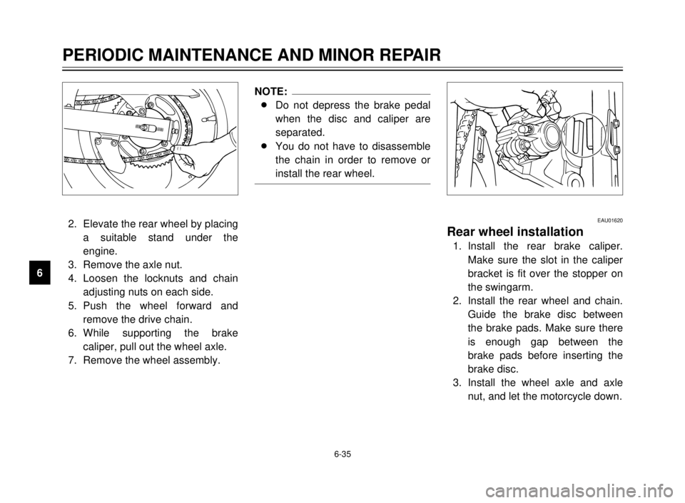
2. Elevate the rear wheel by placing
a suitable stand under the
engine.
3. Remove the axle nut.
4. Loosen the locknuts and chain
adjusting nuts on each side.
5. Push the wheel forward and
remove the drive chain.
6. While supporting the brake
caliper, pull out the wheel axle.
7. Remove the wheel assembly.
NOTE:
8Do not depress the brake pedal
when the disc and caliper are
separated.
8You do not have to disassemble
the chain in order to remove or
install the rear wheel.
EAU01620
Rear wheel installation
1. Install the rear brake caliper.
Make sure the slot in the caliper
bracket is fit over the stopper on
the swingarm.
2. Install the rear wheel and chain.
Guide the brake disc between
the brake pads. Make sure there
is enough gap between the
brake pads before inserting the
brake disc.
3. Install the wheel axle and axle
nut, and let the motorcycle down.
5AE-9-E3 (ENG) 4/11/0 11:06 AM Page 78
Page 82 of 104
6-37
PERIODIC MAINTENANCE AND MINOR REPAIR
1
2
3
4
5
6
7
8
9
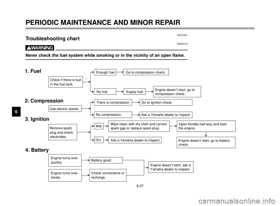
EAU01581Troubleshooting chartEW000125
w
Never check the fuel system while smoking or in the vicinity of an open flame.
1. Fuel
2. Compression
3. Ignition
4. Battery
Use electric starter.
Remove spark
There is compression.
Go to ignition check.
No compression.
Ask a Yamaha dealer to inspect.
Wet.
Dry.Wipe clean with dry cloth and correct
Open throttle half-way and start
Ask a Yamaha dealer to inspect.
Check if there is fuel
Enough fuel.
No fuel.Go to compression check.
Supply fuel.
in the fuel tank.
electrodes. plug and check
Engine doesn’t start, go to battery
check. the engine. spark gap or replace spark plug.
Engine turns over
Engine turns overBattery good.
Check connections or
quickly.
slowly. recharge.Engine doesn’t start, ask aYamaha dealer to inspect.
Engine doesn’t start, go to compression check.
5AE-9-E3 (ENG) 4/11/0 11:06 AM Page 80
Page 83 of 104

6-38
PERIODIC MAINTENANCE AND MINOR REPAIR
1
2
3
4
5
6
7
8
9
5. Engine overheating
w
Do not remove the radiator cap when the engine and radiator are hot. Scalding hot fluid and steam may be
blown out under pressure, which could cause serious injury. Open the radiator cap as follows. Wait until the
engine has cooled. Remove the radiator cap stopper by removing the screw. Place a thick rag like a towel over
the radiator cap and slowly rotate the cap counterclockwise to the detent. This procedure allows any residual
pressure to escape. When the hissing sound has stopped, press down on the cap while turning counterclock-
wise and remove it.
NOTE:
If it is difficult to get the recommended coolant, tap water can be temporarily used, provided that it is changed to the rec-
ommended coolant as soon as possible.
Level is OK.
Wait until the engine
has cooled.
Restart the engine. If the engine overheats again, ask a
Yamaha dealer to inspect and repair the cooling system. Check the coolant level in the
reservoir tank and/or radiator.
Add coolant (See NOTE.)
Level is low, check thecooling system for leakage.Leakage.No
leakage.Ask a Yamaha dealer to inspect
and repair the cooling system.
5AE-9-E3 (ENG) 4/11/0 11:06 AM Page 81
Page 87 of 104
1
2
3
4
5
6
7
8
9
7-2
8 8
Improper cleaning can damage
windshields, cowlings, panels
and other plastic parts. Use
only a soft, clean cloth or
sponge with mild detergent
and water to clean plastic.
8 8
Do not use any harsh chemical
products on plastic parts. Be
sure to avoid using cloths or
sponges which have been in
contact with strong or abra-
sive cleaning products, sol-
vent or thinner, fuel (gasoline),
rust removers or inhibitors,
brake fluid, antifreeze or elec-
trolyte.8 8
Do not use high-pressure
washers or steam-jet cleaners
since they cause water seep-
age and deterioration in the
following areas: seals (of
wheel bearings, swingarm
bearings, forks and brakes),
electric components (cou-
plers, connectors, instru-
ments, switches and lights),
breather hoses and vents.
8 8
For motorcycles equipped
with a windshield: Do not use
strong cleaners or hard
sponges as they will cause
dulling or scratching. Some
cleaning compounds for plas-
tic may leave scratches on the
windshield. Test the product
on a small hidden part of the
windshield to make sure they
do not leave any marks. If the
windshield is scratched, use a
quality plastic polishing com-
pound after washing.After riding in the rain, near the sea
or on salt-sprayed roads
Since sea salt or salt sprayed on the
roads in the winter are extremely cor-
rosive in combination with water,
carry out the following steps after
each ride in the rain, near the sea or
on salt-sprayed roads. (Salt sprayed
in the winter may remain on the roads
well into spring.)
1. Clean your motorcycle with cold
water and soap after the engine
has cooled down.
ECA00012
cC
Do not use warm water since it
increases the corrosive action of
the salt.
2. Be sure to apply a corrosion pro-
tection spray on all (even
chrome- and nickel-plated) metal
surfaces to prevent corrosion.
MOTORCYCLE CARE AND STORAGE
7
5AE-9-E3 (ENG) 4/11/0 11:06 AM Page 85
Page 89 of 104
1
2
3
4
5
6
7
8
9
7-4
Storage
Short-term
Always store your motorcycle in a
cool, dry place and, if necessary, pro-
tect it against dust with a porous
cover.
ECA00014
cC
8
8
Storing the motorcycle in a
poorly ventilated room or cov-
ering it with a tarp while it is
still wet will allow water and
humidity to seep in and cause
rust.
8 8
To prevent corrosion, avoid
damp cellars, stables (because
of the presence of ammonia)
and areas where strong chemi-
cals are stored.
Long-term
Before storing your motorcycle for
several months:
1. Follow all the instructions in the
“Care” section of this chapter.
2. Drain the carburetor float cham-
ber by loosening the drain bolt;
this will prevent fuel deposits
from building up. Pour the
drained fuel into the fuel tank.
3. Only for motorcycles equipped
with a fuel cock which has an
“OFF” position: Turn the fuel
cock to “OFF”.
4. Fill up the fuel tank and add fuel
stabilizer (if available) to prevent
the fuel tank from rusting and the
fuel from deteriorating.
5. Perform the following steps to
protect the cylinder, piston rings,
etc. from corrosion.a. Remove the spark plug cap and
spark plug.
b. Pour a teaspoonful of engine oil
into the spark plug bore.
c. Install the spark plug cap onto
the spark plug and place the
spark plug on the cylinder head
so that the electrodes are
grounded. (This will limit spark-
ing during the next step.)
d. Turn the engine over several
times with the starter. (This will
coat the cylinder wall with oil.)
e. Remove the spark plug cap from
the spark plug, install the spark
plug and then the spark plug
cap.
EWA00003
w
When turning the engine over, be
sure to ground the spark plug elec-
trodes to prevent damage or injury
from sparking.
MOTORCYCLE CARE AND STORAGE
7
5AE-9-E3 (ENG) 4/11/0 11:06 AM Page 87
Page 92 of 104
SPECIFICATIONS
1
2
3
4
5
6
7
8
9
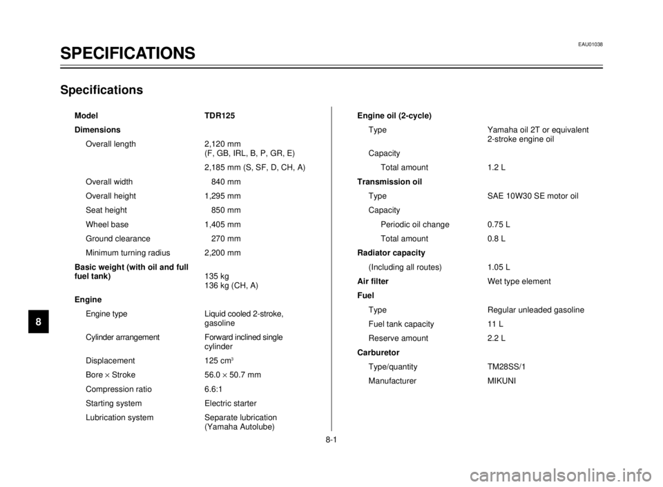
Specifications
Model TDR125
Dimensions
Overall length 2,120 mm
(F, GB, IRL, B, P, GR, E)
2,185 mm (S, SF, D, CH, A)
Overall width 840 mm
Overall height 1,295 mm
Seat height 850 mm
Wheel base 1,405 mm
Ground clearance 270 mm
Minimum turning radius 2,200 mm
Basic weight (with oil and full
fuel tank)135 kg
136 kg (CH, A)
Engine
Engine type Liquid cooled 2-stroke,
gasoline
Cylinder arrangement Forward inclined single
cylinder
Displacement 125 cm
3
Bore ´Stroke 56.0 ´50.7 mm
Compression ratio 6.6:1
Starting system Electric starter
Lubrication system Separate lubrication
(Yamaha Autolube)Engine oil (2-cycle)
Type Yamaha oil 2T or equivalent
2-stroke engine oil
Capacity
Total amount 1.2 L
Transmission oil
Type SAE 10W30 SE motor oil
Capacity
Periodic oil change 0.75 L
Total amount 0.8 L
Radiator capacity
(Including all routes) 1.05 L
Air filterWet type element
Fuel
Type Regular unleaded gasoline
Fuel tank capacity 11 L
Reserve amount 2.2 L
Carburetor
Type/quantity TM28SS/1
Manufacturer MIKUNI
EAU01038
SPECIFICATIONS
8-1
5AE-9-E3 (ENG) 4/11/0 11:06 AM Page 90
Page 100 of 104
INDEX
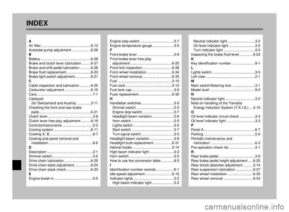
Engine stop switch ..................................3-7
Engine temperature gauge ......................3-5
F
Front brake lever .....................................3-8
Front brake lever free play
adjustment ..........................................6-20
Front fork inspection ..............................6-28
Front wheel installation..........................6-34
Front wheel removal ..............................6-33
Fuel .......................................................3-10
Fuel cock ...............................................3-12
Fuel tank cap ...........................................3-9
Fuse replacement..................................6-30
H
Handlebar switches .................................3-5
Dimmer switch ......................................3-5
Engine stop switch ................................3-7
Headlight beam variation ......................3-6
Horn switch ...........................................3-5
Lights switch .........................................3-5
Start switch ...........................................3-7
Turn signal switch .................................3-5
Headlight beam variation.........................3-6
Headlight bulb replacement...................6-31
Helmet holder ........................................3-14
High beam indicator light .........................3-2
Horn switch..............................................3-5
How to use the conversion table .............8-5
I
Identification number records ..................9-1
Idle speed adjustment ...........................6-15
Indicator lights .........................................3-2
High beam indicator light ......................3-2Neutral indicator light ............................3-2
Oil level indicator light ...........................3-2
Turn indicator light ................................3-2
Inspecting the brake fluid level ..............6-22
K
Key identification number ........................9-1
L
Lights switch ............................................3-5
Left view ..................................................2-1
M
Main switch/Steering lock ........................3-1
Model lavel ..............................................9-2
N
Neutral indicator light...............................3-2
Note on handling of the Yamaha
Energy Induction System (Y.E.I.S.) ....3-15
O
Oil level indicator circuit check ................3-3
Oil level indicator light .............................3-2
P
Panel A ....................................................6-7
Parking ....................................................5-6
Periodic maintenance and
lubrication .............................................6-3
Pre-operation check list ...........................4-1
R
Rear brake pedal .....................................3-9
Rear brake pedal height adjustment .....6-20
Rear shock absorber adjustment ..........3-14
Rear suspension lubrication ..................6-27
Rear wheel installation ..........................6-35
Rear wheel removal ..............................6-34A
Air filter ..................................................6-13
Autolube pump adjustment....................6-26
B
Battery ...................................................6-29
Brake and clutch lever lubrication .........6-27
Brake and shift pedal lubrication ...........6-26
Brake fluid replacement.........................6-23
Brake light switch adjustment ................6-21
C
Cable inspection and lubrication ...........6-25
Carburetor adjustment...........................6-15
Care.........................................................7-1
Catalyzer
(for Switzerland and Austria) ..............3-11
Checking the front and rear brake
pads ....................................................6-21
Clutch lever .............................................3-8
Clutch lever free play adjustment ..........6-19
Controls/Instruments ...............................2-3
Cooling system ......................................6-11
Cowling A, B ............................................6-7
Cowling and panel removal and
installation .............................................6-6
D
Description ..............................................2-1
Dimmer switch .........................................3-5
Drive chain lubrication ...........................6-25
Drive chain slack adjustment.................6-24
Drive chain slack check .........................6-23
E
Engine break-in .......................................5-5
5AE-9-E3 (ENG) 4/11/0 11:06 AM Page 98
Page 101 of 104
INDEX
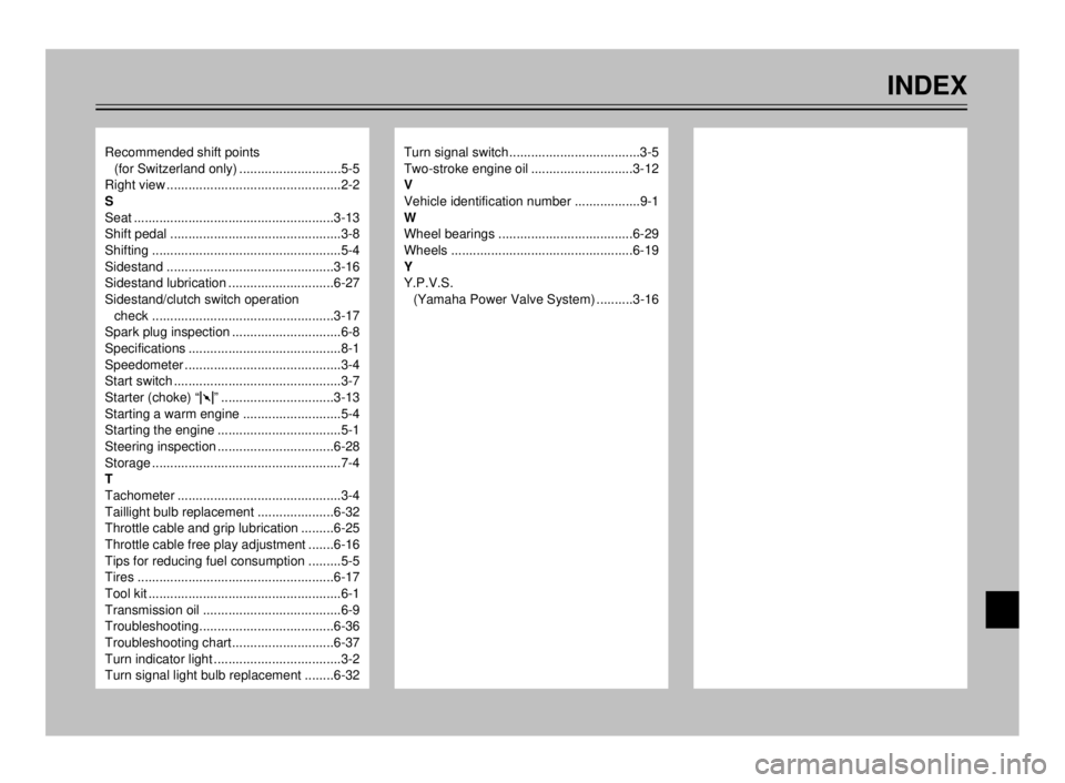
Recommended shift points
(for Switzerland only) ............................5-5
Right view ................................................2-2
S
Seat .......................................................3-13
Shift pedal ...............................................3-8
Shifting ....................................................5-4
Sidestand ..............................................3-16
Sidestand lubrication .............................6-27
Sidestand/clutch switch operation
check ..................................................3-17
Spark plug inspection ..............................6-8
Specifications ..........................................8-1
Speedometer ...........................................3-4
Start switch ..............................................3-7
Starter (choke) “1” ...............................3-13
Starting a warm engine ...........................5-4
Starting the engine ..................................5-1
Steering inspection ................................6-28
Storage ....................................................7-4
T
Tachometer .............................................3-4
Taillight bulb replacement .....................6-32
Throttle cable and grip lubrication .........6-25
Throttle cable free play adjustment .......6-16
Tips for reducing fuel consumption .........5-5
Tires ......................................................6-17
Tool kit .....................................................6-1
Transmission oil ......................................6-9
Troubleshooting.....................................6-36
Troubleshooting chart............................6-37
Turn indicator light ...................................3-2
Turn signal light bulb replacement ........6-32Turn signal switch....................................3-5
Two-stroke engine oil ............................3-12
V
Vehicle identification number ..................9-1
W
Wheel bearings .....................................6-29
Wheels ..................................................6-19
Y
Y.P.V.S.
(Yamaha Power Valve System) ..........3-16
5AE-9-E3 (ENG) 4/11/0 11:06 AM Page 99