2000 YAMAHA TDR 125 headlight bulb
[x] Cancel search: headlight bulbPage 21 of 104
3-6
INSTRUMENT AND CONTROL FUNCTIONS
1
2
3
4
5
6
7
8
9
1
2&
&%
%
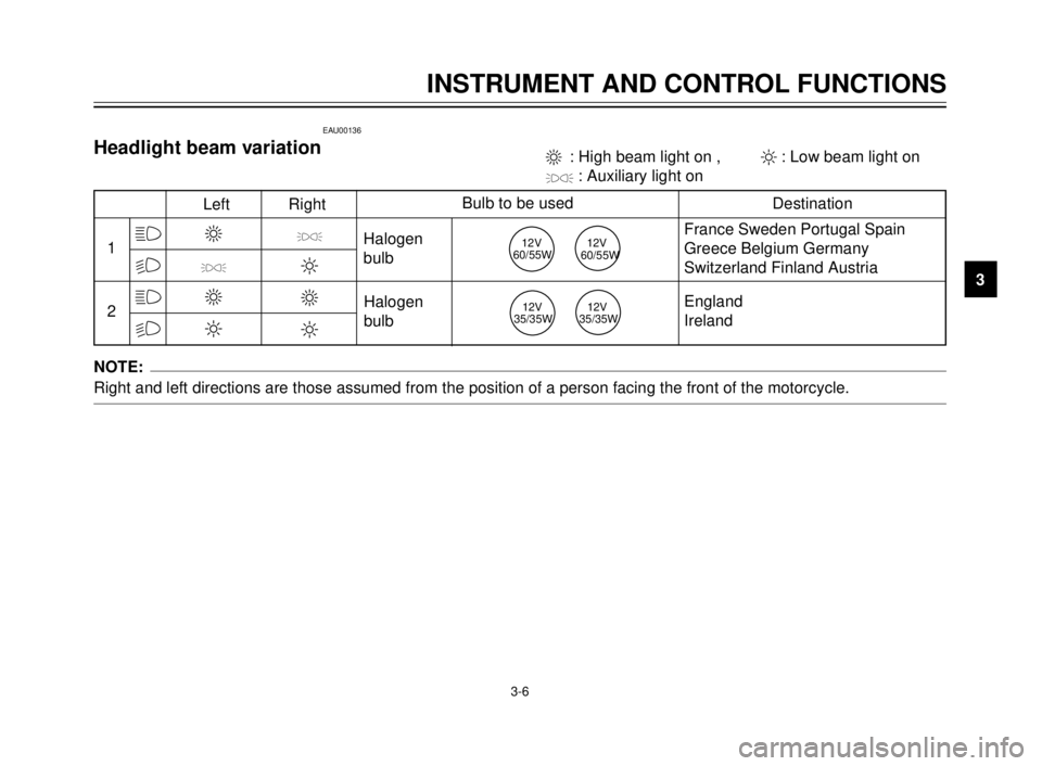
Left RightBulb to be used
Destination
3
'
3
2
'
2
3
2
Halogen
bulb
Halogen
bulbFrance Sweden Portugal Spain
Greece Belgium Germany
Switzerland Finland Austria
England
Ireland 3 : High beam light on , 2: Low beam light on
': Auxiliary light on
12V
60/55W12V
60/55W
12V
35/35W12V
35/35W
EAU00136
Headlight beam variation
NOTE:
Right and left directions are those assumed from the position of a person facing the front of the motorcycle.
5AE-9-E3 (ENG) 4/11/0 11:06 AM Page 19
Page 45 of 104
PERIODIC MAINTENANCE AND MINOR REPAIR
Tool kit ...................................................................6-1
Periodic maintenance and lubrication ....................6-3
Cowling and panel removal and installation...........6-6
Cowling A, B ..........................................................6-7
Panel A ..................................................................6-7
Spark plug inspection.............................................6-8
Transmission oil .....................................................6-9
Cooling system ....................................................6-10
Changing the coolant ...........................................6-11
Air filter .................................................................6-13
Carburetor adjustment .........................................6-15
Idle speed adjustment ..........................................6-15
Throttle cable free play adjustment ......................6-16
Tires .....................................................................6-17
Wheels .................................................................6-19
Clutch lever free play adjustment.........................6-19
Front brake lever free play adjustment ................6-20
Rear brake pedal height adjustment ....................6-20
Brake light switch adjustment ..............................6-21
Checking the front and rear brake pads...............6-21
Inspecting the brake fluid level.............................6-22
Brake fluid replacement .......................................6-23
Drive chain slack check .......................................6-23
Drive chain slack adjustment ...............................6-24Drive chain lubrication............................................6-25
Cable inspection and lubrication ............................6-25
Throttle cable and grip lubrication ..........................6-26
Autolube pump adjustment ....................................6-26
Brake and shift pedal lubrication ............................6-26
Brake and clutch lever lubrication ..........................6-27
Sidestand lubrication..............................................6-27
Rear suspension lubrication...................................6-27
Front fork inspection ..............................................6-28
Steering inspection ................................................6-28
Wheel bearings ......................................................6-29
Battery....................................................................6-29
Fuse replacement ..................................................6-30
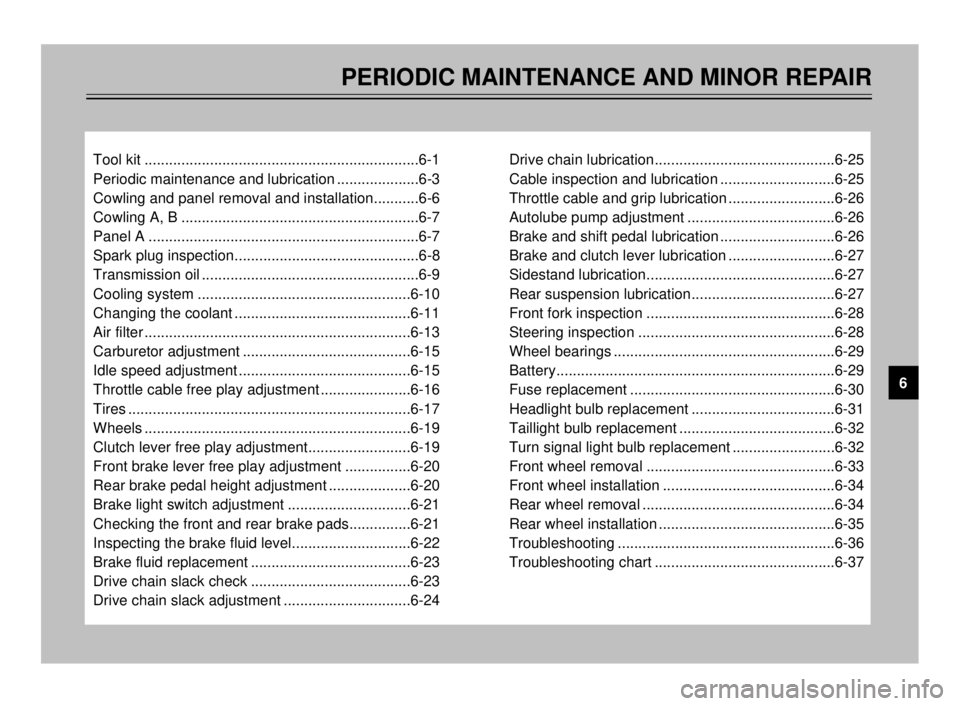
Headlight bulb replacement ...................................6-31
Taillight bulb replacement ......................................6-32
Turn signal light bulb replacement .........................6-32
Front wheel removal ..............................................6-33
Front wheel installation ..........................................6-34
Rear wheel removal ...............................................6-34
Rear wheel installation ...........................................6-35
Troubleshooting .....................................................6-36
Troubleshooting chart ............................................6-37
6
5AE-9-E3 (ENG) 4/11/0 11:06 AM Page 43
Page 76 of 104
6-31
PERIODIC MAINTENANCE AND MINOR REPAIR
1
2
3
4
5
6
7
8
9
2
1
2
1
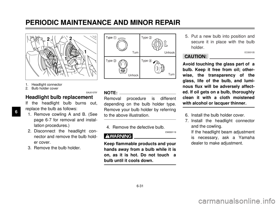
1. Headlight connector
2. Bulb holder cover
EAU01079*
Headlight bulb replacement
If the headlight bulb burns out,
replace the bulb as follows:
1. Remove cowling A and B. (See
page 6-7 for removal and instal-
lation procedures.)
2. Disconnect the headlight con-
nector and remove the bulb hold-
er cover.
3. Remove the bulb holder.
NOTE:
Removal procedure is different
depending on the bulb holder type.
Remove your bulb holder by referring
to the above illustration.
4. Remove the defective bulb.EW000119
w
Keep flammable products and your
hands away from a bulb while it is
on, as it is hot. Do not touch a
bulb until it cools down.
Type 1Type 2
Type 3Type 4 Turn
Unhook
UnhockTurn5. Put a new bulb into position and
secure it in place with the bulb
holder.
EC000105
cC
Avoid touching the glass part of a
bulb. Keep it free from oil; other-
wise, the transparency of the
glass, life of the bulb, and lumi-
nous flux will be adversely affect-
ed. If oil gets on a bulb, thoroughly
clean it with a cloth moistened
with alcohol or lacquer thinner.
6. Install the bulb holder cover.
7. Install the headlight connector
and the cowling.
If the headlight beam adjustment
is necessary, ask a Yamaha
dealer to make adjustment.
5AE-9-E3 (ENG) 4/11/0 11:06 AM Page 74
Page 94 of 104
SPECIFICATIONS
1
2
3
4
5
6
7
8
9
Wheels
Front
Type Cast wheel
Size 18 ´MT2.15
Rear
Type Cast wheel
Size 17 ´MT2.50
Brakes
Front
Type Single disc brake
Operation Right hand operation
Fluid DOT 3 or DOT 4
Rear
Type Single disc brake
Operation Right foot operation
Fluid DOT 4
Suspension
Front
Type Telescopic fork
Rear
Type Swingarm (Monocross)Shock absorber
Front
Type Coil spring/oil damper
Rear
Type Coil-gas spring/oil damper
Wheel travel
Front 180 mm
Rear 180 mm
Electrical
Ignition system C.D.I.
Charging system
Type C.D.I. magneto
Standard output 14 V, 12A @5,000 r/min
Battery
Type YTX5L-BS
Voltage, capacity 12 V, 4 AH
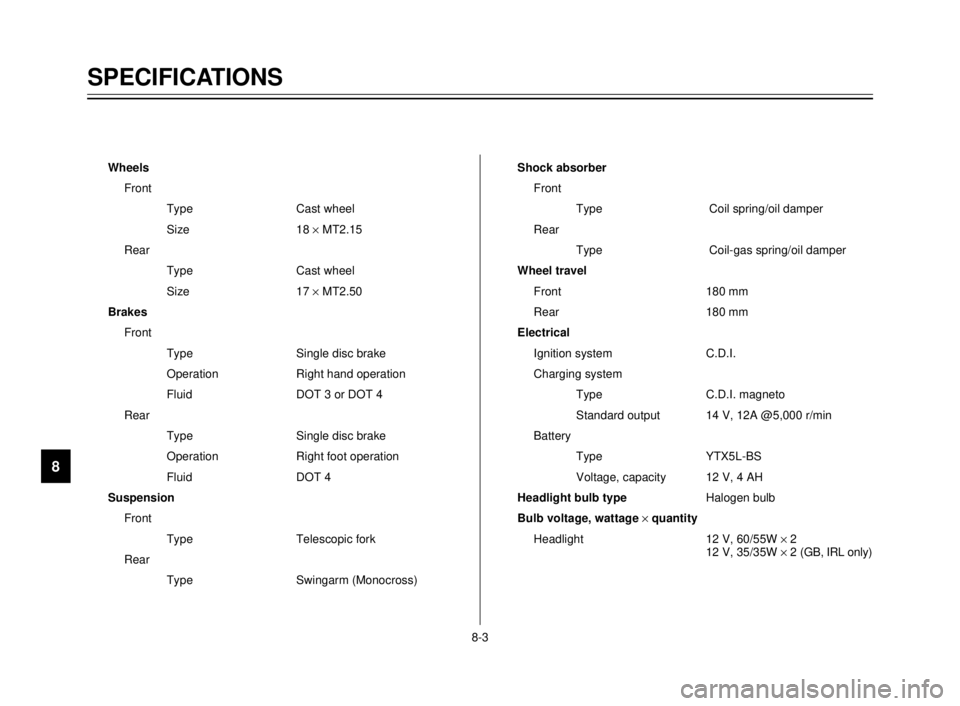
Headlight bulb typeHalogen bulb
Bulb voltage, wattage ´quantity
Headlight 12 V, 60/55W ´2
12 V, 35/35W ´2 (GB, IRL only)
8-3
5AE-9-E3 (ENG) 4/11/0 11:06 AM Page 92
Page 100 of 104
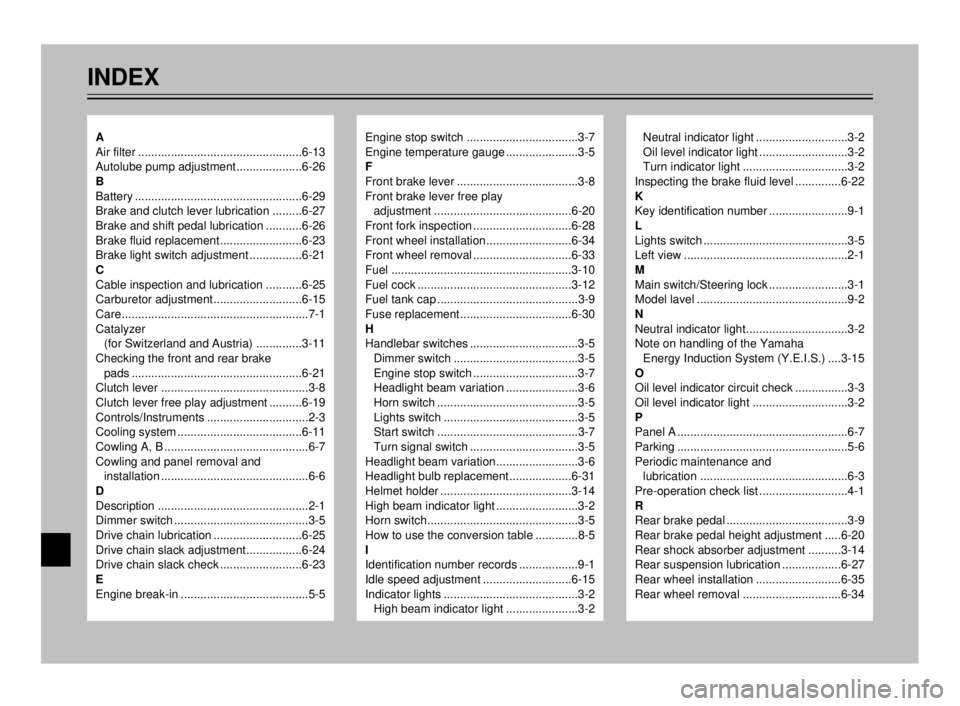
INDEX
Engine stop switch ..................................3-7
Engine temperature gauge ......................3-5
F
Front brake lever .....................................3-8
Front brake lever free play
adjustment ..........................................6-20
Front fork inspection ..............................6-28
Front wheel installation..........................6-34
Front wheel removal ..............................6-33
Fuel .......................................................3-10
Fuel cock ...............................................3-12
Fuel tank cap ...........................................3-9
Fuse replacement..................................6-30
H
Handlebar switches .................................3-5
Dimmer switch ......................................3-5
Engine stop switch ................................3-7
Headlight beam variation ......................3-6
Horn switch ...........................................3-5
Lights switch .........................................3-5
Start switch ...........................................3-7
Turn signal switch .................................3-5
Headlight beam variation.........................3-6
Headlight bulb replacement...................6-31
Helmet holder ........................................3-14
High beam indicator light .........................3-2
Horn switch..............................................3-5
How to use the conversion table .............8-5
I
Identification number records ..................9-1
Idle speed adjustment ...........................6-15
Indicator lights .........................................3-2
High beam indicator light ......................3-2Neutral indicator light ............................3-2
Oil level indicator light ...........................3-2
Turn indicator light ................................3-2
Inspecting the brake fluid level ..............6-22
K
Key identification number ........................9-1
L
Lights switch ............................................3-5
Left view ..................................................2-1
M
Main switch/Steering lock ........................3-1
Model lavel ..............................................9-2
N
Neutral indicator light...............................3-2
Note on handling of the Yamaha
Energy Induction System (Y.E.I.S.) ....3-15
O
Oil level indicator circuit check ................3-3
Oil level indicator light .............................3-2
P
Panel A ....................................................6-7
Parking ....................................................5-6
Periodic maintenance and
lubrication .............................................6-3
Pre-operation check list ...........................4-1
R
Rear brake pedal .....................................3-9
Rear brake pedal height adjustment .....6-20
Rear shock absorber adjustment ..........3-14
Rear suspension lubrication ..................6-27
Rear wheel installation ..........................6-35
Rear wheel removal ..............................6-34A
Air filter ..................................................6-13
Autolube pump adjustment....................6-26
B
Battery ...................................................6-29
Brake and clutch lever lubrication .........6-27
Brake and shift pedal lubrication ...........6-26
Brake fluid replacement.........................6-23
Brake light switch adjustment ................6-21
C
Cable inspection and lubrication ...........6-25
Carburetor adjustment...........................6-15
Care.........................................................7-1
Catalyzer
(for Switzerland and Austria) ..............3-11
Checking the front and rear brake
pads ....................................................6-21
Clutch lever .............................................3-8
Clutch lever free play adjustment ..........6-19
Controls/Instruments ...............................2-3
Cooling system ......................................6-11
Cowling A, B ............................................6-7
Cowling and panel removal and
installation .............................................6-6
D
Description ..............................................2-1
Dimmer switch .........................................3-5
Drive chain lubrication ...........................6-25
Drive chain slack adjustment.................6-24
Drive chain slack check .........................6-23
E
Engine break-in .......................................5-5
5AE-9-E3 (ENG) 4/11/0 11:06 AM Page 98