Page 25 of 99

INSTRUMENT AND CONTROL FUNCTIONS
3-11
3
EAU01183
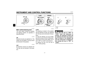
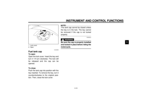
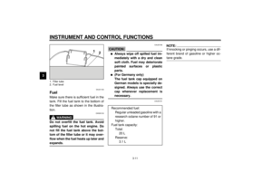
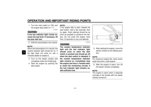
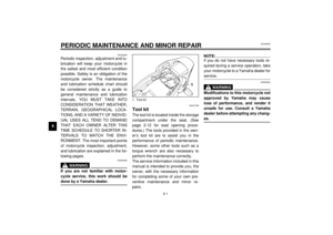
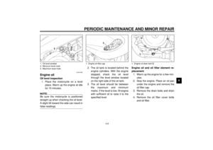
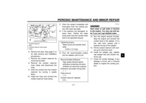
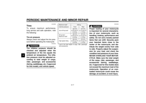
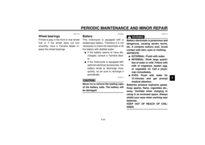
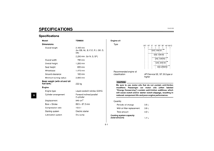
FuelMake sure there is sufficient fuel in the
tank. Fill the fuel tank to the bottom of
the filler tube as shown in the illustra-
tion.
EW000130
WARNING
@ Do not overfill the fuel tank. Avoid
spilling fuel on the hot engine. Do
not fill the fuel tank above the bot-
tom of the filler tube or it may over-
flow when the fuel heats up later and
expands. @
EAU00186
CAUTION:@ l
Always wipe off spilled fuel im-
mediately with a dry and clean
soft cloth. Fuel may deteriorate
painted surfaces or plastic
parts.
l
(For Germany only)
The fuel tank cap equipped on
German models is specially de-
signed. Always use the correct
cap whenever replacement is
necessary.
@
EAU00191
NOTE:@ If knocking or pinging occurs, use a dif-
ferent brand of gasoline or higher oc-
tane grade. @
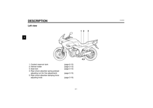
1. Filler tube
2. Fuel level
Recommended fuel:
Regular unleaded gasoline with a
research octane number of 91 or
higher.
Fuel tank capacity:
Total:
20 L
Reserve:
3.1 L
E_4tx_Functions.fm Page 11 Saturday, October 16, 1999 9:36 AM
Page 26 of 99
INSTRUMENT AND CONTROL FUNCTIONS
3-12
3
EAU00196
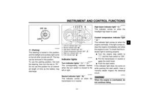
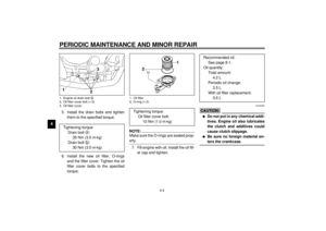
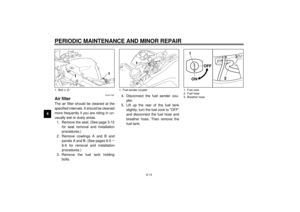
Fuel tank breather hose
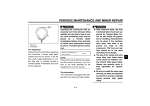
(for Germany only)This model is equipped with a fuel tank
breather hose. Before using this motor-
cycle, be sure to:l
Check hose connection.
l
Check hose for cracks or damage.
Replace if damaged.
l
Make sure the end of the hose is
not blocked. Clean it if necessary.
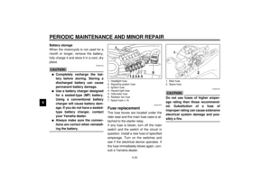
EAU01726
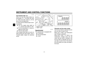
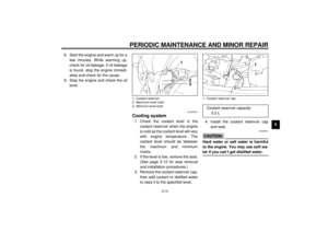
SeatTo remove
Insert the key in the lock and turn it
clockwise.To install
Insert the projections on the front of the
seat into the seat holders. Then push
down on the seat.
NOTE:@ Make sure that the seat is securely fit-
ted. @
1. Fuel tank breather hose
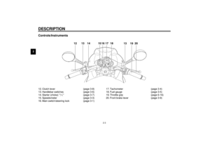
1. Open
1. Projection (´ 2)
2. Seat holder (´ 2)
E_4tx_Functions.fm Page 12 Saturday, October 16, 1999 9:36 AM
Page 27 of 99

INSTRUMENT AND CONTROL FUNCTIONS
3-13
3
EAU00263
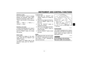
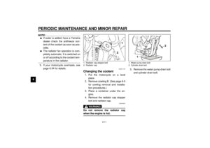
Helmet holderThe helmet holder is under the seat.
Remove the seat and hook the helmet
on the helmet holder. Then, reinstall
the seat and lock it.
EW000030
WARNING
@ Never ride with a helmet in the hel-
met holder. The helmet may hit ob-
jects, causing loss of control and
possibly an accident. @
EAU01688
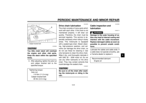
Storage compartmentThis compartment is designed to store
a genuine Yamaha U-LOCK. (Other
locks may not fit.)
Be sure the lock is fastened securely
with the straps when storing it in the
compartment.
To prevent losing the straps, be sure to
secure them even when a U-LOCK is
not being stored in the compartment.When storing this Owner’s manual or
other documents in the compartment,
be sure to put them in a vinyl bag so
they do not get wet. When washing the
motorcycle, be careful not to flood this
compartment with water.
1. Helmet holder
1. U-LOCK (optional)
2. Strap
1. U-LOCK (optional)
2. Strap (´ 2)
E_4tx_Functions.fm Page 13 Saturday, October 16, 1999 9:36 AM
Page 28 of 99

INSTRUMENT AND CONTROL FUNCTIONS
3-14
3
EAU01728
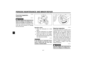
Front fork adjustmentThe front fork is equipped with spring
preload and damping force adjusters.
EW000038
WARNING
@ Always adjust each fork leg to the
same setting. Uneven adjustment
can cause poor handling and loss of
stability. @
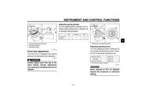
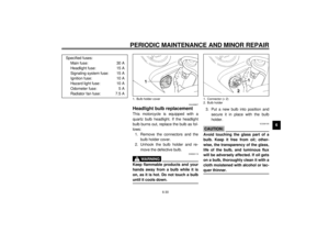
Adjusting spring preload
Turn the adjusting bolt in direction
a to in-
crease spring preload and in direction
b
to decrease spring preload.CI-18E
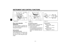
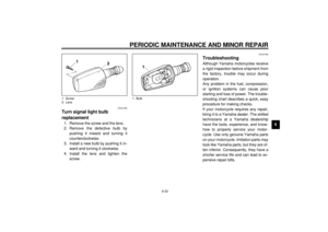
Adjusting damping force
Turn the adjusting screw in direction
a
to increase damping force and in direc-
tion
b to decrease damping force.CI-29E
EC000015CAUTION:@ Never attempt to turn an adjuster
beyond the maximum or minimum
setting. @
1. Spring preload adjusting bolt
2. Adjusting position
3. Standard setting
Soft Standard Hard
Adjusting
position12 3 45
1. Damping force adjusting screwMinimum (soft) 5 clicks out*
Standard 4 clicks out*
Maximum (hard) 0 click out*
* From the fully turned-in position
E_4tx_Functions.fm Page 14 Saturday, October 16, 1999 9:36 AM
Page 29 of 99
INSTRUMENT AND CONTROL FUNCTIONS
3-15
3
EAU01768*
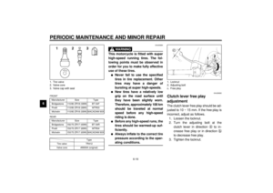
Rear shock absorber
adjustmentThis shock absorber is equipped with
two spring preload adjusters and one
damping force adjuster.
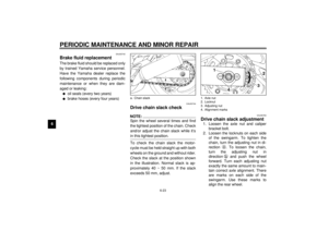
Spring preload
Coarse adjustment (top)Use the special tool in the owner’s tool
kit to turn the lever to “S” when riding
solo and to “H” when riding with a pas-
senger.Fine adjustment (bottom)
Proceed as follows to suit road condi-
tions and the rider’s preference.
1. Loosen the locknut.
2. Turn the adjusting nut in direction
a
to increase spring preload and in di-
rection
b to decrease spring pre-
load.
1. Adjusting lever
1. Locknut
2. Adjusting nut
a. Distance “A”
Spring preload:
Minimum (soft):
Distance “A” = 59 mm
Standard:
Distance “A” = 61 mm
Maximum (hard):
Distance “A” = 63 mm
E_4tx_Functions.fm Page 15 Saturday, October 16, 1999 9:36 AM
Page 30 of 99

INSTRUMENT AND CONTROL FUNCTIONS
3-16
3 3. Tighten the locknut to the speci-
fied torque.
EC000018
CAUTION:@ Always tighten the locknut against
the spring adjusting nut and tighten
the locknut to the specified torque. @
Damping force adjustment
Turn the adjusting knob in direction
a
to increase damping force and in direc-
tion
b to decrease damping force.CI-29E
EC000015CAUTION:@ Never attempt to turn an adjuster
beyond the maximum or minimum
setting. @
EAU00315
WARNING
@ This shock absorber contains high-
ly pressurized nitrogen gas. Read
and understand the following infor-
mation before handling the shock
absorber. The manufacturer cannot
be held responsible for property
damage or personal injury that may
result from improper handling.l
Do not tamper with or attempt to
open the cylinder assembly.
l
Do not subject the shock ab-
sorber to an open flame or other
high heat source. This may
cause the unit to explode due to
excessive gas pressure.
l
Do not deform or damage the
cylinder in any way. Cylinder
damage will result in poor
damping performance.
l
Take your shock absorber to a
Yamaha dealer for any service.
@
Tightening torque:
Locknut:
70 Nm (7.0 m·kg)
1. Adjusting knobMinimum (soft) 20 clicks out*
Standard 10 clicks out*
Maximum (hard) 0 click out*
* From the fully turned-in position
E_4tx_Functions.fm Page 16 Saturday, October 16, 1999 9:36 AM
Page 31 of 99

INSTRUMENT AND CONTROL FUNCTIONS
3-17
3
EAU00324
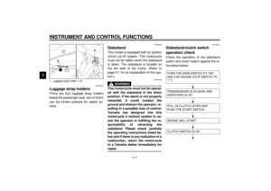
Luggage strap holdersThere are four luggage strap holders
below the passenger seat, two of which
can be turned outward for easier ac-
cess.
EAU00330
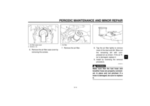
SidestandThis model is equipped with an ignition
circuit cut-off system. The motorcycle
must not be ridden when the sidestand
is down. The sidestand is located on
the left side of the frame. (Refer to
page 5-1 for an explanation of this sys-
tem.)
EW000044
WARNING
@ This motorcycle must not be operat-
ed with the sidestand in the down
position. If the stand is not properly
retracted, it could contact the
ground and distract the operator, re-
sulting in a possible loss of control.
Yamaha has designed into this
motorcycle a lockout system to as-
sist the operator in fulfilling the re-
sponsibility of retracting the
sidestand. Please check carefully
the operating instructions listed be-
low and if there is any indication of a
malfunction, return the motorcycle
to a Yamaha dealer immediately for
repair. @
EAU00331
Sidestand/clutch switch
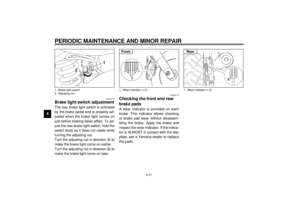
operation checkCheck the operation of the sidestand
switch and clutch switch against the in-
formation below.CD-11E
1. Luggage strap holder (´ 4)
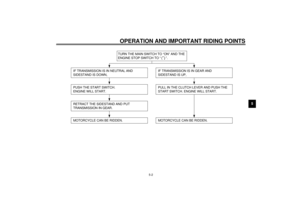
TURN THE MAIN SWITCH TO “ON”
AND THE ENGINE STOP SWITCH TO
“”.TRANSMISSION IS IN GEAR AND
SIDESTAND IS UP.PULL IN CLUTCH LEVER AND
PUSH THE START SWITCH.ENGINE WILL START.CLUTCH SWITCH IS OK.
E_4tx_Functions.fm Page 17 Saturday, October 16, 1999 9:36 AM
Page 32 of 99
INSTRUMENT AND CONTROL FUNCTIONS
3-18
3
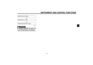
CD-11E
EW000045
WARNING
@ If improper operation is noted, con-
sult a Yamaha dealer immediately. @SIDESTAND IS DOWN.ENGINE WILL STALL.SIDESTAND SWITCH IS OK.
E_4tx_Functions.fm Page 18 Saturday, October 16, 1999 9:36 AM


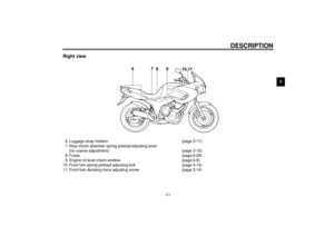


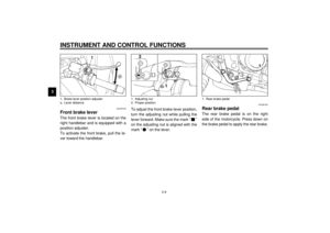


This model is equipped with a fuel tank
breather hose. Before using this motor-
cycle, be sure to:l
Check ho")

