Page 8 of 78

TABLE OF CONTENTS
Throttle cable free play adjustment .................. 6-12
Cam chain adjustment ..................................... 6-12
Valve clearance adjustment ............................. 6-13
Tires ................................................................. 6-13
Wheels ............................................................. 6-15
Clutch lever free play adjustment..................... 6-16
Front brake lever free play adjustment ............ 6-16
Rear brake pedal height and free play
adjustment .................................................... 6-17
Brake light switch adjustment .......................... 6-18
Checking the front brake pads and
rear brake shoes .......................................... 6-19
Inspecting the brake fluid level......................... 6-20
Brake fluid replacement ................................... 6-20
Drive chain slack check ................................... 6-21
Drive chain slack adjustment ........................... 6-22
Drive chain lubrication...................................... 6-23
Cable inspection and lubrication ...................... 6-23
Throttle cable and grip lubrication .................... 6-23
Brake and shift pedal lubrication ...................... 6-24
Brake and clutch lever lubrication .................... 6-24
Center and sidestand lubrication ..................... 6-24
Front fork inspection ........................................ 6-25
Steering inspection .......................................... 6-26
Wheel bearings ................................................ 6-26
Battery.............................................................. 6-26
Fuse replacement ............................................ 6-28
Headlight bulb replacement ............................. 6-29Turn signal and tail/brake light bulb
replacement.................................................. 6-30
Front wheel removal ........................................ 6-30
Front wheel installation .................................... 6-31
Rear wheel removal ......................................... 6-32
Rear wheel installation ..................................... 6-33
Troubleshooting ............................................... 6-33
Troubleshooting chart ...................................... 6-34
MOTORCYCLE CARE AND STORAGE ............. 7-1
Care ................................................................... 7-1
Storage .............................................................. 7-4
SPECIFICATIONS ............................................... 8-1
Specifications ..................................................... 8-1
How to use the conversion table ........................ 8-5
CONSUMER INFORMATION.............................. 9-1
Identification number records............................. 9-1
Key identification number................................... 9-1
Vehicle identification number ............................. 9-1
Model label......................................................... 9-2
789
E_3mw.book Page 2 Monday, February 5, 2001 9:54 AM
Page 32 of 78

PERIODIC MAINTENANCE AND MINOR REPAIR
6-2
6
EAU03686
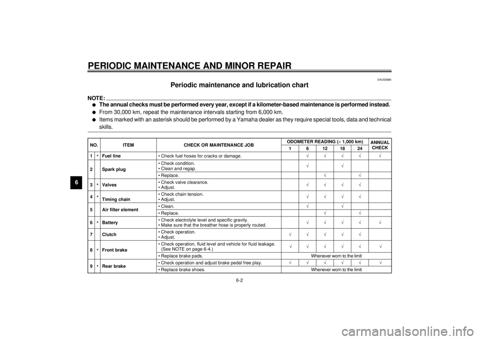
Periodic maintenance and lubrication chart
NOTE:_ l
The annual checks must be performed every year, except if a kilometer-based maintenance is performed instead.
l
From 30,000 km, repeat the maintenance intervals starting from 6,000 km.
l
Items marked with an asterisk should be performed by a Yamaha dealer as they require special tools, data and technical
skills.
_CP-03ENO. ITEM CHECK OR MAINTENANCE JOBODOMETER READING (´1,000 km)
ANNUAL
CHECK
1 6 12 18 24
1
*Fuel line• Check fuel hoses for cracks or damage.ÖÖÖÖ Ö
2 Spark plug• Check condition.
• Clean and regap.ÖÖ
•Replace.ÖÖ
3*Valves• Check valve clearance.
• Adjust.ÖÖÖÖ
4*Timing chain• Check chain tension.
• Adjust.ÖÖÖÖ
5 Air filter element• Clean.ÖÖ
•Replace.ÖÖ
6*Battery• Check electrolyte level and specific gravity.
• Make sure that the breather hose is properly routed.ÖÖÖÖ Ö
7Clutch• Check operation.
• Adjust.ÖÖÖÖÖ
8*Front brake• Check operation, fluid level and vehicle for fluid leakage.
(See NOTE on page 6-4.)ÖÖÖÖÖ Ö
• Replace brake pads. Whenever worn to the limit
9*Rear brake• Check operation and adjust brake pedal free play.ÖÖÖÖÖ Ö
• Replace brake shoes. Whenever worn to the limit
E_3mw.book Page 2 Monday, February 5, 2001 9:54 AM
Page 49 of 78
PERIODIC MAINTENANCE AND MINOR REPAIR
6-19
6
EAU00720
Checking the front brake pads
and rear brake shoes
EAU01119
Front brake
Wear indicator grooves are provided
on each brake pad. These indicators
allow checking of brake pad wear with-
out disassembling the brake. Inspect
the grooves. If they have almost disap-
peared, ask a Yamaha dealer to re-
place the pads.
EAU00727
Rear brake
Apply the brake and inspect the wear
indicator.
If the indicator reaches the wear limit
line, ask a Yamaha dealer to replace
the shoes.
1. Wear indicator groove (´ 2)
2. Brake pads
1. Wear limit
2. Wear indicator
E_3mw.book Page 19 Monday, February 5, 2001 9:54 AM
Page 61 of 78

PERIODIC MAINTENANCE AND MINOR REPAIR
6-31
6 3. Loosen the pinch bolt.
4. Remove the wheel axle. Make
sure the motorcycle is properly
supported.
NOTE:@ Do not depress the brake lever when
the disc and caliper are separated. @
EAU01394
Front wheel installation1. Install the speedometer gear unit
into the wheel hub. Make sure the
wheel hub and the speedometer
gear unit are installed with the pro-
jections meshed into the slots.
2. Lift up the wheel between the front
fork legs and guide the brake disc
between the brake pads. Make
sure the slot in the speedometer
gear unit fits over the stopper on
the front fork outer tube.
3. Install the wheel axle and let the
motorcycle down.4. Push down hard on the handle-
bars several times to check for
proper fork operation.
5. Tighten the wheel axle to the
specified torque.
6. Install the pinch bolt and tighten it
to the specified torque.
7. Install the speedometer cable.
1. Wheel axle
2. Pinch bolt
Tightening torque:
Wheel axle:
59 Nm (5.9 m·kg)
Pinch bolt:
20 Nm (2.0 m·kg)
E_3mw.book Page 31 Monday, February 5, 2001 9:54 AM