2000 YAMAHA SR125 ignition
[x] Cancel search: ignitionPage 13 of 78

3-1
3
EAU00027
3-INSTRUMENT AND CONTROL FUNCTIONS
EAU00029*
Main switch/steering lockThe main switch controls the ignition
and lighting systems. Its operation is
described below.
EAU00036
ON
Electrical circuits are switched on. The
engine can be started. The key cannot
be removed in this position.
EAU00038
OFF
All electrical circuits are switched off.
The key can be removed in this posi-
tion.
EAU00040
LOCK
The steering is locked in this position
and all electrical circuits are switched
off. The key can be removed in this po-
sition.
To lock the steering, turn the handle-
bars all the way to the left. While push-
ing the key into the main switch, turn it
from “OFF” to “LOCK” and remove it.
To release the lock, turn the key to
“OFF” while pushing.
EW000016
WARNING
@ Never turn the key to “OFF” or
“LOCK” when the motorcycle is
moving. The electrical circuits will
be switched off which may result in
loss of control or an accident. Be
sure the motorcycle is stopped be-
fore turning the key to “OFF” or
“LOCK”. @1. Push
2. Turn
E_3mw.book Page 1 Monday, February 5, 2001 9:54 AM
Page 16 of 78

INSTRUMENT AND CONTROL FUNCTIONS
3-4
3
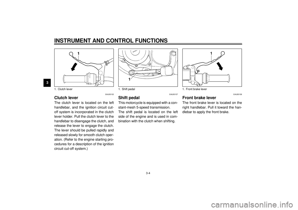
EAU00152
Clutch leverThe clutch lever is located on the left
handlebar, and the ignition circuit cut-
off system is incorporated in the clutch
lever holder. Pull the clutch lever to the
handlebar to disengage the clutch, and
release the lever to engage the clutch.
The lever should be pulled rapidly and
released slowly for smooth clutch oper-
ation. (Refer to the engine starting pro-
cedures for a description of the ignition
circuit cut-off system.)
EAU00157
Shift pedalThis motorcycle is equipped with a con-
stant-mesh 5-speed transmission.
The shift pedal is located on the left
side of the engine and is used in com-
bination with the clutch when shifting.
EAU00158
Front brake leverThe front brake lever is located on the
right handlebar. Pull it toward the han-
dlebar to apply the front brake.
1. Clutch lever
1. Shift pedal
1. Front brake lever
E_3mw.book Page 4 Monday, February 5, 2001 9:54 AM
Page 21 of 78

INSTRUMENT AND CONTROL FUNCTIONS
3-9
3
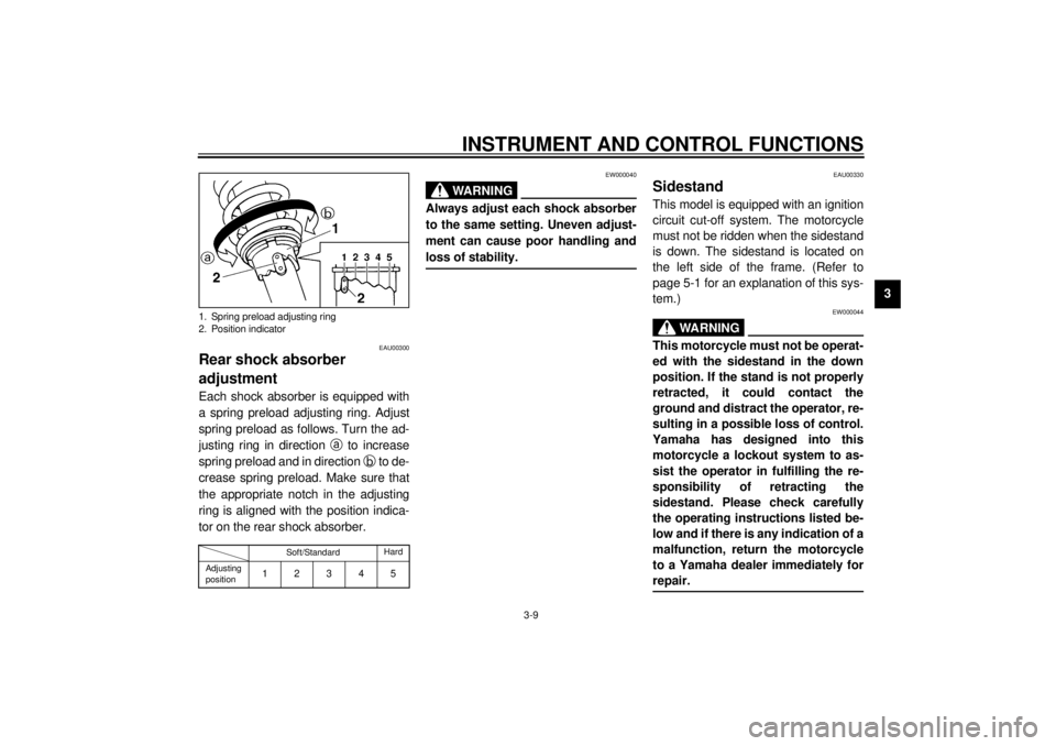
EAU00300
Rear shock absorber
adjustmentEach shock absorber is equipped with
a spring preload adjusting ring. Adjust
spring preload as follows. Turn the ad-
justing ring in direction
a to increase
spring preload and in direction
b to de-
crease spring preload. Make sure that
the appropriate notch in the adjusting
ring is aligned with the position indica-
tor on the rear shock absorber.CI-15EEW000040
WARNING
@ Always adjust each shock absorber
to the same setting. Uneven adjust-
ment can cause poor handling and
loss of stability. @
EAU00330
SidestandThis model is equipped with an ignition
circuit cut-off system. The motorcycle
must not be ridden when the sidestand
is down. The sidestand is located on
the left side of the frame. (Refer to
page 5-1 for an explanation of this sys-
tem.)
EW000044
WARNING
@ This motorcycle must not be operat-
ed with the sidestand in the down
position. If the stand is not properly
retracted, it could contact the
ground and distract the operator, re-
sulting in a possible loss of control.
Yamaha has designed into this
motorcycle a lockout system to as-
sist the operator in fulfilling the re-
sponsibility of retracting the
sidestand. Please check carefully
the operating instructions listed be-
low and if there is any indication of a
malfunction, return the motorcycle
to a Yamaha dealer immediately for
repair. @
1. Spring preload adjusting ring
2. Position indicator
Soft/StandardHard
Adjusting
position
12345
E_3mw.book Page 9 Monday, February 5, 2001 9:54 AM
Page 30 of 78

OPERATION AND IMPORTANT RIDING POINTS
5-6
5
EAU00438
0 ~ 150 km
Avoid operation above 1/3 throttle.
Stop the engine and let it cool for 5 to
10 minutes after every hour of opera-
tion. Vary the speed of the motorcycle
from time to time. Do not operate it at
one set throttle position.
150 ~ 500 km
Avoid prolonged operation above
1/2 throttle.
500 ~ 1,000 km
Avoid cruising speeds in excess of
3/4 throttle.
EC000050
CAUTION:@ After 1,000 km of operation, be sure
to replace the engine oil. @
1,000 km and beyond
Avoid prolonged full-throttle operation.
Vary speed occasionally.
EC000049
CAUTION:@ If any engine trouble should occur
during the break-in period, consult a
Yamaha dealer immediately. @
EAU00457
ParkingWhen parking the motorcycle, stop the
engine and remove the ignition key.
Turn the fuel cock to “OFF” whenever
stopping the engine.
EW000058
WARNING
@ The exhaust system is hot. Park the
motorcycle in a place where pedes-
trians or children are not likely to
touch the motorcycle. Do not park
the motorcycle on a slope or soft
ground; the motorcycle may over-
turn. @
E_3mw.book Page 6 Monday, February 5, 2001 9:54 AM
Page 63 of 78

PERIODIC MAINTENANCE AND MINOR REPAIR
6-33
6
EAU01723*
Rear wheel installation1. Install the rear wheel and the axle.
2. Install the axle nut and let the
motorcycle down.
3. Insert the brake rod into the brake
cam lever and install the brake
pedal free play adjusting nut.
4. Install the brake torque rod bolt
and tighten to the specified tight-
ening torque. Then install a new
cotter pin.
5. Adjust the drive chain free play.
(See page 6-22.)
6. Tighten the axle nut to the speci-
fied tightening torque.7. Adjust the rear brake pedal height
and free play. (See page 6-17.)
EW000103
WARNING
@ Check the operation of the brake
light after adjusting the rear brake. @
EAU01008
TroubleshootingAlthough Yamaha motorcycles receive
a rigid inspection before shipment from
the factory, trouble may occur during
operation.
Any problem in the fuel, compression,
or ignition systems can cause poor
starting and loss of power. The trouble-
shooting chart describes a quick, easy
procedure for making checks.
If your motorcycle requires any repair,
bring it to a Yamaha dealer. The skilled
technicians at a Yamaha dealership
have the tools, experience, and know-
how to properly service your motor-
cycle. Use only genuine Yamaha parts
on your motorcycle. Imitation parts may
look like Yamaha parts, but they are of-
ten inferior. Consequently, they have a
shorter service life and can lead to ex-
pensive repair bills. Specified torque:
Brake torque rod bolt:
25 Nm (2.5 m·kg)
Specified torque:
Axle nut:
65 Nm (6.5 m·kg)
E_3mw.book Page 33 Monday, February 5, 2001 9:54 AM
Page 64 of 78

PERIODIC MAINTENANCE AND MINOR REPAIR
6-34
6
EAU03009
Troubleshooting chart
EW000125
WARNING
@ Never check the fuel system while smoking or in the vicinity of an open flame. @
Check if there is fuel in
the fuel tank.1. Fuel
Enough fuel.
No fuel.
Go to compression check.
Supply fuel.
Engine doesn’t start, go to compression check.
Use the electric starter.2. Compression
There is compression.
No compression.
Go to ignition check.
Ask a Yamaha dealer to
inspect.
Remove spark plug and
check electrodes.3. Ignition
Wet.
Dry.
Wipe clean with dry cloth and correct
spark gap or replace spark plug.
Ask a Yamaha dealer to inspect.
Engine doesn’t start, ask a Yamaha
dealer to inspect.Engine doesn’t start, go to battery
check.Open throttle half-way and start
the engine.
Use the electric starter.4. Battery
Engine turns over
quickly.
Engine turns over
slowly.
Battery good.Check fluid, recharge,
check connections.
E_3mw.book Page 34 Monday, February 5, 2001 9:54 AM
Page 72 of 78

SPECIFICATIONS
8-3
8
Maximum load* 160 kg
Air pressure (cold tire)
Up to 90 kg load*
Front 175 kPa (1.75 kg/cm
2, 1.75 bar)
Rear 200 kPa (2.00 kg/cm2, 2.00 bar)
90 kg load ~ maximum load*
Front 175 kPa (1.75 kg/cm2, 1.75 bar)
Rear 225 kPa (2.25 kg/cm2, 2.25 bar)
*Load is total weight of cargo, rider, passenger and accessories
Wheels
Front
Type Spoke
Size 17 ´ 1.60
Rear
Type Spoke
Size 16 ´ 1.85
Brakes
Front
Type Single disc brake
Operation Right hand operation
Fluid DOT 4 or DOT 3
Rear
Type Drum brake
Operation Right foot operationSuspension
Front
Ty p e Te l e s c o p i c f o r k
Rear
Type Swingarm
Shock absorbers
Front Coil spring / oil damper
Rear Coil spring / oil damper
Wheel travel
Front 120 mm
Rear 76 mm
Electrical system
Ignition system C.D.I.
Charging system
Type C.D.I. magneto
Standard output 14 V, 9 A @ 5,000 r/min
Battery
Type 12N7-3B-1
Voltage, capacity 12 V, 7 AH
Headlight typeQuartz bulb (halogen)
E_3mw.book Page 3 Monday, February 5, 2001 9:54 AM