2000 YAMAHA SR125 ABS
[x] Cancel search: ABSPage 7 of 78

EAU00009
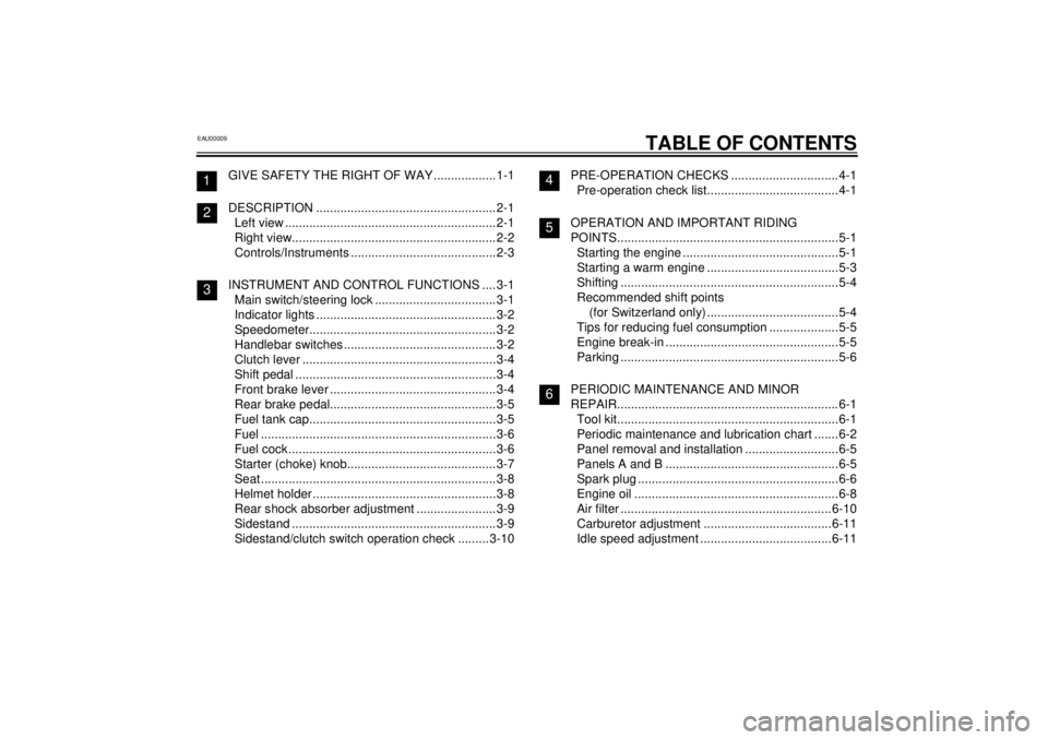
TABLE OF CONTENTS
GIVE SAFETY THE RIGHT OF WAY ..................1-1
DESCRIPTION ....................................................2-1
Left view ............................................................. 2-1
Right view...........................................................2-2
Controls/Instruments ..........................................2-3
INSTRUMENT AND CONTROL FUNCTIONS ....3-1
Main switch/steering lock ................................... 3-1
Indicator lights ....................................................3-2
Speedometer......................................................3-2
Handlebar switches ............................................3-2
Clutch lever ........................................................3-4
Shift pedal ..........................................................3-4
Front brake lever ................................................ 3-4
Rear brake pedal................................................ 3-5
Fuel tank cap......................................................3-5
Fuel ....................................................................3-6
Fuel cock ............................................................3-6
Starter (choke) knob...........................................3-7
Seat ....................................................................3-8
Helmet holder .....................................................3-8
Rear shock absorber adjustment .......................3-9
Sidestand ...........................................................3-9
Sidestand/clutch switch operation check ......... 3-10PRE-OPERATION CHECKS ...............................4-1
Pre-operation check list......................................4-1
OPERATION AND IMPORTANT RIDING
POINTS................................................................5-1
Starting the engine .............................................5-1
Starting a warm engine ......................................5-3
Shifting ...............................................................5-4
Recommended shift points
(for Switzerland only) ......................................5-4
Tips for reducing fuel consumption ....................5-5
Engine break-in ..................................................5-5
Parking ...............................................................5-6
PERIODIC MAINTENANCE AND MINOR
REPAIR................................................................6-1
Tool kit................................................................6-1
Periodic maintenance and lubrication chart .......6-2
Panel removal and installation ...........................6-5
Panels A and B ..................................................6-5
Spark plug ..........................................................6-6
Engine oil ...........................................................6-8
Air filter .............................................................6-10
Carburetor adjustment .....................................6-11
Idle speed adjustment ......................................6-11
123
456
E_3mw.book Page 1 Monday, February 5, 2001 9:54 AM
Page 11 of 78

DESCRIPTION
2-2
2
Right view8. Seat (page 3-8)
9. Rear shock absorber spring
preload adjusting ring (page 3-9)
10. Tool kit (page 6-1)
11. Air filter (page 6-10)12. Engine oil filler cap
13. Rear brake pedal (page 3-5)
14. Footrest
15. Battery (page 6-26)
E_3mw.book Page 2 Monday, February 5, 2001 9:54 AM
Page 21 of 78

INSTRUMENT AND CONTROL FUNCTIONS
3-9
3
EAU00300
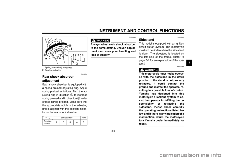
Rear shock absorber
adjustmentEach shock absorber is equipped with
a spring preload adjusting ring. Adjust
spring preload as follows. Turn the ad-
justing ring in direction
a to increase
spring preload and in direction
b to de-
crease spring preload. Make sure that
the appropriate notch in the adjusting
ring is aligned with the position indica-
tor on the rear shock absorber.CI-15EEW000040
WARNING
@ Always adjust each shock absorber
to the same setting. Uneven adjust-
ment can cause poor handling and
loss of stability. @
EAU00330
SidestandThis model is equipped with an ignition
circuit cut-off system. The motorcycle
must not be ridden when the sidestand
is down. The sidestand is located on
the left side of the frame. (Refer to
page 5-1 for an explanation of this sys-
tem.)
EW000044
WARNING
@ This motorcycle must not be operat-
ed with the sidestand in the down
position. If the stand is not properly
retracted, it could contact the
ground and distract the operator, re-
sulting in a possible loss of control.
Yamaha has designed into this
motorcycle a lockout system to as-
sist the operator in fulfilling the re-
sponsibility of retracting the
sidestand. Please check carefully
the operating instructions listed be-
low and if there is any indication of a
malfunction, return the motorcycle
to a Yamaha dealer immediately for
repair. @
1. Spring preload adjusting ring
2. Position indicator
Soft/StandardHard
Adjusting
position
12345
E_3mw.book Page 9 Monday, February 5, 2001 9:54 AM
Page 33 of 78

PERIODIC MAINTENANCE AND MINOR REPAIR
6-3
6
10
*Wheels• Check runout, spoke tightness and for damage.
• Tighten spokes if necessary.ÖÖÖÖ
11*Tires• Check tread depth and for damage.
• Replace if necessary.
• Check air pressure.
• Correct if necessary.ÖÖÖÖ
12*Wheel bearings• Check bearing for looseness or damage.ÖÖÖÖ
13*Swingarm• Check operation and for excessive play.ÖÖÖÖ
14 Drive chain• Check chain slack.
• Make sure that the rear wheel is properly aligned.
• Clean and lubricate.Every 1,000 km and after washing
the motorcycle or riding in the rain.
15*Steering bearings• Check bearing play and steering for roughness.ÖÖÖÖÖ
• Lubricate with lithium-soap-based grease. Every 24,000 km
16*Chassis fasteners• Make sure that all nuts, bolts and screws are properly tightened.ÖÖÖÖ Ö
17 Sidestand, centerstand• Check operation.
• Lubricate.ÖÖÖÖ Ö
18*Sidestand switch• Check operation.ÖÖÖÖÖ Ö
19*Front fork• Check operation and for oil leakage.ÖÖÖÖ
20*Shock absorber
assemblies• Check operation and shock absorbers for oil leakage.ÖÖÖÖ
21*Carburetor• Check starter (choke) operation.
• Adjust engine idling speed.ÖÖÖÖÖ Ö
22 Engine oil• Change.ÖÖÖÖÖ Ö
23 Engine oil filter element•Clean.ÖÖÖ
24*Front and rear brake
switches• Check operation.ÖÖÖÖÖ Ö
25 Moving parts and cables• Lubricate.ÖÖÖÖ Ö NO. ITEM CHECK OR MAINTENANCE JOBODOMETER READING (´1,000 km)
ANNUAL
CHECK
1 6 12 18 24
E_3mw.book Page 3 Monday, February 5, 2001 9:54 AM
Page 45 of 78

PERIODIC MAINTENANCE AND MINOR REPAIR
6-15
6
EAU00681
WARNING
@ l
Operating the motorcycle with
excessively worn tires decrease
riding stability and can lead to
loss of control. Have excessive-
ly worn tires replaced by a
Yamaha dealer immediately.
Brakes, tires, and related wheel
parts replacement should be
left to a Yamaha Service Techni-
cian.
l
Patching a punctured tube is
not recommended. If it is abso-
lutely necessary to do so, use
great care and replace the tube
as soon as possible with a good
quality replacement.
@
EAU00685
WheelsTo ensure maximum performance,
long service, and safe operation, note
the following:l
Always inspect the wheels before
a ride. Check for cracks, bends or
warpage of the wheel. Be sure the
spokes are tight and undamaged.
If any abnormal condition exists in
a wheel, consult a Yamaha dealer.
Do not attempt even small repairs
to the wheel. If a wheel is de-
formed or cracked, it must be re-
placed.
l
Tires and wheels should be bal-
anced whenever either one is
changed or replaced. Failure to
have a wheel balanced can result
in poor performance, adverse han-
dling characteristics, and short-
ened tire life.
l
Ride at moderate speeds after
changing a tire since the tire sur-
face must first be broken in for it to
develop its optimal characteristics.
E_3mw.book Page 15 Monday, February 5, 2001 9:54 AM
Page 67 of 78

MOTORCYCLE CARE AND STORAGE
7-3
7 After riding in the rain, near the sea or
on salt-sprayed roadsSince sea salt or salt sprayed on the
roads in the winter are extremely corro-
sive in combination with water, carry
out the following steps after each ride
in the rain, near the sea or on salt-
sprayed roads. (Salt sprayed in the
winter may remain on the roads well
into spring.)
1. Clean your motorcycle with cold
water and soap after the engine
has cooled down.
ECA00012
CAUTION:@ Do not use warm water since it in-
creases the corrosive action of the
salt. @2. Be sure to apply a corrosion pro-
tection spray on all (even chrome-
and nickel-plated) metal surfaces
to prevent corrosion.After cleaning
1. Dry the motorcycle with a chamois
or an absorbing cloth.
2. Immediately dry the drive chain
and lubricate it to prevent it from
rusting.
3. Use a chrome polish to shine
chrome, aluminum and stainless-
steel parts, including the exhaust
system. (Even the thermally in-
duced discoloring of stainless-
steel exhaust systems can be re-
moved through polishing.)
4. To prevent corrosion, it is recom-
mended to apply a corrosion pro-
tection spray on all (even chrome-
and nickel-plated) metal surfaces.
5. Use spray oil as a universal clean-
er to remove any remaining dirt.
6. Touch up minor paint damage
caused by stones, etc.
7. Wax all painted surfaces.
8. Let the motorcycle dry completely
before storing it or covering it.
EWA00001
WARNING
@ Make sure that there is no oil or wax
on the brakes and tires. If neces-
sary, clean the brake discs and lin-
ings with a regular brake disc
cleaner or acetone, and wash the
tires with warm water and mild soap.
Then, carefully test the motorcycle
for its braking performance and cor-
nering behavior. @
E_3mw.book Page 3 Monday, February 5, 2001 9:54 AM
Page 72 of 78

SPECIFICATIONS
8-3
8
Maximum load* 160 kg
Air pressure (cold tire)
Up to 90 kg load*
Front 175 kPa (1.75 kg/cm
2, 1.75 bar)
Rear 200 kPa (2.00 kg/cm2, 2.00 bar)
90 kg load ~ maximum load*
Front 175 kPa (1.75 kg/cm2, 1.75 bar)
Rear 225 kPa (2.25 kg/cm2, 2.25 bar)
*Load is total weight of cargo, rider, passenger and accessories
Wheels
Front
Type Spoke
Size 17 ´ 1.60
Rear
Type Spoke
Size 16 ´ 1.85
Brakes
Front
Type Single disc brake
Operation Right hand operation
Fluid DOT 4 or DOT 3
Rear
Type Drum brake
Operation Right foot operationSuspension
Front
Ty p e Te l e s c o p i c f o r k
Rear
Type Swingarm
Shock absorbers
Front Coil spring / oil damper
Rear Coil spring / oil damper
Wheel travel
Front 120 mm
Rear 76 mm
Electrical system
Ignition system C.D.I.
Charging system
Type C.D.I. magneto
Standard output 14 V, 9 A @ 5,000 r/min
Battery
Type 12N7-3B-1
Voltage, capacity 12 V, 7 AH
Headlight typeQuartz bulb (halogen)
E_3mw.book Page 3 Monday, February 5, 2001 9:54 AM