Page 3175 of 4770

DTC B0138/72 DLC1
± DIAGNOSTICSSUPPLEMENTAL RESTRAINT SYSTEM
DI±755
990 Author�: Date�:
4 Check P/T squi")
AB0118
R13006AB0119H01018
H01085H01222
"u
E1TcACC ON
or Airbag
Sensor
Assembly P/T Squib (LH)
DTC B0138/72 DLC1
± DIAGNOSTICSSUPPLEMENTAL RESTRAINT SYSTEM
DI±755
990 Author�: Date�:
4 Check P/T squib (LH).
PREPARATION:
(a) Turn ignition switch to LOCK.
(b) Disconnect negative (±) terminal cable from the battery,
and wait at least for 90 seconds.
(c) Connect the seat belt pretensioner (LH) connector.
(d) Connect negative (±) terminal cable to the battery, and
wait at least for 2 seconds.
CHECK:
(a) Turn ignition switch to ACC or ON, and wait at least for 20
seconds.
(b) Clear DTC stored in memory.
(See step 5 on page DI±626)
(c) Turn ignition switch to LOCK, and wait at least for 20 se-
conds.
(d) Turn ignition switch to ACC or ON, and wait at least for 20
seconds.
(e) Check DTC.
(See page DI±626)
OK:
DTC B0138/72 is not output.
HINT:
Codes other than code B0138/72 may be output at this time, but
they are not relevant to this check.
NG Replace seat belt pretensioner (LH).
OK
From the results of the above inspection, the malfunctioning part can now be considered normal.
To make sure of this, use the simulation method to check. If the malfunctioning part can not be
detected by the simulation method, replace all SRS components including the wire harness.
Page 3176 of 4770
 (+)ONAirbag Sensor Assembly
ACC
IG2
DI±756
± DIAGNOSTICSSUPPLEMENTAL RESTRAINT SYSTEM
991 Author�: Date�:
DTC B1100/31 Airbag Sensor Assembly Malfunction
CIRCUIT DESCRIPTION")
AB0119H01298H01299
(±) (+)ONAirbag Sensor Assembly
ACC
IG2
DI±756
± DIAGNOSTICSSUPPLEMENTAL RESTRAINT SYSTEM
991 Author�: Date�:
DTC B1100/31 Airbag Sensor Assembly Malfunction
CIRCUIT DESCRIPTION
The airbag sensor assembly consists of a airbag sensor, safing sensor, drive circuit, diagnosis circuit and
ignition control, etc.
It receives signals from the airbag sensor, judges whether or not the SRS must be activated, and detects
diagnosis system malfunction.
DTC B1100/31 is recorded when occurrence of a malfunction in the airbag sensor assembly is detected.
DTC No.DTC Detecting ConditionTrouble Area
B1100/31�Airbag sensor assembly malfunction�Airbag sensor assembly
INSPECTION PROCEDURE
HINT:
When a malfunction code other than code B1100/31 is displayed at the same time, first repair the malfunction
indicated by the malfunction code other than code B1100/31.
1 Prepare for inspection. (See step 1 on page DI±787)
2 Check voltage at IG2 and ACC of airbag sensor assembly.
CHECK:
(a) Turn ignition switch to ON.
(b) Measure the voltage between body ground and terminals
each of IG2 and ACC of the airbag sensor assembly con-
nector.
OK:
Voltage: 10 ± 14 V
NG Check that an abnormality occurs on the battery
and charging system.
OK
DI1BM±18
Page 3177 of 4770
AB0118
R13006AB0119
FI1394
H00022
ACCON
or
DLC1
E1
TcDTC B1100/31
± DIAGNOSTICSSUPPLEMENTAL RESTRAINT SYSTEM
DI±757
992 Author�: Date�:
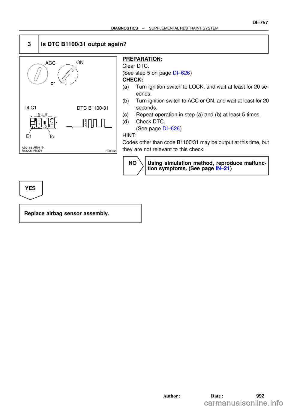
3 Is DTC B1100/31 output again?
PREPARATION:
Clear DTC.
(See step 5 on page DI±626)
CHECK:
(a) Turn ignition switch to LOCK, and wait at least for 20 se-
conds.
(b) Turn ignition switch to ACC or ON, and wait at least for 20
seconds.
(c) Repeat operation in step (a) and (b) at least 5 times.
(d) Check DTC.
(See page DI±626)
HINT:
Codes other than code B1100/31 may be output at this time, but
they are not relevant to this check.
NO Using simulation method, reproduce malfunc-
tion symptoms. (See page IN±21)
YES
Replace airbag sensor assembly.
Page 3178 of 4770
H01450
Side Aribag Sensor Assembly (RH)
Airbag Sensor Assembly
GR
LG
L±Y
P ESR
FSR
SSR+
VUPR4
3
2
1C197
9
10
12ESR
FSR
SSR+
VUPR C19
C19
C19 DI±758
± DIAGNOSTICSSUPPLEMENTAL RESTRAINT SYSTEM
993 Author�: Date�:
DTC B1140/32 Side Airbag Sensor Assembly (RH)
Malfunction
CIRCUIT DESCRIPTION
The side airbag sensor assembly (RH) consists of the safing sensor, diagnosis circuit and lateral decelera-
tion sensor, etc.
It receives signals from the lateral deceleration sensor, judges whether or not the SRS must be activated,
and diagnosis system malfunction.
DTC B1140/32 is recorded when occurrence of a malfunction in the side airbag sensor assembly (RH) is
detected.
DTC No.DTC Detecting ConditionTrouble Area
B1140/32�Side airbag sensor assembly (RH) malfunction
�Side airbag sensor assembly (RH)
�Wire harness
�Airbag sensor assembly
WIRING DIAGRAM
DI4L8±01
Page 3179 of 4770
R13006H09528AB0118AB0119H09527
ACC
ON
or
DLC1
E1
TcDTC B1140/32
± DIAGNOSTICSSUPPLEMENTAL RESTRAINT SYSTEM
DI±759
994 Author�: Date�:
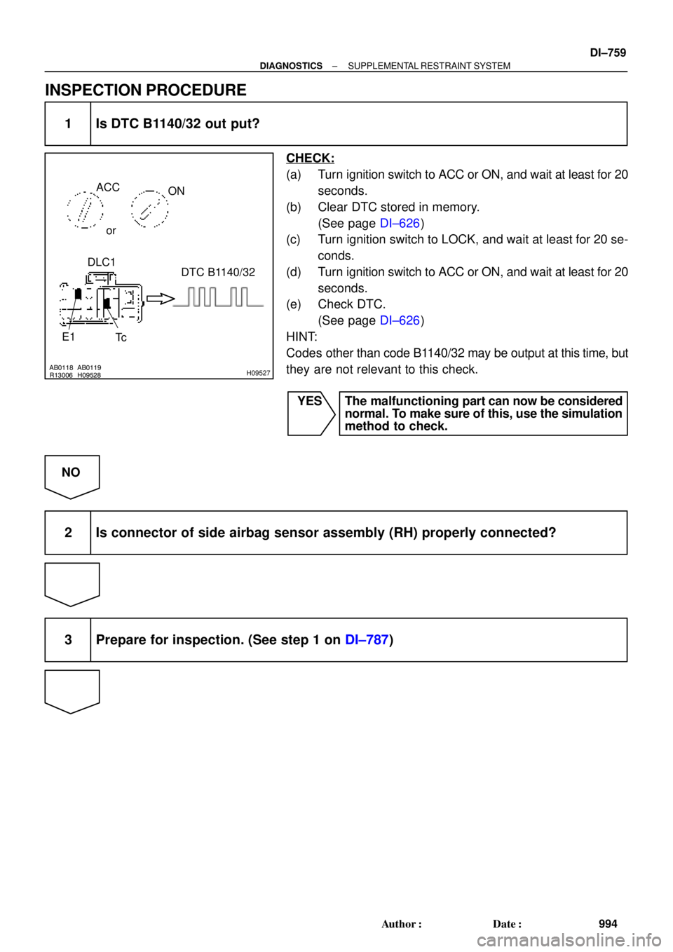
INSPECTION PROCEDURE
1 Is DTC B1140/32 out put?
CHECK:
(a) Turn ignition switch to ACC or ON, and wait at least for 20
seconds.
(b) Clear DTC stored in memory.
(See page DI±626)
(c) Turn ignition switch to LOCK, and wait at least for 20 se-
conds.
(d) Turn ignition switch to ACC or ON, and wait at least for 20
seconds.
(e) Check DTC.
(See page DI±626)
HINT:
Codes other than code B1140/32 may be output at this time, but
they are not relevant to this check.
YES The malfunctioning part can now be considered
normal. To make sure of this, use the simulation
method to check.
NO
2 Is connector of side airbag sensor assembly (RH) properly connected?
3 Prepare for inspection. (See step 1 on DI±787)
Page 3180 of 4770
H01015H01058 H01036H01160
Airbag
Sensor
Assembly
(±)(+) Side Airbag Sensor
Assembly (RH)
SSR+ Airbag Sensor
Assembly
ESR SSR+
ESRu "
DI±760
± DIAGNOSTICSSUPPLEMENTAL RESTRAINT SYSTEM
995 Author�: Date�:
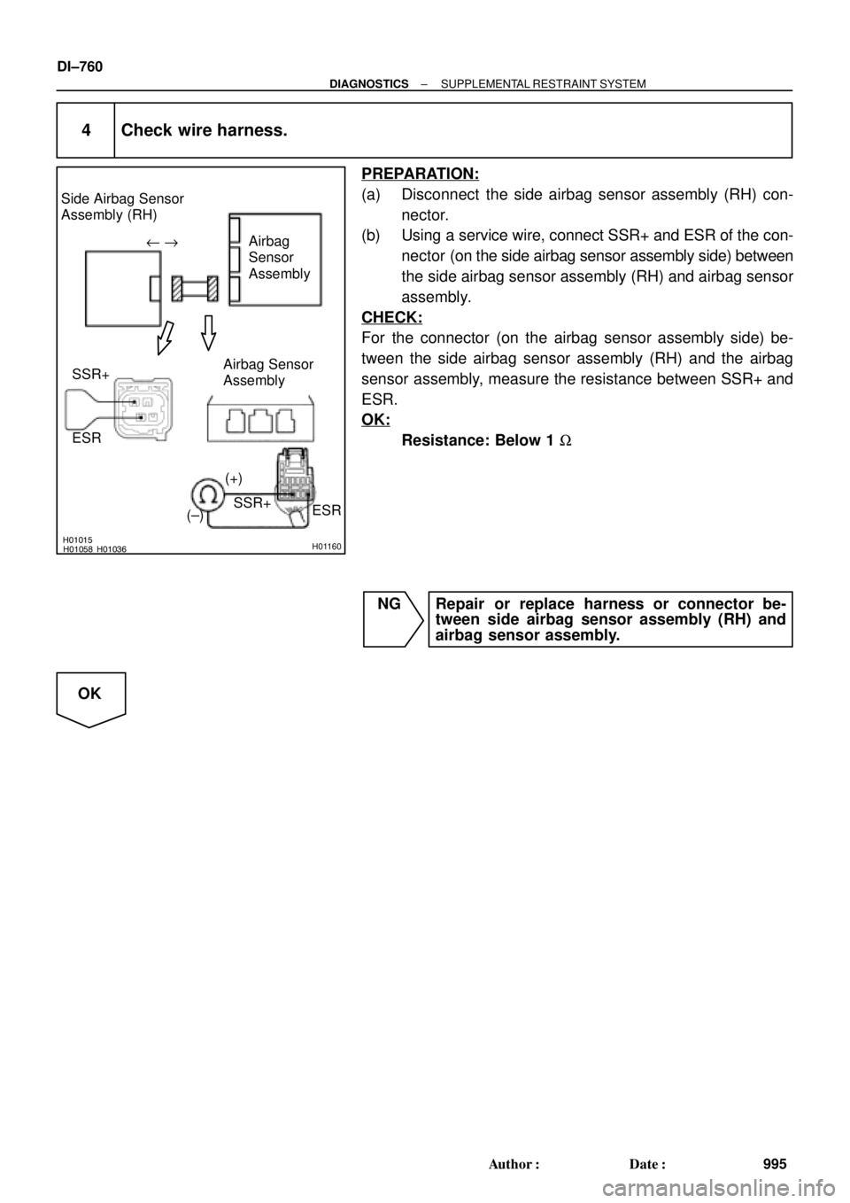
4 Check wire harness.
PREPARATION:
(a) Disconnect the side airbag sensor assembly (RH) con-
nector.
(b) Using a service wire, connect SSR+ and ESR of the con-
nector (on the side airbag sensor assembly side) between
the side airbag sensor assembly (RH) and airbag sensor
assembly.
CHECK:
For the connector (on the airbag sensor assembly side) be-
tween the side airbag sensor assembly (RH) and the airbag
sensor assembly, measure the resistance between SSR+ and
ESR.
OK:
Resistance: Below 1 W
NG Repair or replace harness or connector be-
tween side airbag sensor assembly (RH) and
airbag sensor assembly.
OK
Page 3181 of 4770
H01015H01059H01037H01161
Airbag
Sensor
Assembly
(±)(+) Side Airbag Sensor
Assembly (RH)
VUPRAirbag Sensor
Assembly
FSR
VUPR
FSR
± DIAGNOSTICSSUPPLEMENTAL RESTRAINT SYSTEM
DI±761
996 Author�: Date�:
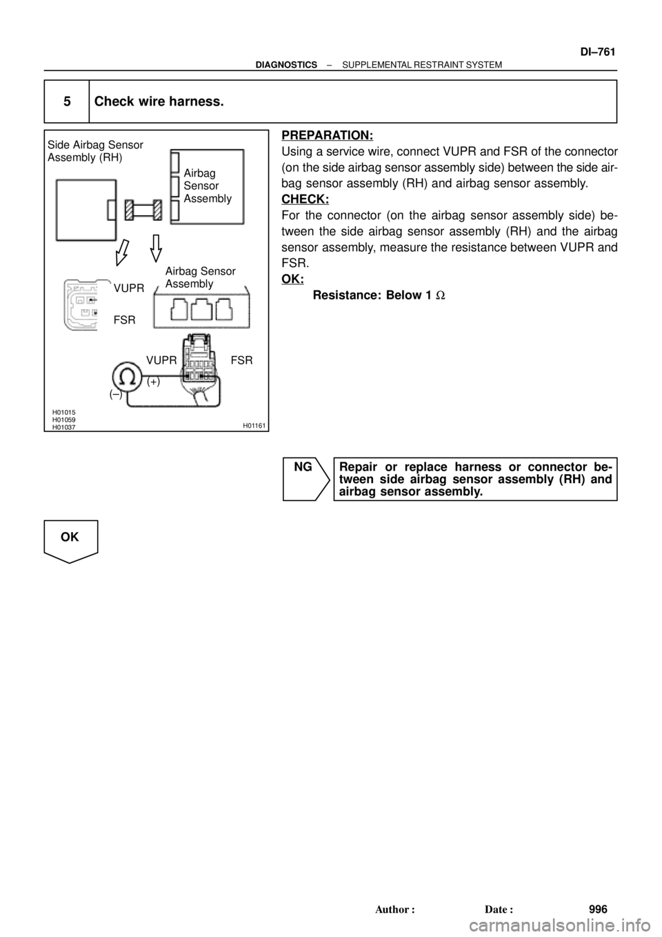
5 Check wire harness.
PREPARATION:
Using a service wire, connect VUPR and FSR of the connector
(on the side airbag sensor assembly side) between the side air-
bag sensor assembly (RH) and airbag sensor assembly.
CHECK:
For the connector (on the airbag sensor assembly side) be-
tween the side airbag sensor assembly (RH) and the airbag
sensor assembly, measure the resistance between VUPR and
FSR.
OK:
Resistance: Below 1 W
NG Repair or replace harness or connector be-
tween side airbag sensor assembly (RH) and
airbag sensor assembly.
OK
Page 3182 of 4770

Airbag
Sensor
Assembly
Airbag Sensor Assembly
SSR+ (+)VUPR
FSR
(±)
AB0119
H01013
H01039
H08270
Side Airbag Sensor
Assembly (RH)
Airbag
Sensor
Assem")
H01013H01038H01162
Side Airbag Sensor
Assembly (RH)
Airbag
Sensor
Assembly
Airbag Sensor Assembly
SSR+ (+)VUPR
FSR
(±)
AB0119
H01013
H01039
H08270
Side Airbag Sensor
Assembly (RH)
Airbag
Sensor
Assembly
Airbag Sensor Assembly
SSR+
(+)VUPRFSR
(±)
ESR
ON
DI±762
± DIAGNOSTICSSUPPLEMENTAL RESTRAINT SYSTEM
997 Author�: Date�:
6 Check wire harness (to ground).
CHECK:
For the connector (on the airbag sensor assembly side) be-
tween the side airbag sensor assembly (RH) and the airbag
sensor assembly, measure the resistance between body
ground and each of SSR+, VUPR and FSR.
OK:
Resistance: Below 1 W
NG Repair or replace harness or connector be-
tween side airbag sensor assembly (RH) and
airbag sensor assembly.
OK
7 Check wire harness (to B+).
CHECK:
(a) Turn ignition switch to ON.
(b) For the connector (on the airbag sensor assembly side)
between the side airbag sensor assembly (RH) and the
airbag sensor assembly, measure the voltage between
the body ground and each of SSR+, VUPR, ESR and
FSR.
OK:
Voltage: 0 V
NG Repair or replace harness or connector be-
tween side airbag sensor assembly (RH) and
airbag sensor assembly.
OK

Airbag Sensor Assembly
GR
LG
L±Y
P ESR
FSR
SSR+
VUPR4
3
2
1C197
9
10
12ESR
FSR
SSR+
VUPR C19
C19
C19 DI±758
± DIAGNOSTICSSUPPLEMENTAL RESTRAINT SYSTEM
993 Au")