Page 3087 of 4770
 (+)P+ ON
± DIAGNOSTICSSUPPLEMENTAL RESTRAINT SYSTEM
DI±667
902 Author�: Date�:
DTC B0108/52 Short in P Squib Circuit (to B+)
CIRCUIT DES")
H01022H02146
AB0119
H08262
P SquibAirbag
Sensor
Assembly
(±) (+)P+ ON
± DIAGNOSTICSSUPPLEMENTAL RESTRAINT SYSTEM
DI±667
902 Author�: Date�:
DTC B0108/52 Short in P Squib Circuit (to B+)
CIRCUIT DESCRIPTION
The P squib circuit consists of the airbag sensor assembly and front passenger airbag assembly.
It causes the SRS to deploy when the SRS deployment conditions are satisfied.
For details of the function of each component, see OPERATION on page RS±2.
DTC B0108/52 is recorded when a B+ short is detected in the P squib circuit.
DTC No.DTC Detecting ConditionTrouble Area
B0108/52
�Short circuit in P squib wire harness (to B+)
�P squib malfunction
�Airbag sensor assembly malfunction�Front passenger airbag assembly (P squib)
�Airbag sensor assembly
�Wire harness
WIRING DIAGRAM
See page DI±657.
INSPECTION PROCEDURE
1 Prepare for inspection. (See step 1 on page DI±787)
2 Check P squib circuit.
CHECK:
(a) Turn ignition switch to ON.
(b) For the connector (on the front passenger airbag assem-
bly side) between the front passenger airbag assembly
and the airbag sensor assembly, measure the voltage be-
tween the P+ and body ground.
OK:
Voltage: 0 V
NG Repair or replace harness or connector be-
tween front passenger airbag assembly and air-
bag sensor assembly.
OK
DI1B9±16
Page 3088 of 4770

AB0118
R13006AB0118H01023
H01076 H02144H02257
P Squib
Airbag
Sensor
Assembly
P+
P±ACC
or
DTC B0108/52
DLC1
ON " u
E1
Tc
DI±668
± DIAGNOSTICSSUPPLEMENTAL RESTRAINT SYSTEM
903 Author�: Date�:
3 Check airbag sensor assembly.
PREPARATION:
(a) Connect the connector to the airbag sensor assembly.
(b) Using a service wire, connect P+ and P± of the connector
(on the front passenger airbag assembly side) between
the front passenger airbag assembly and the airbag sen-
sor assembly.
(c) Connect negative (±) terminal cable to the battery, and
wait at least for 2 seconds.
CHECK:
(a) Turn ignition switch to ACC or ON and wait at least for 20
seconds.
(b) Clear DTC stored in memory.
(See step 5 on page DI±626)
(c) Turn ignition switch to LOCK, and wait at least for 20 se-
conds.
(d) Turn ignition switch to ACC or ON, and wait at least for 20
seconds.
(e) Check DTC.
(See page DI±626)
OK:
DTC B0108/52 is not output.
HINT:
Codes other than code B0108/52 may be output at this time, but
they are not relevant to this check.
NG Replace airbag sensor assembly.
OK
Page 3089 of 4770

AB0118
R13006AB0119H01024
H01076H01199
"u
E1Tc ACC ON
or
DTC B0108/52 DLC1Airbag
Sensor
Assembly P Squib
± DIAGNOSTICSSUPPLEMENTAL RESTRAINT SYSTEM
DI±669
904 Author�: Date�:
4 Check P squib.
PREPARATION:
(a) Turn ignition switch to LOCK.
(b) Disconnect negative (±) terminal cable from the battery,
and wait at least for 90 seconds.
(c) Connect the front passenger airbag assembly connector.
(d) Connect negative (±) terminal cable to the battery, and
wait at least for 2 seconds.
CHECK:
(a) Turn ignition switch to ACC or ON, and wait at least for 20
seconds.
(b) Clear DTC stored in memory.
(See page DI±626)
(c) Turn ignition switch to LOCK, and wait at least for 20 se-
conds.
(d) Turn ignition switch to ACC or ON, and wait at least for 20
seconds.
(e) Check DTC.
(See page DI±626)
OK:
DTC B0108/52 is not output.
HINT:
Codes other than code B0108/52 may be output at this time, but
they are not relevant to this check.
NG Replace front passenger airbag assembly.
OK
From the results of the above inspection, the malfunctioning part can now be considered normal.
To make sure of this, use the simulation method to check. If the malfunctioning part can not be
detected by the simulation method, replace all SRS components including the wire harness.
Page 3090 of 4770
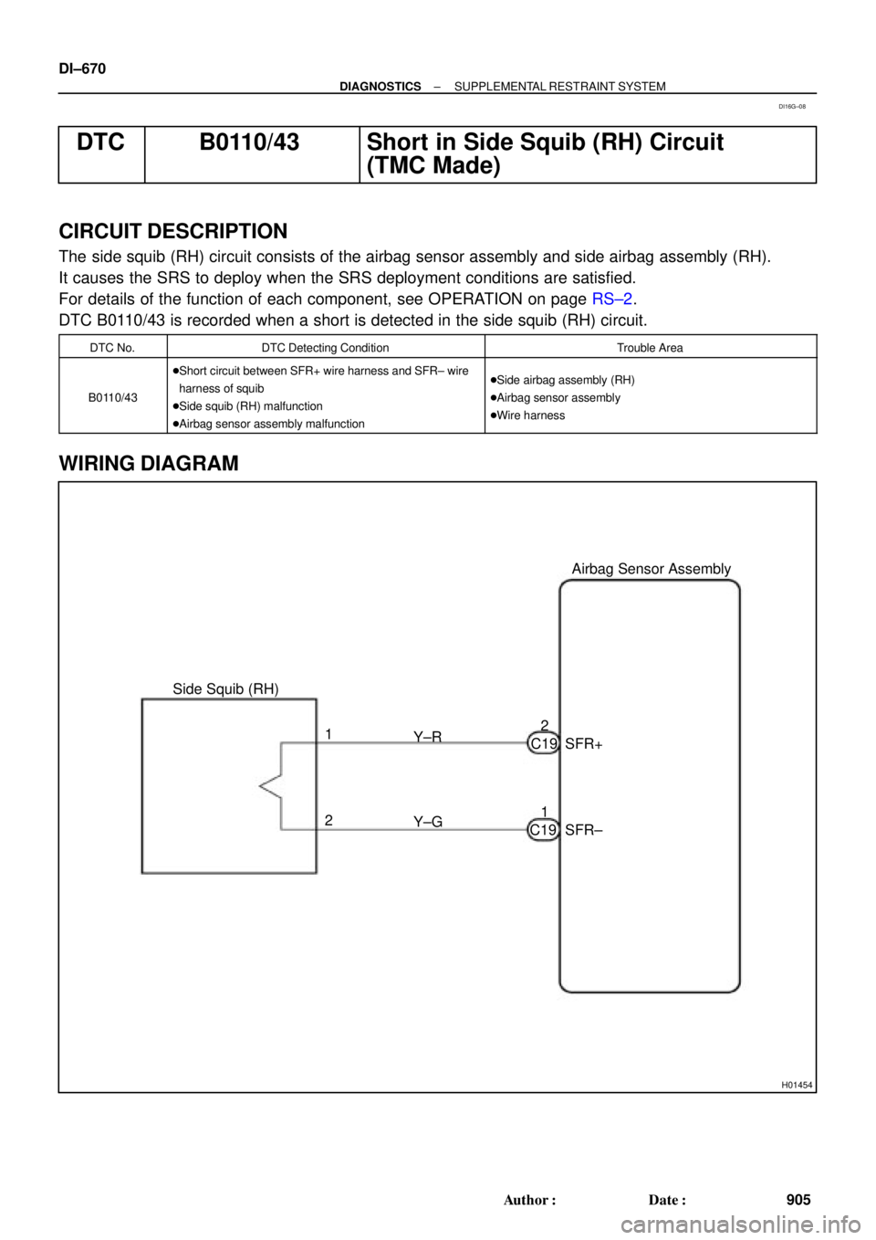
H01454
Side Squib (RH)Airbag Sensor Assembly
SFR+
SFR± Y±R
Y±G 1
21 2
C19
C19 DI±670
± DIAGNOSTICSSUPPLEMENTAL RESTRAINT SYSTEM
905 Author�: Date�:
DTC B0110/43 Short in Side Squib (RH) Circuit
(TMC Made)
CIRCUIT DESCRIPTION
The side squib (RH) circuit consists of the airbag sensor assembly and side airbag assembly (RH).
It causes the SRS to deploy when the SRS deployment conditions are satisfied.
For details of the function of each component, see OPERATION on page RS±2.
DTC B0110/43 is recorded when a short is detected in the side squib (RH) circuit.
DTC No.DTC Detecting ConditionTrouble Area
B0110/43
�Short circuit between SFR+ wire harness and SFR± wire
harness of squib
�Side squib (RH) malfunction
�Airbag sensor assembly malfunction�Side airbag assembly (RH)
�Airbag sensor assembly
�Wire harness
WIRING DIAGRAM
DI16G±08
Page 3091 of 4770
H01019W03859H01180
Squib (RH)Airbag
Sensor
Assembly
SFR+
(±) (+)SFR±
± DIAGNOSTICSSUPPLEMENTAL RESTRAINT SYSTEM
DI±671
906 Author�: Date�:
INSPECTION PROCEDURE
1 Prepare for inspection. (See step 1 on page DI±787)
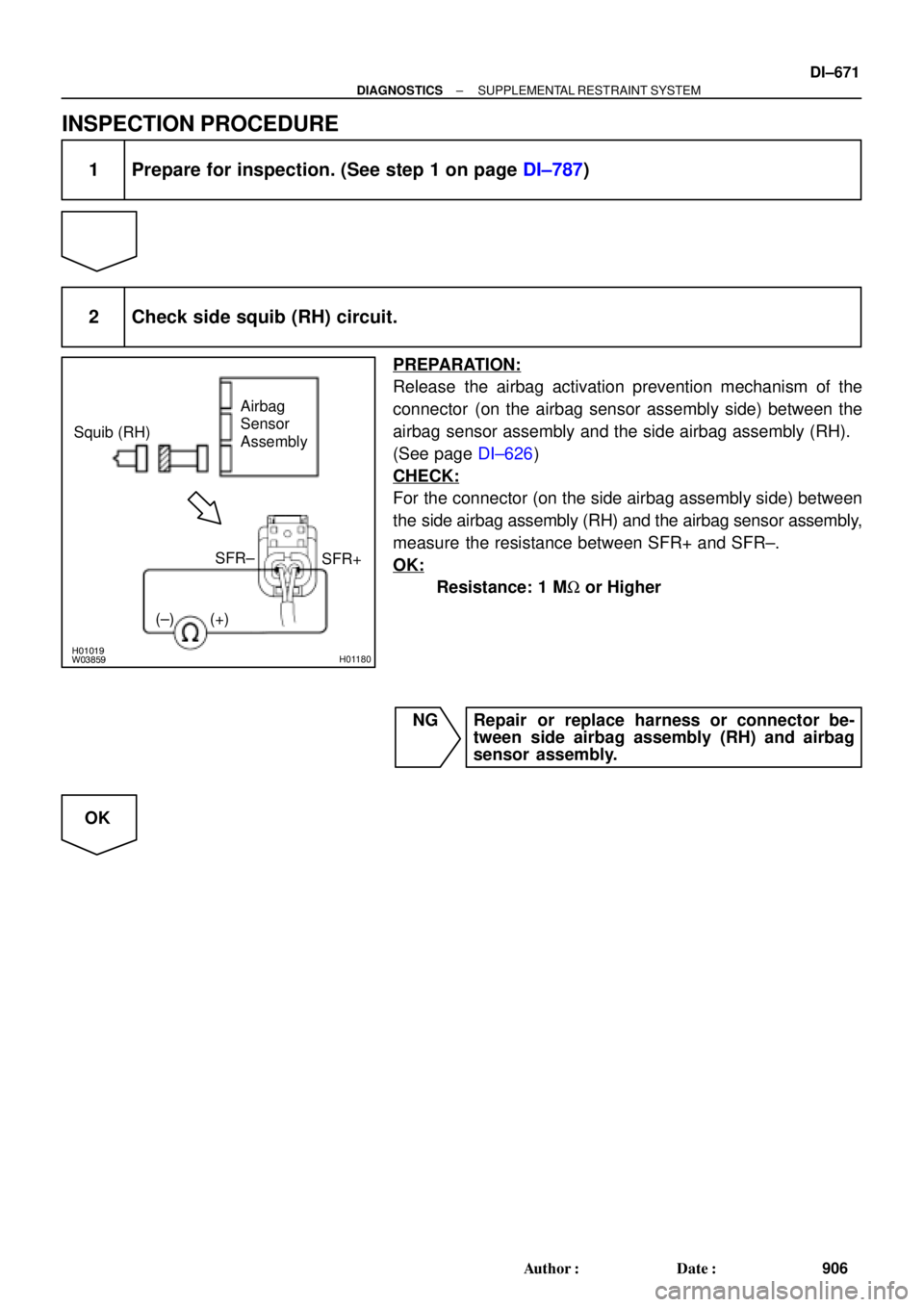
2 Check side squib (RH) circuit.
PREPARATION:
Release the airbag activation prevention mechanism of the
connector (on the airbag sensor assembly side) between the
airbag sensor assembly and the side airbag assembly (RH).
(See page DI±626)
CHECK:
For the connector (on the side airbag assembly side) between
the side airbag assembly (RH) and the airbag sensor assembly,
measure the resistance between SFR+ and SFR±.
OK:
Resistance: 1 MW or Higher
NG Repair or replace harness or connector be-
tween side airbag assembly (RH) and airbag
sensor assembly.
OK
Page 3092 of 4770
AB0118
R13006AB0119H01069
H01020
H07481
Squib (RH)Airbag
Sensor
Assembly
E1
TcACC
or
DTC B0110/43
ON " u
DLC1
DI±672
± DIAGNOSTICSSUPPLEMENTAL RESTRAINT SYSTEM
907 Author�: Date�:
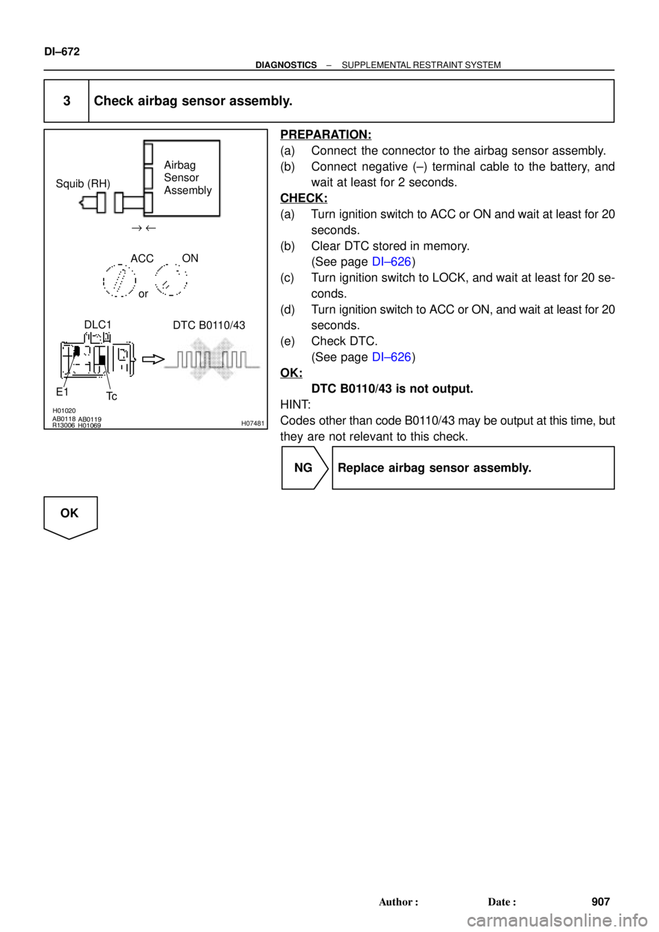
3 Check airbag sensor assembly.
PREPARATION:
(a) Connect the connector to the airbag sensor assembly.
(b) Connect negative (±) terminal cable to the battery, and
wait at least for 2 seconds.
CHECK:
(a) Turn ignition switch to ACC or ON and wait at least for 20
seconds.
(b) Clear DTC stored in memory.
(See page DI±626)
(c) Turn ignition switch to LOCK, and wait at least for 20 se-
conds.
(d) Turn ignition switch to ACC or ON, and wait at least for 20
seconds.
(e) Check DTC.
(See page DI±626)
OK:
DTC B0110/43 is not output.
HINT:
Codes other than code B0110/43 may be output at this time, but
they are not relevant to this check.
NG Replace airbag sensor assembly.
OK
Page 3093 of 4770

DTC B0110/43 DLC1
± DIAGNOSTICSSUPPLEMENTAL RESTRAINT SYSTEM
DI±673
908 Author�: Date�:
4 Check side squib (R")
H01021AB0118AB0119R13006H01069H01179
"u
E1
Tc ACC ON
orAirbag
Sensor
Assembly Squib (RH)
DTC B0110/43 DLC1
± DIAGNOSTICSSUPPLEMENTAL RESTRAINT SYSTEM
DI±673
908 Author�: Date�:
4 Check side squib (RH).
PREPARATION:
(a) Turn ignition switch to LOCK.
(b) Disconnect negative (±) terminal cable from the battery,
and wait at least for 90 seconds.
(c) Connect the side airbag assembly (RH) connector.
(d) Connect negative (±) terminal cable to the battery, and
wait at least for 2 seconds.
CHECK:
(a) Turn ignition switch to LOOK, and wait at least for 20 se-
cond.
(b) Turn ignition switch to ACC or ON, and wait at least for 20
seconds.
(c) Clear DTC stored in memory.
(See page DI±626)
(d) Turn ignition switch to LOCK, and wait at least for 20 se-
conds.
(e) Turn ignition switch to ACC or ON, and wait at least for 20
seconds.
(f) Check DTC.
(See page DI±626)
OK:
DTC B0110/43 is not output.
HINT:
Codes other than code B0110/43 may be output at this time, but
they are not relevant to this check.
NG Replace side airbag assembly (RH).
OK
From the results of the above inspection, the malfunctioning part can now be considered normal.
To make sure of this, use the simulation method to check.
Page 3094 of 4770
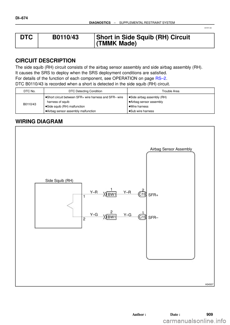
H04507
Side Squib (RH)Airbag Sensor Assembly
SFR+
SFR± Y±R
Y±G 1
21 2
C19
C19 Y±R
Y±G BW1
BW11
2 DI±674
± DIAGNOSTICSSUPPLEMENTAL RESTRAINT SYSTEM
909 Author�: Date�:
DTC B0110/43 Short in Side Squib (RH) Circuit
(TMMK Made)
CIRCUIT DESCRIPTION
The side squib (RH) circuit consists of the airbag sensor assembly and side airbag assembly (RH).
It causes the SRS to deploy when the SRS deployment conditions are satisfied.
For details of the function of each component, see OPERATION on page RS±2.
DTC B0110/43 is recorded when a short is detected in the side squib (RH) circuit.
DTC No.DTC Detecting ConditionTrouble Area
B0110/43
�Short circuit between SFR+ wire harness and SFR± wire
harness of squib
�Side squib (RH) malfunction
�Airbag sensor assembly malfunction�Side airbag assembly (RH)
�Airbag sensor assembly
�Wire harness
�Sub wire harness
WIRING DIAGRAM
DI1KY±02