Page 1087 of 4770
NEW FEATURES Ð BODY 6
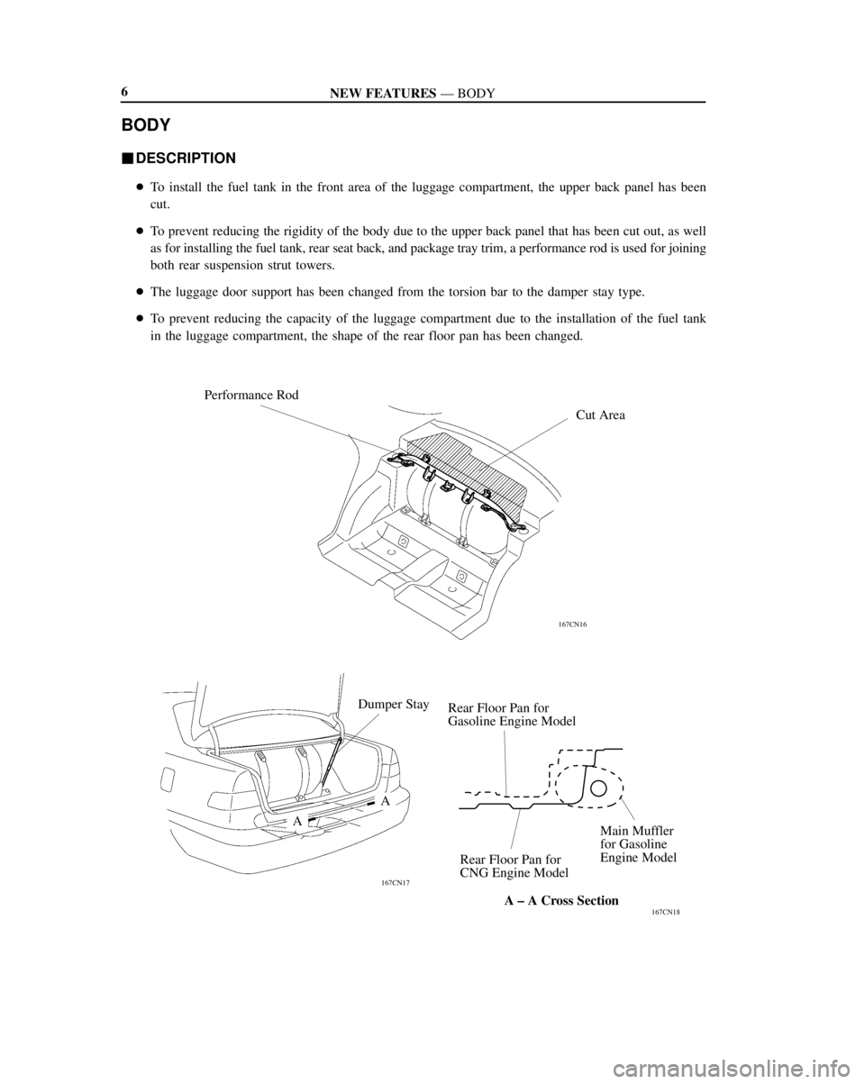
BODY
�DESCRIPTION
�To install the fuel tank in the front area of the luggage compartment, the upper back panel has been
cut.
�To prevent reducing the rigidity of the body due to the upper back panel that has been cut out, as well
as for installing the fuel tank, rear seat back, and package tray trim, a performance rod is used for joining
both rear suspension strut towers.
�The luggage door support has been changed from the torsion bar to the damper stay type.
�To prevent reducing the capacity of the luggage compartment due to the installation of the fuel tank
in the luggage compartment, the shape of the rear floor pan has been changed.
A ± A Cross Section
167CN16
Performance Rod
167CN17
167CN18
Cut Area
Dumper Stay
Rear Floor Pan for
Gasoline Engine Model
Main Muffler
for Gasoline
Engine Model
Rear Floor Pan for
CNG Engine Model
A
A
Page 1091 of 4770

Rear
Model Code
Front mm (in.)
Rear mm (in.)4-Door Sedan
ItemArea
Body Type
Vehicle Grade
OverallLength mm (in.)
Width mm (in.)
Height* mm (in.)
Wheel Base mm (in.)
Tread")
APPENDIX
Curb to Curb m (ft.)
Rear
Model Code
Front mm (in.)
Rear mm (in.)4-Door Sedan
ItemArea
Body Type
Vehicle Grade
OverallLength mm (in.)
Width mm (in.)
Height* mm (in.)
Wheel Base mm (in.)
Tread
Rear mm (in.)
Effective Head Room
Front mm (in.)
Overhang
Min. Running Ground Clearance mm (in.)
Angle of Approach degrees
Angle of Departure degrees
Curb Weight
Gross Vehicle WeightFront kg (lb)
Rear kg (lb)
Total kg (lb)
Front kg (lb)
Rear kg (lb)
Total kg (lb)
Fuel Tank Capacity (US.gal., Imp. gal)
Max. Speed km / h (mph)
Max. Cruising Speed km / h (mph)
Acceleration
Wall to Wall m (ft.) 0 to 100 km/h sec.
Valve Mechanism
Brake Type
Parking Brake Type
Brake Booster Type and Size in.
Proportioning Valve Type
Suspension Type
Stabilizer Bar
Steering Gear Type
Steering Gear Ratio (Overall)
Power Steering TypeFront
Front
Rear Front
Rear
5
10
15
20
25
30
35
40
45
50
55
60
65
70
Major Dimensions & Vehicle Weights Performance Chassis
U.S.A.
Shoulder Room
Front mm (in.)
Rear mm (in.)
Front mm (in.)
Rear mm (in.)
Front mm (in.)
Rear mm (in.) Effective Leg Room
Turning Diameter
(Outside Front)0 to 400 m sec.
Engine
Electrical
Engine Type
Bore � Stroke mm (in.)
Differential Gear Ratio (Final) Counter Gear RatioIn Fifth
In Reverse Transmission Gear
RatioIn Third
In Fourth In First
In Second
Clutch Type
Transaxle TypeStarter Output kW Generator Output Watts Battery Capacity (5HR) Voltage & Amp. hr. Carburetor Type Compression Ratio Displacement cm
3 (cu.in.)
Max. Torque (SAE-NET) N´m/rpm (lb-ft@rpm) Research Octane No. RON
Max. Output (SAE-NET) kW/rpm (HP@rpm)
Engine
3rd Gear km/h (mph)
4th Gear km/h (mph) 1st Gear km/h (mph)
2nd Gear km/h (mph)
Max. Permissible
Speed
Luggage Compartment Capacity
28
MAJOR TECHNICAL SPECIFICATIONS
LE
SXV23L-AEPNCA
4785 (188.4)
1780 (70.1)
1420 (55.9)
2670 (105.1)
1545 (60.8)
1520 (59.8)
980 (38.6)
940 (37.0)
1102 (43.4)
901 (35.5)
1427 (56.2)
1425 (56.1)
970 (38.2)
1140 (44.9)
130 (5.1)
165
165
860 (1896)
595 (1312)
1455 (3208)
970 (2140)
950 (2095)
1920 (4235)
135 (35.7, 29.2)*1, 43 (11.4. 9.5)*2
0.332 m3 *3, 8.921 ft3
*4
180 (112)
Ð
Ð
Ð
66 (41)
119 (74)
Ð
Ð
11.9 (39.0)
11.4 (37.4)
5S-FNE
16-Valve, DOHC
87.0 � 91.0 (3.43 � 3.58)
2164 (132.0)
11.0 : 1
SFI
130
88/5200 (118/5200)
178/2400 (131/2400)
12 ± 55
960
1.4
Ð
A140E
2.810
1.549
1.000
0.706
Ð
2.296
0.945
4.176
Ventilated Disc
L.T. Drum
Drum
Tandem 8º + 9º
Dual-P Valve
MacPherson Strut
MacPherson Strut
STD
STD
Rack and Pinion
17.4 : 1
Integral Type
*: Unladed Vehicle
*
1: Water Volume
*2: Equivalent Gasoline Capacity
*3: VDA
*4: SAE Suitcase
Page 1112 of 4770

SCHEDULED MAINTENANCE LOGS20
The following descriptions are provided to give you a better
understanding of the maintenance items that should be per-
formed on your vehicle. The Scheduled Maintenance Log
indicates at which mileage/time intervals each item should be
performed. Please note that many maintenance items should be
performed only by a qualified technician.
For further information on maintenance items you can per-
form yourself, see the “General Maintenance and Care” and
“Do- It-Yourself Maintenance” sections of your
Owner’s Manual.
Automatic Transmission Fluid
or Manual Transmission Oil
Inspect each component for signs of leakage. If you discover any
leakage, have it repaired by a qualified technician immediately.
Ball Joints and Dust Covers
Check the suspension and steering linkage ball joints for loose-
ness and damage. Check all dust covers for deterioration and
damage. A qualified technician should perform these inspections.
Brake Lines and Hoses
Visually inspect for proper installation. Check for chafing,
cracks, deterioration and evidence of leaking. Replace any deteri-
orated or damaged parts immediately. A qualified technician
should perform these operations.
Explanation of Maintenance Items
Page 1114 of 4770

SCHEDULED MAINTENANCE LOGS22Engine Valves
Inspect for excessive lifter noise and engine vibration and adjust if
necessary. A qualified technician should perform this operation.
Exhaust Pipes and Mountings
Visually inspect the exhaust pipes, muffler and hangers for
cracks, deterioration and damage. Start the engine and listen
carefully for any exhaust gas leakage. Tighten connections or
replace parts as necessary.
Fuel Lines and Connections, Fuel Tank Band
and Fuel Tank Vapor Vent System Hoses
Visually inspect for corrosion, damage, cracks and loose or leaking
connections. Tighten connections or replace parts as necessary.
Fuel Tank Cap Gasket
Visually inspect for cracks, deterioration and damage and
replace if necessary.
Nuts and Bolts on Chassis and Body
Re- tighten the seat mounting bolts and front/rear suspension
member retaining bolts to specified torque.
Propeller Shaft
Lubricate the propeller shaft spiders and slide yokes with
lithium- base chassis grease and the double cardan joint with
molybdenum- disulfide lithium- base chassis grease, and re-
torque the flange bolts. Only a qualified technician should
re- torque the flange bolts.
Spark Plugs
Install new plugs of the same type as originally equipped. A
qualified technician should perform this operation.
Steering Gear Box
Inspect for signs of leakage. If you discover any leakage, have it
repaired immediately by a qualified technician.
Explanation of Maintenance Items
Page 1642 of 4770
AUTOMATIC TRANSAXLEPREPARATION ±
AX±9
(09351±32111)Side Bearing Race Replacer
(09351±32120)Overdrive Bearing Replacer
(09351±32130)Handle
(09351±32140)Oil Seal Replacer
(09351±32150)Oil Seal Replacer
(09351±32190)Measure Terminal
(09351±32200)No.3 Piston Spring Compressor
09502±10012Differential Side Bearing Puller
�
09564±32011Differential Preload Adaptor
09710±28020Front Suspension Bushing Tool
Set�
(09710±08040)Bushing Replacer�
09950±00020Bearing Remover
RECOMMENDED TOOL
09031±00030Pin Punch .
AX0ER±02
Page 1776 of 4770
RH Rear
Lower Brace
Steering Return Pipe
19 (195, 14)
FR Engine Mounting
Stabilizer Bar Link
Front Suspension
Member
�
Front Ex")
Q10054
RH Fender Apron seal
RR Engine Mounting
Stabilizer Bar
10 (100, 7)RH Rear
Lower Brace
Steering Return Pipe
19 (195, 14)
FR Engine Mounting
Stabilizer Bar Link
Front Suspension
Member
�
Front Exhaust Pipe
RH Front Lower Brace
LH Engine Mounting
66 (670, 48)
64 (650, 47)
39 (400, 29)
181 (1,850, 134)
LH Rear Lower Brace
32 (330, 24)
36 (370, 27)
181 (1,850, 134)
127 (1,300, 94)80 (820, 59)
TMC Made : 80 (820, 59)
TMMK Made :
Green Color Bolt : 66 (670, 48)
Silver Color Bolt : 44 (450, 32)
TMC Made : 80 (820, 59)
TMMK Made :
Green Color Bolt : 66 (670, 48)
Silver Color Bolt : 44 (450, 32)LH Front
Lower Brace
36 (370, 27)181 (1,850, 134)
56 (570, 41)
�
�� � Gasket
62 (630, 46)
Tie Rod End
Lock Nut Cap
Engine Under CoverLH Fender Liner � Gasket
�
Exhaust Pipe No.1 Support Bracket
33 (330, 24)
33 (330, 24)
Exhaust Pipe
ClampLH Fender Liner
LH Fender Apron Seal
� Cotter Pin
49 (500, 36)
294 (3,000, 217)
Center Engine Under Cover
N´m (kgf´cm, ft´lbf): Specified torque
� Non±reusable part AX±18
± AUTOMATIC TRANSAXLE (A140E)AUTOMATIC TRANSAXLE UNIT
1911 Author�: Date�:
Page 3458 of 4770
A02188
Engine Moving Control Rod
Engine and
Transaxle Assembly
Front Engine
Mounting Insulator
RH Drive Shaft
Lower Suspension ArmLH Drive Shaft No.2 RH Engine
Mounting BracketRear Engine
mounting
Insulator
Transaxle
Shift
Control
Cable
(A/T)
Tie Rod End
Lock CapTransaxle Shift
Control Cable
Clutch Release Cylinder and Tube Engine Wire
��Starter M/T
N´m (kgf´cm, ft´lbf)
64 (650, 47)
64 (650, 47)
127 (1,300, 94)
52 (530, 38)
64 (650, 47)
66 (670, 49)
49 (500, 36)
64 (650, 47)
64 (650, 47)
64 (650, 47)
294 (3,000, 217)
TMC Made
80 (820, 59)
TMMK Made
44 (450, 32) for Silver Color
66 (670, 49) for Green Color
: Specified torque
� Non±reusable part
EM±66
± ENGINE MECHANICAL (5S±FE)ENGINE UNIT
1238 Author�: Date�:
Page 3576 of 4770
A06646
RH Drive Shaft
LH Drive Shaft
Tie Rod End
49 (500, 36)
294 (3,000, 217)64 (650, 47)32 (320, 23)
RH Engine
Mounting Stay
Lower Suspension Arm Engine Moving
Control Rod
64 (650, 47)
127 (1,300, 94)
No.2 RH Engine
Mounting Stay (M/T)
No.2 RH Engine
Mounting Bracket
Engine and Transaxle
Assembly
64 (650, 47)
66 (670, 48)
64 (650, 47)
Front Engine
Mounting Insulator
48 (490, 35)
64 (650, 47)
Transaxle
Control Cable
Engine Mounting Absorber
TMC Made 80 (820,59)
TMMK Made
Green Clolr Bolt 66 (670, 48)
Silver Clolr Bolt 44 (450,32)
N´m (kgf´cm, ft´lbf) : Specified torque
� Non±reusable part�
Rear Engine
Mounting
Insulator
EM±70
± ENGINE MECHANICAL (1MZ±FE)ENGINE UNIT
1356 Author�: Date�:
Side Bearing Race Replacer
(09351±32120)Overdrive Bearing Replacer
(09351±32130)Handle
(09351±32140)Oil Seal Replacer
(09351±32150)Oil Seal Re")


294 (3,000, 217)64 (650, 47)32 (320, 23)
RH Engine
Mounting Stay
Lower Suspension Arm Engine Moving
Control Rod
64 (650, 47)
127 (1,300, 9")