Page 1091 of 4770

APPENDIX
Curb to Curb m (ft.)
Rear
Model Code
Front mm (in.)
Rear mm (in.)4-Door Sedan
ItemArea
Body Type
Vehicle Grade
OverallLength mm (in.)
Width mm (in.)
Height* mm (in.)
Wheel Base mm (in.)
Tread
Rear mm (in.)
Effective Head Room
Front mm (in.)
Overhang
Min. Running Ground Clearance mm (in.)
Angle of Approach degrees
Angle of Departure degrees
Curb Weight
Gross Vehicle WeightFront kg (lb)
Rear kg (lb)
Total kg (lb)
Front kg (lb)
Rear kg (lb)
Total kg (lb)
Fuel Tank Capacity (US.gal., Imp. gal)
Max. Speed km / h (mph)
Max. Cruising Speed km / h (mph)
Acceleration
Wall to Wall m (ft.) 0 to 100 km/h sec.
Valve Mechanism
Brake Type
Parking Brake Type
Brake Booster Type and Size in.
Proportioning Valve Type
Suspension Type
Stabilizer Bar
Steering Gear Type
Steering Gear Ratio (Overall)
Power Steering TypeFront
Front
Rear Front
Rear
5
10
15
20
25
30
35
40
45
50
55
60
65
70
Major Dimensions & Vehicle Weights Performance Chassis
U.S.A.
Shoulder Room
Front mm (in.)
Rear mm (in.)
Front mm (in.)
Rear mm (in.)
Front mm (in.)
Rear mm (in.) Effective Leg Room
Turning Diameter
(Outside Front)0 to 400 m sec.
Engine
Electrical
Engine Type
Bore � Stroke mm (in.)
Differential Gear Ratio (Final) Counter Gear RatioIn Fifth
In Reverse Transmission Gear
RatioIn Third
In Fourth In First
In Second
Clutch Type
Transaxle TypeStarter Output kW Generator Output Watts Battery Capacity (5HR) Voltage & Amp. hr. Carburetor Type Compression Ratio Displacement cm
3 (cu.in.)
Max. Torque (SAE-NET) N´m/rpm (lb-ft@rpm) Research Octane No. RON
Max. Output (SAE-NET) kW/rpm (HP@rpm)
Engine
3rd Gear km/h (mph)
4th Gear km/h (mph) 1st Gear km/h (mph)
2nd Gear km/h (mph)
Max. Permissible
Speed
Luggage Compartment Capacity
28
MAJOR TECHNICAL SPECIFICATIONS
LE
SXV23L-AEPNCA
4785 (188.4)
1780 (70.1)
1420 (55.9)
2670 (105.1)
1545 (60.8)
1520 (59.8)
980 (38.6)
940 (37.0)
1102 (43.4)
901 (35.5)
1427 (56.2)
1425 (56.1)
970 (38.2)
1140 (44.9)
130 (5.1)
165
165
860 (1896)
595 (1312)
1455 (3208)
970 (2140)
950 (2095)
1920 (4235)
135 (35.7, 29.2)*1, 43 (11.4. 9.5)*2
0.332 m3 *3, 8.921 ft3
*4
180 (112)
Ð
Ð
Ð
66 (41)
119 (74)
Ð
Ð
11.9 (39.0)
11.4 (37.4)
5S-FNE
16-Valve, DOHC
87.0 � 91.0 (3.43 � 3.58)
2164 (132.0)
11.0 : 1
SFI
130
88/5200 (118/5200)
178/2400 (131/2400)
12 ± 55
960
1.4
Ð
A140E
2.810
1.549
1.000
0.706
Ð
2.296
0.945
4.176
Ventilated Disc
L.T. Drum
Drum
Tandem 8º + 9º
Dual-P Valve
MacPherson Strut
MacPherson Strut
STD
STD
Rack and Pinion
17.4 : 1
Integral Type
*: Unladed Vehicle
*
1: Water Volume
*2: Equivalent Gasoline Capacity
*3: VDA
*4: SAE Suitcase
Page 2977 of 4770

± DIAGNOSTICSANTI±LOCK BRAKE SYSTEM (BOSCH Made)
DI±557
792 Author�: Date�:
DTC 37 Speed Sensor Rotor Faulty
CIRCUIT DESCRIPTION
DTC No.DTC Detecting ConditionTrouble Area
37
Detection of any of conditions from 1. through 3.:
1. Occurrence of differential to some degree in the wheel
speed between the front and rear wheels of either left or
right side of the vehicle and the front left and right
wheels. (Detection of differential in mini tire size, spin-
ning wheel and decelerating wheel.)
2. Continuous ABS control for 60 sec. or more.
3. Interference on 1 or more wheels for 20 sec. with the
brake pedal depressed, or for 5 sec. when the brake
pedal is not depressed.
�Speed sensor
�Sensor rotor
�ECU
INSPECTION PROCEDURE
1 Check sensor rotor (See page DI±552).
NG Replace sensor rotor.
OK
2 Check speed sensor (See page DI±552).
NG Replace speed sensor.
OK
3 Check for open and short circuit in harness and connector between speed sen-
sor and ECU (See page IN±31).
NG Repair or replace harness and connector.
OK
Check and replace ABS ECU.
DI044±04
Page 3710 of 4770

± INTRODUCTIONTERMS
IN±39
39 Author�: Date�:
OHVOverhead Valve
OPTOption
O/SOversize
P & BVProportioning And Bypass Valve
PCSPower Control System
PCVPositive Crankcase Ventilation
PKBParking Brake
PPSProgressive Power Steering
PSPower Steering
PTOPower Take±Off
R & PRack And Pinion
R/BRelay Block
RBSRecirculating Ball Type Steering
R/FReinforcement
RFSRigid Front Suspension
RRSRigid Rear Suspension
RHRight±Hand
RHDRight±Hand Drive
RLYRelay
ROMRead Only Memory
RrRear
RRRear±Engine Rear±Wheel Drive
RWDRear±Wheel Drive
SDNSedan
SENSensor
SICSStarting Injection Control System
SOCState Of Charge
SOHCSingle Overhead Camshaft
SPECSpecification
SPISingle Point Injection
SRSSupplemental Restraint System
SSMSpecial Service Materials
SSTSpecial Service Tools
STDStandard
STJCold±Start Fuel Injection
SWSwitch
SYSSystem
T/ATransaxle
TACHTachometer
TBIThrottle Body Electronic Fuel Injection
TCTurbocharger
TCCSTOYOTA Computer±Controlled System
TCVTiming Control Valve
TDCTop Dead Center
TEMP.Temperature
TEMSTOYOTA Electronic Modulated Suspension
Page 3711 of 4770
IN±40
± INTRODUCTIONTERMS
40 Author�: Date�:
TISTotal Information System For Vehicle Development
T/MTransmission
TMCTOYOTA Motor Corporation
TMMKTOYOTA Motor Manufacturing Kentucky, Inc.
TRACTraction Control System
TURBOTurbocharge
U/DUnderdrive
U/SUndersize
VCVVacuum Control Valve
VENTVentilator
VINVehicle Identification Number
VPSVariable Power Steering
VSCVehicle Skid Control Vehicle Stability Control
VSVVacuum Switching Valve
VTVVacuum Transmitting Valve
w/With
WGNWagon
W/HWire Harness
w/oWithout
1stFirst
2ndSecond
2WDTwo Wheel Drive Vehicle (4x2)
4WDFour Wheel Drive Vehicle (4x4)
Page 4193 of 4770

RS011±19
AB0152
SST RS±18
± SUPPLEMENTAL RESTRAINT SYSTEMSTEERING WHEEL PAD AND SPIRAL CABLE
2163 Author�: Date�:
DISPOSAL
HINT:
When scrapping vehicle equipped with an SRS or disposing of
a steering wheel pad (with airbag), always first deploy the air-
bag in accordance with the procedure described below. If any
abnormality occurs with the airbag deployment, contact the
SERVICE DEPT. of TOYOTA MOTOR SALES, U.S.A., INC.
When disposing of a steering wheel pad with an airbag
deployed in a collision, follow the same procedure given in step
1±(d) in ºDISPOSALº.
CAUTION:
�Never dispose of a steering wheel pad which has an
undeployed airbag.
�The airbag produces a sizeable exploding sound
when it deploys, so perform the operation out±of±
doors and where it will not create a nuisance to
nearby residents.
�When deploying the airbag, always use the specified
SST (SRS Airbag Deployment Tool). Perform the op-
eration in a place away from electrical noise.
SST 09082±00700
�When deploying an airbag, perform the operation at
least 10 m (33 ft) away from the steering wheel pad.
�The steering wheel pad is very hot when the airbag is
deployed, so leave it alone for at least 30 minutes af-
ter deployment.
�Use gloves and safety glasses when handling a steer-
ing wheel pad with the deployed airbag.
�Always wash your hands with water after completing
the operation.
�Do not apply water, etc. to a steering wheel pad with
the deployed airbag.
Page 4198 of 4770

H06696
SST
H00401Weight
x y
y
R04211
Inner Diam.
Tires
(3 or More)Width
± SUPPLEMENTAL RESTRAINT SYSTEMSTEERING WHEEL PAD AND SPIRAL CABLE
RS±23
2168 Author�: Date�:
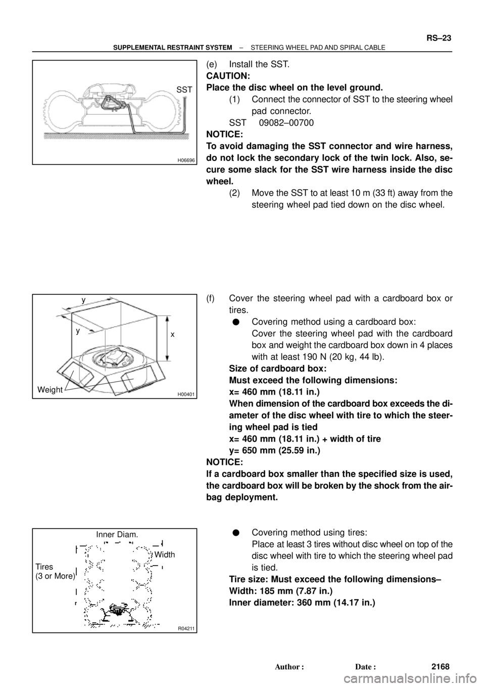
(e) Install the SST.
CAUTION:
Place the disc wheel on the level ground.
(1) Connect the connector of SST to the steering wheel
pad connector.
SST 09082±00700
NOTICE:
To avoid damaging the SST connector and wire harness,
do not lock the secondary lock of the twin lock. Also, se-
cure some slack for the SST wire harness inside the disc
wheel.
(2) Move the SST to at least 10 m (33 ft) away from the
steering wheel pad tied down on the disc wheel.
(f) Cover the steering wheel pad with a cardboard box or
tires.
�Covering method using a cardboard box:
Cover the steering wheel pad with the cardboard
box and weight the cardboard box down in 4 places
with at least 190 N (20 kg, 44 lb).
Size of cardboard box:
Must exceed the following dimensions:
x= 460 mm (18.11 in.)
When dimension of the cardboard box exceeds the di-
ameter of the disc wheel with tire to which the steer-
ing wheel pad is tied
x= 460 mm (18.11 in.) + width of tire
y= 650 mm (25.59 in.)
NOTICE:
If a cardboard box smaller than the specified size is used,
the cardboard box will be broken by the shock from the air-
bag deployment.
�Covering method using tires:
Place at least 3 tires without disc wheel on top of the
disc wheel with tire to which the steering wheel pad
is tied.
Tire size: Must exceed the following dimensions±
Width: 185 mm (7.87 in.)
Inner diameter: 360 mm (14.17 in.)
Page 4342 of 4770

R03031
SA078±01
R15157
Front
R07928
SA±2
± SUSPENSION AND AXLETIRE AND WHEEL
1953 Author�: Date�:
TIRE AND WHEEL
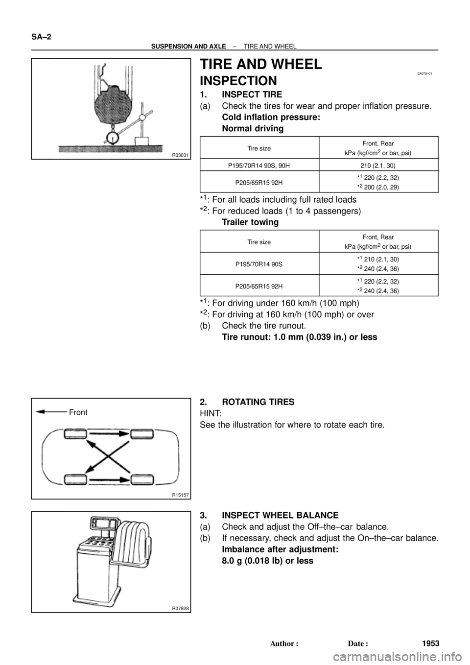
INSPECTION
1. INSPECT TIRE
(a) Check the tires for wear and proper inflation pressure.
Cold inflation pressure:
Normal driving
Tire sizeFront, Rear
kPa (kgf/cm2 or bar, psi)
P195/70R14 90S, 90H210 (2.1, 30)
P205/65R15 92H*1 220 (2.2, 32)
*2 200 (2.0, 29)
*1: For all loads including full rated loads
*
2: For reduced loads (1 to 4 passengers)
Trailer towing
Tire sizeFront, Rear
kPa (kgf/cm2 or bar, psi)
P195/70R14 90S*1 210 (2.1, 30)
*2 240 (2.4, 36)
P205/65R15 92H*1 220 (2.2, 32)
*2 240 (2.4, 36)
*1: For driving under 160 km/h (100 mph)
*
2: For driving at 160 km/h (100 mph) or over
(b) Check the tire runout.
Tire runout: 1.0 mm (0.039 in.) or less
2. ROTATING TIRES
HINT:
See the illustration for where to rotate each tire.
3. INSPECT WHEEL BALANCE
(a) Check and adjust the Off±the±car balance.
(b) If necessary, check and adjust the On±the±car balance.
Imbalance after adjustment:
8.0 g (0.018 lb) or less
Page 4344 of 4770

W03085
Front
R03030
Rear
SA079±01
Z03382
SA3213
AB
C D
Front SA±4
± SUSPENSION AND AXLEFRONT WHEEL ALIGNMENT
1955 Author�: Date�:
FRONT WHEEL ALIGNMENT
INSPECTION
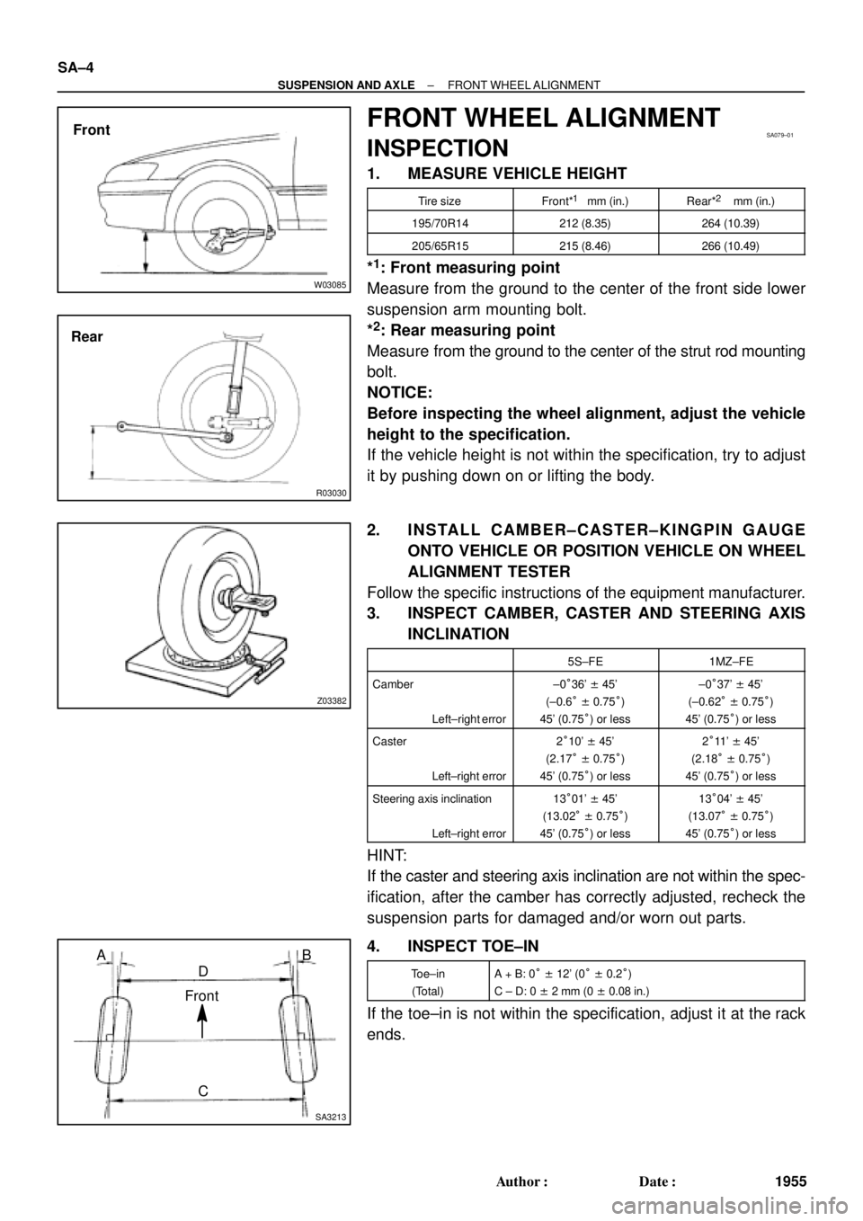
1. MEASURE VEHICLE HEIGHT
Tire sizeFront*1 mm (in.)Rear*2 mm (in.)
195/70R14212 (8.35)264 (10.39)
205/65R15215 (8.46)266 (10.49)
*1: Front measuring point
Measure from the ground to the center of the front side lower
suspension arm mounting bolt.
*
2: Rear measuring point
Measure from the ground to the center of the strut rod mounting
bolt.
NOTICE:
Before inspecting the wheel alignment, adjust the vehicle
height to the specification.
If the vehicle height is not within the specification, try to adjust
it by pushing down on or lifting the body.
2. INSTALL CAMBER±CASTER±KINGPIN GAUGE
ONTO VEHICLE OR POSITION VEHICLE ON WHEEL
ALIGNMENT TESTER
Follow the specific instructions of the equipment manufacturer.
3. INSPECT CAMBER, CASTER AND STEERING AXIS
INCLINATION
5S±FE1MZ±FE
Camber
Left±right error±0°36' ± 45'
(±0.6° ± 0.75°)
45' (0.75°) or less±0°37' ± 45'
(±0.62° ± 0.75°)
45' (0.75°) or less
Caster
Left±right error2°10' ± 45'
(2.17° ± 0.75°)
45' (0.75°) or less2°11' ± 45'
(2.18° ± 0.75°)
45' (0.75°) or less
Steering axis inclination
Left±right error13°01' ± 45'
(13.02° ± 0.75°)
45' (0.75°) or less13°04' ± 45'
(13.07° ± 0.75°)
45' (0.75°) or less
HINT:
If the caster and steering axis inclination are not within the spec-
ification, after the camber has correctly adjusted, recheck the
suspension parts for damaged and/or worn out parts.
4. INSPECT TOE±IN
Toe±in
(Total)A + B: 0° ± 12' (0° ± 0.2°)
C ± D: 0 ± 2 mm (0 ± 0.08 in.)
If the toe±in is not within the specification, adjust it at the rack
ends.