Page 3013 of 4770

BR3583
BR3582F00010
RotorSpeed Sensor
Magnet
To ECU
+V
±VHigh Speed
Low Speed
CoilNS
± DIAGNOSTICSABS & TRACTION CONTROL SYSTEM
DI±593
828 Author�: Date�:
DTC31, 32, 33, 34Speed Sensor Circuit
CIRCUIT DESCRIPTION
The speed sensor detects wheel speed and sends the ap-
propriate signals to the ECU. These signals are used to control
the ABS and TRAC system. The front and rear rotors each have
48 serrations.
When the rotors rotate, the magnetic field emitted by the perma-
nent magnet in the speed sensor generates an AC voltage.
Since the frequency of this AC voltage changes in direct propor-
tion to the speed of the rotor, the frequency is used by the ECU
to detect the speed of each wheel.
DTC No.DTC Detecting ConditionTrouble Area
31, 32, 33, 34
Detection of any of conditions from 1. through 3.:
1. ABS is in non±operation, wheel speed is 10 km/h or
more, one eighth of maximum wheel speed is greater
than the minimum wheel speed, one eighth of maximum
wheel speed is smaller than the rear maximum wheel
speed or momentary interruption of both the rear wheels
are shown in the 15 sec. or more continuously.
2. ABS is in non±operation, momentary interruption of
speed sensor occurs 7 times or more in the mean time
of switching the ignition switch ON and OFF or vehicle
speed is 20 km/h (12 mph) or more and the condition of
noise interference or non±noise interference occurs 75
times or more within 5 sec.
3. Vehicle is at a stop, malfunction signal of vehicle speed
sensor hardware open circuit is ON for 1.02 sec. contin-
uously since starting the checking of a certain vehicle.
�Right front, left front, right rear, left rear speed sensor
�Each speed sensor circuit
�Speed sensor rotor
�ECU
HINT:
�DTC No. 31 is for the right front speed sensor.
�DTC No. 32 is for the left front speed sensor.
�DTC No. 33 is for the right rear speed sensor.
�DTC No. 34 is for the left rear speed sensor.
Fail safe function:
If any trouble occurs in the speed sensor circuit, the ECU cuts off current to the ABS & TRAC solenoid relay
and prohibits ABS control and TRAC control.
DI1JP±03
Page 3018 of 4770

F00175
Battery MAIN FL Block
B±G 1K2Ignition
Switch
Instrument Panel J/B
1B
F4 F91A16
GND3
B±R
1Instrument Panel J/B
1
A15 B±YJ/C
4B±R
CABS & TRAC ECU
9
A17 1JJ12
IG1
W±B W
GND1
GND2 21K1
CB±R
A17 W±B
W±B
EA8
15
109
W±B
W±B
Battery MAIN FL Block
B±G 1K2Ignition
Switch
Instrument Panel J/B
1B
F4 F91A16
GND3
B±R
1Instrument Panel J/B
1
A15 B±YJ/C
4B±R
CABS & TRAC ECU
9
A17 1JJ12
IG1
W±B W
GND1
GND2 21K1
CB±R
A17 W±B
W±B
EA8
15
109
W±B
W±B
Battery MAIN FL Block
B±G 1K2Ignition
Switch
Instrument Panel J/B
1B
F4 F91A16
GND3
B±R
1Instrument Panel J/B
1
A15 B±YJ/C
4B±R
CABS & TRAC ECU
9
A17 1JJ12
IG1
W±B W
GND1
GND2 21K1
CB±R
A17 W±B
W±B
EA8
15
109
W±B
W±B
Battery MAIN FL Block
B±G 1K2Ignition
Switch
Instrument Panel J/B
1B
F4 F91A16
GND3
B±R
1Instrument Panel J/B
1
A15 B±YJ/C
4B±R
CABS & TRAC ECU
9
A17 1JJ12
IG1
W±B W
GND1
GND2 21K1
CB±R
A17 W±B
W±B
EA8
15
109
W±B
W±BBattery MAIN FL Block
ALT
B±GAM1 1K2Ignition
Switch
Instrument Panel J/B
1B
F4 F91A16
GND3
B±R
1Instrument Panel J/B
1
A15 B±YJ/C
ECU±IG 4B±R
CABS & TRAC ECU
9
A17 1JJ12
IG1
W±B W
GND1
GND2 21K1
CB±R
A17 W±B
W±B
EA8
15
109
W±B
W±B DI±598
± DIAGNOSTICSABS & TRACTION CONTROL SYSTEM
833 Author�: Date�:
DTC 41 IG Power Source Circuit
CIRCUIT DESCRIPTION
This is the power source for the ECU, hence the actuators.
DTC No.DTC Detecting ConditionTrouble Area
41
Detection of any conditions from 1. through 3.:
1. Vehicle speed is 3 km/h (1.9 mph) or more and battery
voltage is less than 9.5 V continues for 10 sec. or more.
2. Battery voltage has never exceeded more than 17.0 V
and has become less than 9.5 V within 2.16 sec., under
malfunction of solenoid relay monitor after the solenoid
relay is ON, at ECU AST terminal voltage of ECU has
become 8.0 V or more or under malfunction of motor
relay monitor and after the motor relay is ON, motor
relay monitor has become ON.
3. Battery voltage is more than 17.0 V , which continues for
1.2 sec. or more or battery voltage has become more
than 17.0 V within 2.16 sec. and solenoid or motor relay
monitor is under malfunction condition.
�Battery
�Charging system
�Power source circuit
�ECU
Fail safe function:
If any trouble occurs in the power source circuit, the ECU cuts off current to the ABS & TRAC solenoid relay
and prohibits ABS control and TRAC control.
WIRING DIAGRAM
DI04N±04
Page 3020 of 4770
F00058
IG1
GND ON
(+)
(±)IG1
GND ON
(+)
(±)IG1
GND ON
(+)
(±)IG1
GND ON
(+)
(±)
F07003
(+)(±) LOCK
GND
DI±600
± DIAGNOSTICSABS & TRACTION CONTROL SYSTEM
835 Author�: Date�:
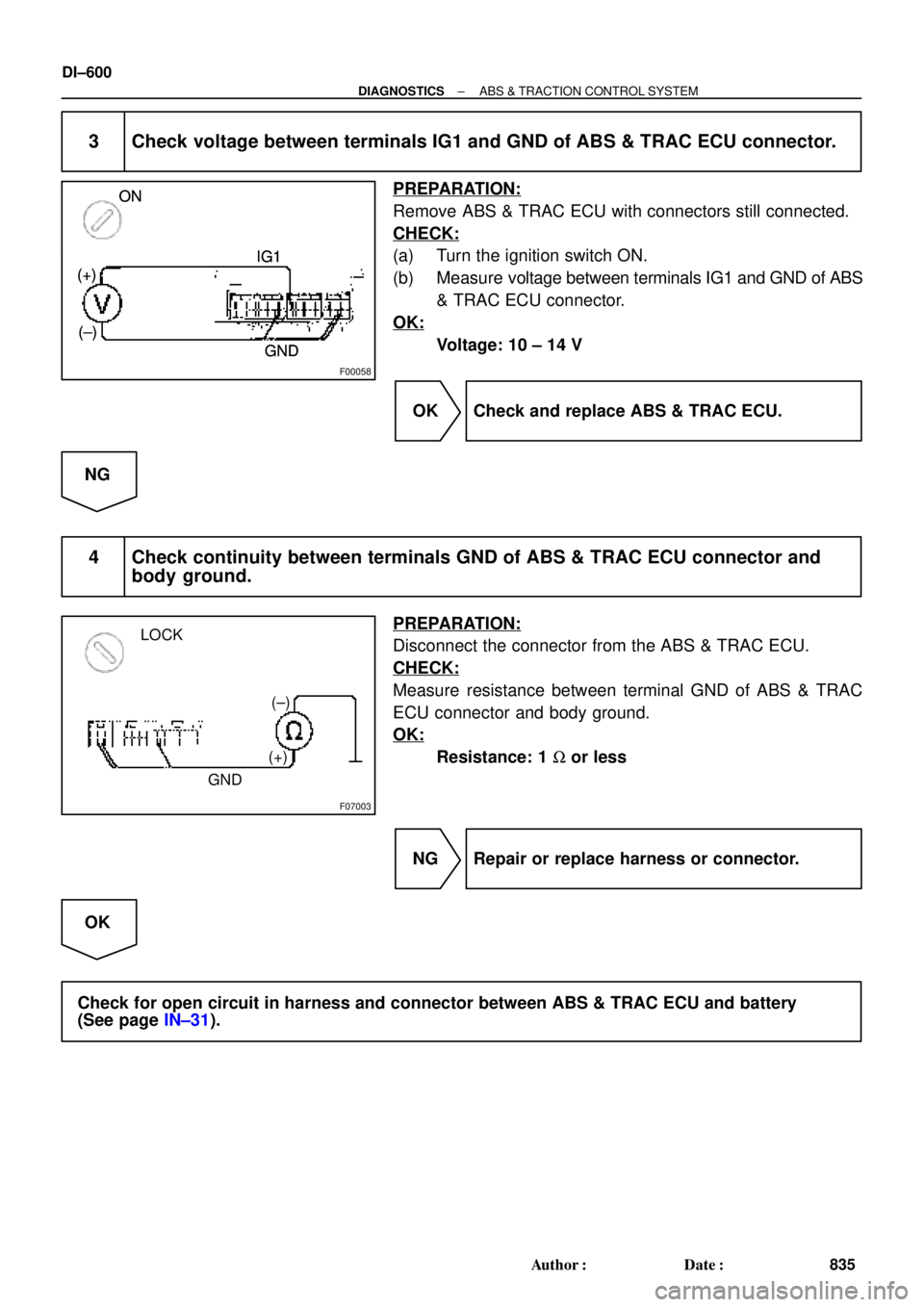
3 Check voltage between terminals IG1 and GND of ABS & TRAC ECU connector.
PREPARATION:
Remove ABS & TRAC ECU with connectors still connected.
CHECK:
(a) Turn the ignition switch ON.
(b) Measure voltage between terminals IG1 and GND of ABS
& TRAC ECU connector.
OK:
Voltage: 10 ± 14 V
OK Check and replace ABS & TRAC ECU.
NG
4 Check continuity between terminals GND of ABS & TRAC ECU connector and
body ground.
PREPARATION:
Disconnect the connector from the ABS & TRAC ECU.
CHECK:
Measure resistance between terminal GND of ABS & TRAC
ECU connector and body ground.
OK:
Resistance: 1 W or less
NG Repair or replace harness or connector.
OK
Check for open circuit in harness and connector between ABS & TRAC ECU and battery
(See page IN±31).
Page 3023 of 4770
F00061
NEO (+) (±) ON
F00011
(Reference)
3 ± 6 V
Below 1 V
3 ms. 3 ms. (Reference)
3 ± 6 V
Below 1 V
3 ms. 3 ms.(Reference)
3 ± 6 V
Below 1 V
3 ms. 3 ms.
± DIAGNOSTICSABS & TRACTION CONTROL SYSTEM
DI±603
838 Author�: Date�:
2 Check voltage between terminal NEO of ABS & TRAC ECU and body ground.
PREPARATION:
(a) Remove ABS & TRAC ECU with connectors still con-
nected.
(b) Turn ignition switch ON.
CHECK:
Measure voltage between terminal NEO of ABS & TRAC ECU
and body ground for the engine conditions below.
OK:
Engine conditionVoltage
OFF (IG ON)3 ± 6 V or below 1 V
ON (Idling)2 ± 3 V (Pulse)
NG Check and replace ABS & TRAC ECU or ECM.
OK
If the same code is still output after the DTC is deleted, check the contact condition of each con-
nection.
Page 3031 of 4770
± DIAGNOSTICSABS & TRACTION CONTROL SYSTEM
DI±611
846 Author�: Date�:
4 Check battery positive voltage.
CHECK:
Check the battery positive voltage.
OK:
10 ± 14 V
NG Check and repair the charging system
5S±FE engine: (See page CH±1)
1MZ±FE engine: (See page CH±1).
OK
5 Check ABS warning light.
PREPARATION:
(a) Disconnect the connector from the ABS & TRAC ECU.
(b) Turn the ignition switch ON.
CHECK:
Check the ABS warning light goes off.
OK Check and replace ABS & TRAC ECU.
NG
Check for short circuit in harness and connector between ABS warning light, DLC1, DLC2, and
ABS & TRAC ECU (See page IN±31)
Page 3035 of 4770
F00095
R±Y
3DLC1
J/CE1
ATs
J2211
II3 IK25
EC BRA15 BR
AR±Y
R±Y23 ABS & TRAC ECU
Ts
R±Y
3DLC1
J/CE1
ATs
J2211
II3 IK25
EC BRA15 BR
AR±Y
R±Y23 ABS & TRAC ECU
Ts
16
AB0119S08096
F00446
Ts
DLC1
E1
ON
± DIAGNOSTICSABS & TRACTION CONTROL SYSTEM
DI±615
850 Author�: Date�:
Ts Terminal Circuit
CIRCUIT DESCRIPTION
The sensor check circuit detects abnormalities in the speed sensor signal which cannot be detected with
the DTC check.
Connecting terminals Ts and E
1 of the DLC1 in the engine compartment starts the check.
WIRING DIAGRAM
INSPECTION PROCEDURE
1 Check voltage between terminals Ts and E1 of DLC1.
CHECK:
(a) Turn the ignition switch ON.
(b) Measure voltage between terminals Ts and E
1 of DLC1.
OK:
Voltage: 10 ± 14 V
OK If ABS warning light does not blink even after Ts
and E
1 are connected, the ECU may be defec-
tive.
NG
DI04X±04
Page 3041 of 4770
F00120
DLC2
ECII3
ADLC1 6
12
Tc
BJ3
J22J/C
II3A15 IK2 J8
11 J7 E
1
C
BRA
ABR BRBRJ/C
BR
TcTc
E
1LG±RJ/C
BB B LG±R LG±RLG±RABS & TRAC ECU
9
34
113
DLC2
ECII3
ADLC1 6
12
Tc
BJ3
J22J/CLG±R
*1
II3A15 IK2 J8
11 J7 E
1
C
BRA
ABR BRBRJ/C
BR
TcTc
E
1LG±RJ/C
BB B LG±R LG±RLG±RABS & TRAC ECU
9
34
113
P±B*2
*1:
TMC Made*2: TMMK Made
F02607 F00445F02612
DLC2
DLC1
Tc E
1
Tc E
1
± DIAGNOSTICSABS & TRACTION CONTROL SYSTEM
DI±621
856 Author�: Date�:
Tc Terminal Circuit
CIRCUIT DESCRIPTION
Connecting between terminals Tc and E1 of the DLC1 or the DLC2 causes the ECU to display the DTC by
blinking the ABS warning light and TRAC OFF indicator light.
WIRING DIAGRAM
INSPECTION PROCEDURE
1 Check voltage between terminals Tc and E1 of DLC2 or DLC1.
CHECK:
(a) Turn the ignition switch ON.
(b) Measure voltage between terminals Tc and E
1 of DLC2 or
DLC1.
OK:
Voltage: 10 ± 14 V
OK If ABS warning light does not blink even after Tc
and E
1 are connected, the ECU may be defec-
tive.
NG
DI4KY±01
Page 3046 of 4770
 Turn the ignition switch to the ACC or ON position")
DI4L1±01
H02309
R13006
DLC1
E1 Tc
DI±626
± DIAGNOSTICSSUPPLEMENTAL RESTRAINT SYSTEM
861 Author�: Date�:
PRE±CHECK
1. SRS WARNING LIGHT CHECK
(a) Turn the ignition switch to the ACC or ON position and
check that the SRS warning light lights up.
(b) Check that the SRS warning light goes out after approx.
6 seconds.
HINT:
�When the ignition switch is at ACC or ON and the SRS
warning light remains on or flashes, the airbag sensor as-
sembly has detected a malfunction code.
�If, after approx. 6 seconds have elapsed, the SRS warn-
ing light sometimes lights up or the SRS warning light
lights up even when the ignition switch is OFF, a short in
the SRS warning light circuit can be considered likely.
Proceed to ºSRS warning light circuit malfunctionº on
page DI±790, DI±792.
2. DTC CHECK (Using diagnosis check wire)
(a) Present troubles codes:
Output the DTC.
(1) Turn the ignition switch to the ACC or ON position
and wait for approx. 20 seconds.
(2) Using SST, connect terminals Tc and E1 of the
DLC1.
SST 09843±18020
NOTICE:
Pay due attention to the terminal connecting position to
avoid a malfunction.
(b) Past troubles codes:
Output the DTC.
(1) Using service wire, connect Terminals Tc and E1 of
the DLC1.
SST 09843±18020
(2) Turn the ignition switch to the ACC or ON position
and wait for approx. 20 seconds.
NOTICE:
Pay due attention to the terminal connecting position to
avoid a malfunction.
 (±) ON
F00011
(Reference)
3 ± 6 V
Below 1 V
3 ms. 3 ms. (Reference)
3 ± 6 V
Below 1 V
3 ms. 3 ms.(Reference)
3 ± 6 V
Below 1 V
3 ms. 3 ms.
± DIAGNOSTICSABS & TRACTION CONTROL SYSTE")