Page 3261 of 4770
I00268
I00269
I00275
E/G room J/B No.2:
Instrument panel J/B:DOME Fuse
DOOR Fuse
I01922E+B1
+B2
(+)
(±)
± DIAGNOSTICSTHEFT DETERRENT SYSTEM
DI±841
1076 Author�: Date�:
INSPECTION PROCEDURE
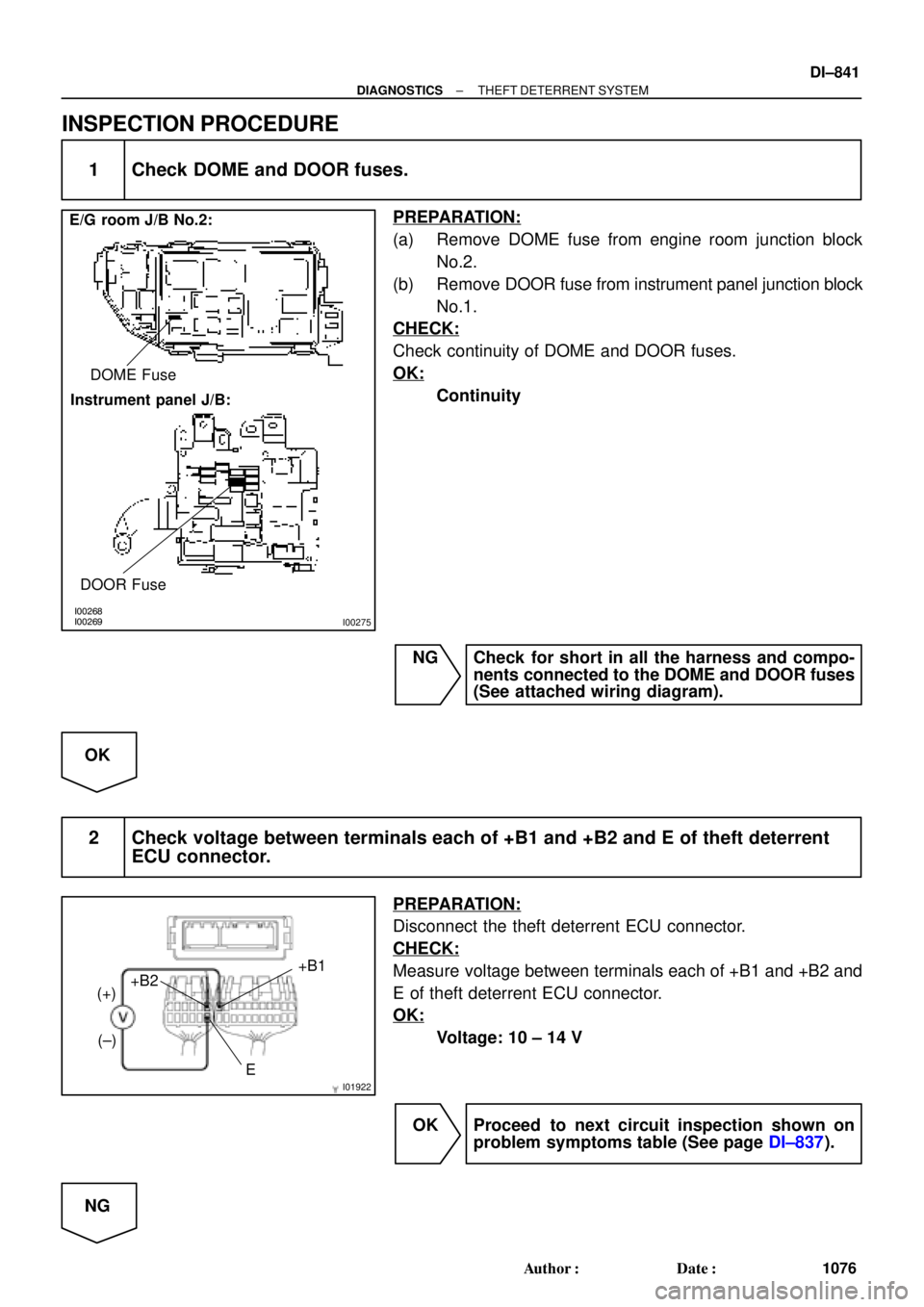
1 Check DOME and DOOR fuses.
PREPARATION:
(a) Remove DOME fuse from engine room junction block
No.2.
(b) Remove DOOR fuse from instrument panel junction block
No.1.
CHECK:
Check continuity of DOME and DOOR fuses.
OK:
Continuity
NG Check for short in all the harness and compo-
nents connected to the DOME and DOOR fuses
(See attached wiring diagram).
OK
2 Check voltage between terminals each of +B1 and +B2 and E of theft deterrent
ECU connector.
PREPARATION:
Disconnect the theft deterrent ECU connector.
CHECK:
Measure voltage between terminals each of +B1 and +B2 and
E of theft deterrent ECU connector.
OK:
Voltage: 10 ± 14 V
OK Proceed to next circuit inspection shown on
problem symptoms table (See page DI±837).
NG
Page 3272 of 4770
I00269
Instrument panel J/B:
ECU±IG Fuse
I01926
IG (+) (±)
DI±852
± DIAGNOSTICSTHEFT DETERRENT SYSTEM
1087 Author�: Date�:
INSPECTION PROCEDURE
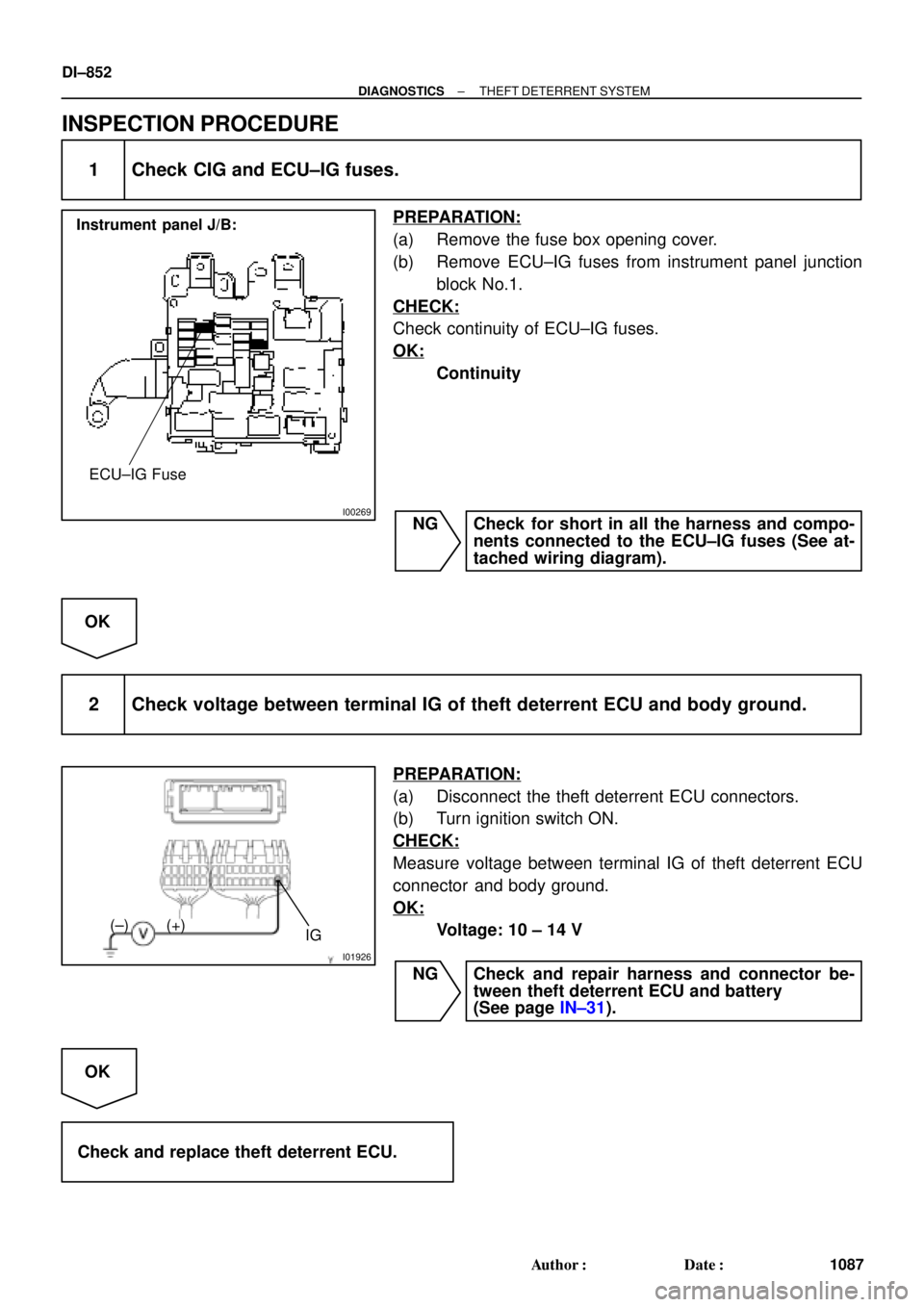
1 Check CIG and ECU±IG fuses.
PREPARATION:
(a) Remove the fuse box opening cover.
(b) Remove ECU±IG fuses from instrument panel junction
block No.1.
CHECK:
Check continuity of ECU±IG fuses.
OK:
Continuity
NG Check for short in all the harness and compo-
nents connected to the ECU±IG fuses (See at-
tached wiring diagram).
OK
2 Check voltage between terminal IG of theft deterrent ECU and body ground.
PREPARATION:
(a) Disconnect the theft deterrent ECU connectors.
(b) Turn ignition switch ON.
CHECK:
Measure voltage between terminal IG of theft deterrent ECU
connector and body ground.
OK:
Voltage: 10 ± 14 V
NG Check and repair harness and connector be-
tween theft deterrent ECU and battery
(See page IN±31).
OK
Check and replace theft deterrent ECU.
Page 3676 of 4770
BE1367
Medium Current Fuse and High Current Fuse
Equal Amperage Rating
V00076
Abbreviation Part Name Symbol Illustration
FUSE
MEDIUM CURRENT FUSE
HIGH CURRENT FUSE
FUSIBLE LINK
CIRCUIT BREAKERFUSE
M±FUSE
H±FUSE
FL
CB
± INTRODUCTIONREPAIR INSTRUCTIONS
IN±5
5 Author�: Date�:
(3) Precoated parts are indicated in the component il-
lustrations by the º�º symbol.
(g) When necessary, use a sealer on gaskets to prevent
leaks.
(h) Carefully observe all specifications for bolt tightening
torques. Always use a torque wrench.
(i) Use of special service tools (SST) and special service ma-
terials (SSM) may be required, depending on the nature
of the repair. Be sure to use SST and SSM where speci-
fied and follow the proper work procedure. A list of SST
and SSM can be found in Preparation section in this
manual.
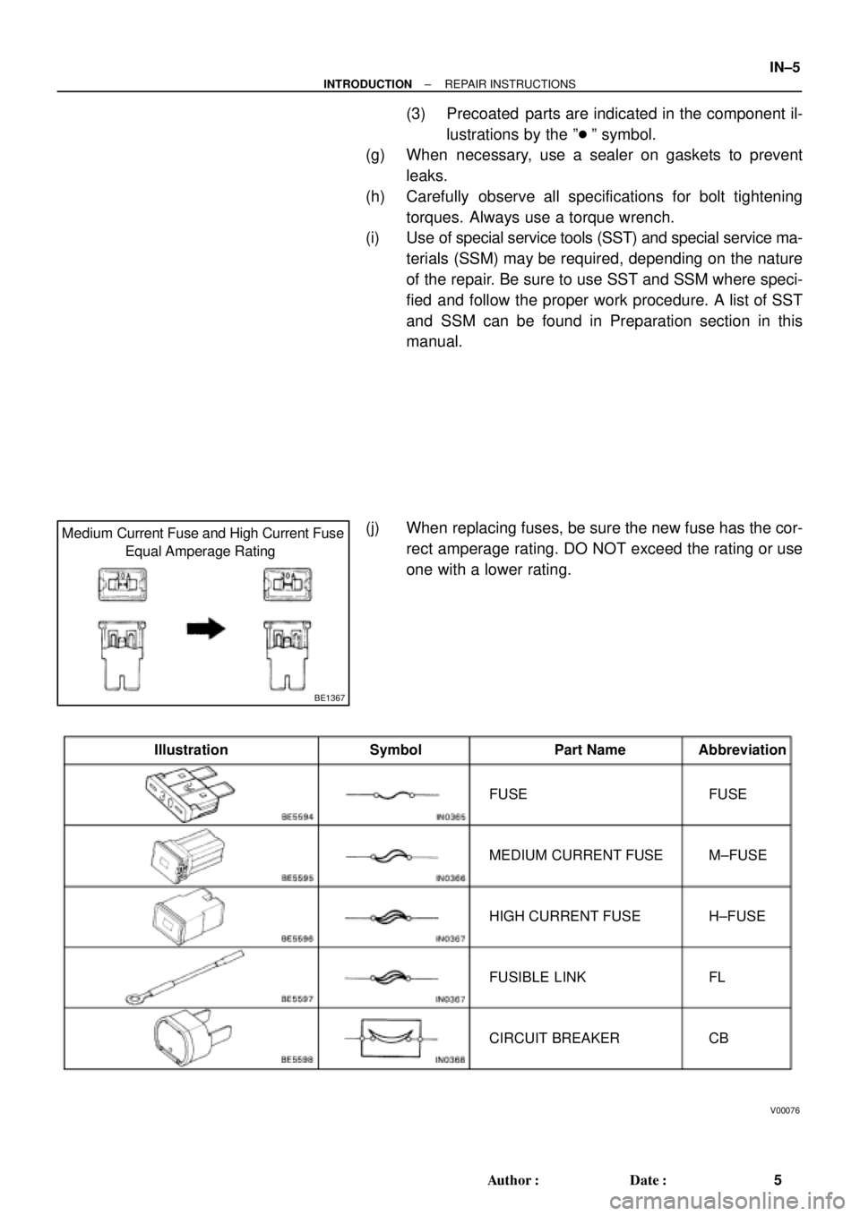
(j) When replacing fuses, be sure the new fuse has the cor-
rect amperage rating. DO NOT exceed the rating or use
one with a lower rating.
Page 4040 of 4770
S05331
SF0D7±03
S05327
Fuel Inlet Hose
S05522
SF±6
± SFI (5S±FE)FUEL PUMP
1439 Author�: Date�:
FUEL PUMP
ON±VEHICLE INSPECTION
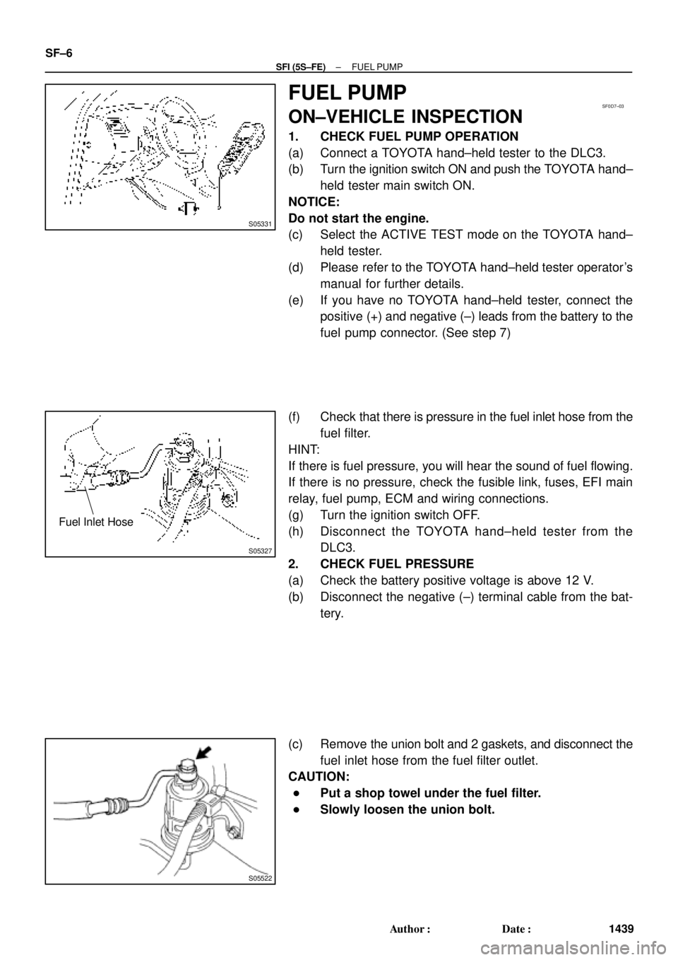
1. CHECK FUEL PUMP OPERATION
(a) Connect a TOYOTA hand±held tester to the DLC3.
(b) Turn the ignition switch ON and push the TOYOTA hand±
held tester main switch ON.
NOTICE:
Do not start the engine.
(c) Select the ACTIVE TEST mode on the TOYOTA hand±
held tester.
(d) Please refer to the TOYOTA hand±held tester operator's
manual for further details.
(e) If you have no TOYOTA hand±held tester, connect the
positive (+) and negative (±) leads from the battery to the
fuel pump connector. (See step 7)
(f) Check that there is pressure in the fuel inlet hose from the
fuel filter.
HINT:
If there is fuel pressure, you will hear the sound of fuel flowing.
If there is no pressure, check the fusible link, fuses, EFI main
relay, fuel pump, ECM and wiring connections.
(g) Turn the ignition switch OFF.
(h) Disconnect the TOYOTA hand±held tester from the
DLC3.
2. CHECK FUEL PRESSURE
(a) Check the battery positive voltage is above 12 V.
(b) Disconnect the negative (±) terminal cable from the bat-
tery.
(c) Remove the union bolt and 2 gaskets, and disconnect the
fuel inlet hose from the fuel filter outlet.
CAUTION:
�Put a shop towel under the fuel filter.
�Slowly loosen the union bolt.
Page 4106 of 4770
S05358
TOYOTA
Hand Held TesterSF079±04
S05353
S05359
Fuel Tube Connector
SF±6
± SFI (1MZ±FE)FUEL PUMP
1505 Author�: Date�:
FUEL PUMP
ON±VEHICLE INSPECTION
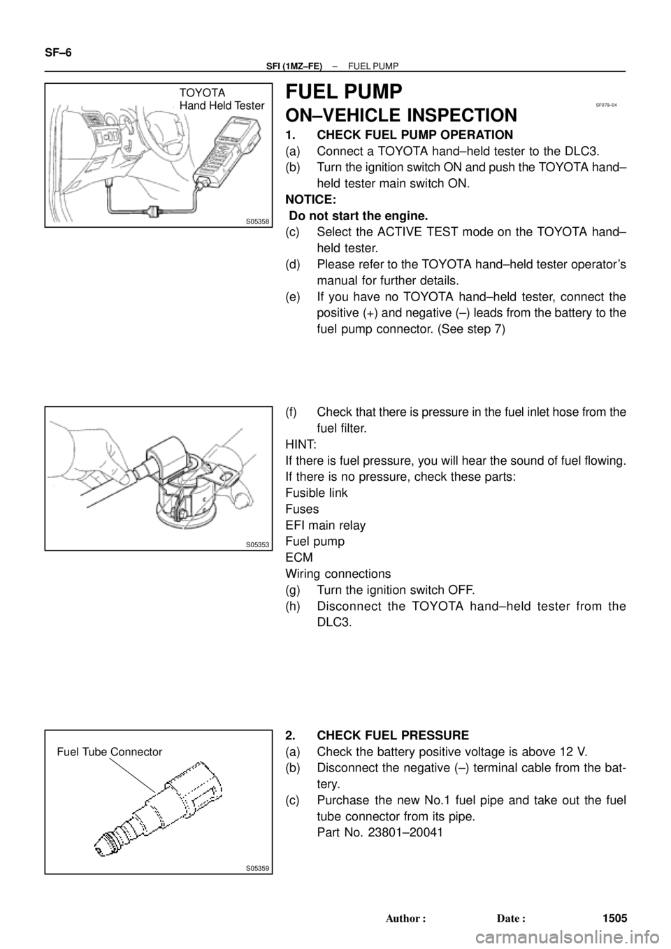
1. CHECK FUEL PUMP OPERATION
(a) Connect a TOYOTA hand±held tester to the DLC3.
(b) Turn the ignition switch ON and push the TOYOTA hand±
held tester main switch ON.
NOTICE:
Do not start the engine.
(c) Select the ACTIVE TEST mode on the TOYOTA hand±
held tester.
(d) Please refer to the TOYOTA hand±held tester operator's
manual for further details.
(e) If you have no TOYOTA hand±held tester, connect the
positive (+) and negative (±) leads from the battery to the
fuel pump connector. (See step 7)
(f) Check that there is pressure in the fuel inlet hose from the
fuel filter.
HINT:
If there is fuel pressure, you will hear the sound of fuel flowing.
If there is no pressure, check these parts:
Fusible link
Fuses
EFI main relay
Fuel pump
ECM
Wiring connections
(g) Turn the ignition switch OFF.
(h) Disconnect the TOYOTA hand±held tester from the
DLC3.
2. CHECK FUEL PRESSURE
(a) Check the battery positive voltage is above 12 V.
(b) Disconnect the negative (±) terminal cable from the bat-
tery.
(c) Purchase the new No.1 fuel pipe and take out the fuel
tube connector from its pipe.
Part No. 23801±20041