MX04D±01
Q09982
Q09999
BA
Q10000
Q10001
MX±4
± MANUAL TRANSAXLE (S51)MANUAL TRANSAXLE UNIT
1854 Author�: Date�:
REMOVAL
1. REMOVE HOOD
HINT:
At the time of installation, please refer to the following item.
Adjust the hood.
(See page BO±10)
2. REMOVE BATTERY AND AIR CLEANER CASE AS-
SEMBLY WITH AIR HOSE
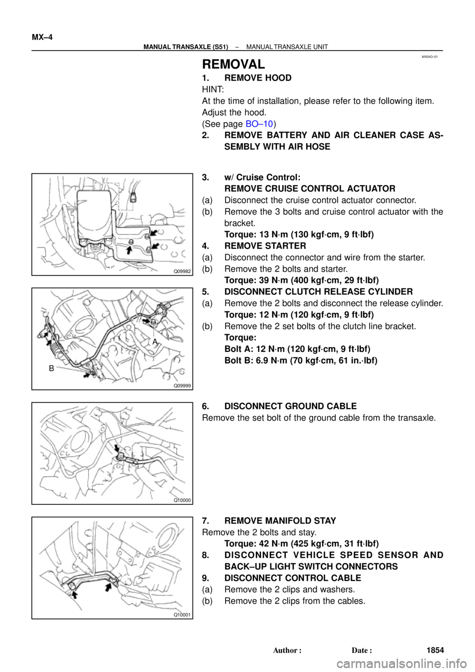
3. w/ Cruise Control:
REMOVE CRUISE CONTROL ACTUATOR
(a) Disconnect the cruise control actuator connector.
(b) Remove the 3 bolts and cruise control actuator with the
bracket.
Torque: 13 N´m (130 kgf´cm, 9 ft´lbf)
4. REMOVE STARTER
(a) Disconnect the connector and wire from the starter.
(b) Remove the 2 bolts and starter.
Torque: 39 N´m (400 kgf´cm, 29 ft´lbf)
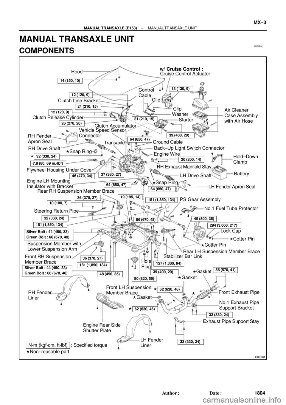
5. DISCONNECT CLUTCH RELEASE CYLINDER
(a) Remove the 2 bolts and disconnect the release cylinder.
Torque: 12 N´m (120 kgf´cm, 9 ft´lbf)
(b) Remove the 2 set bolts of the clutch line bracket.
Torque:
Bolt A: 12 N´m (120 kgf´cm, 9 ft´lbf)
Bolt B: 6.9 N´m (70 kgf´cm, 61 in.´lbf)
6. DISCONNECT GROUND CABLE
Remove the set bolt of the ground cable from the transaxle.
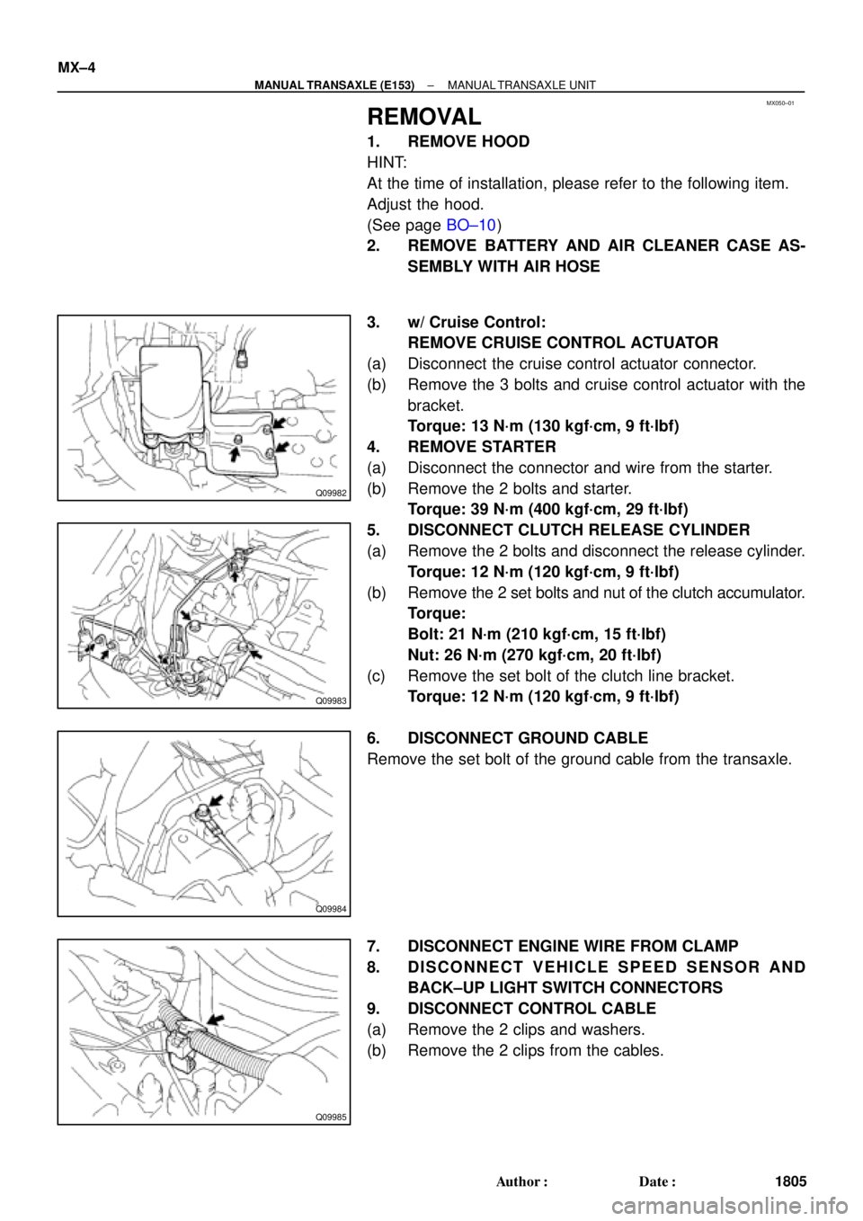
7. REMOVE MANIFOLD STAY
Remove the 2 bolts and stay.
Torque: 42 N´m (425 kgf´cm, 31 ft´lbf)
8. DISCONNECT VEHICLE SPEED SENSOR AND
BACK±UP LIGHT SWITCH CONNECTORS
9. DISCONNECT CONTROL CABLE
(a) Remove the 2 clips and washers.
(b) Remove the 2 clips from the cables.
MX04Z±01
Q09981
Hood
14 (150, 10)
w/ Cruise Control :
Cruise Control Actuator
12 (120, 9)
Clutch Line Bracket
21 (210, 15)
12 (120, 9)
Clutch Release Cylinder
26 (270, 20)
RH Drive Shaft�
�32 (330, 24)
7.8 (80, 69 in.´lbf)
Flywheel Housing Under CoverRH Fender
Apron SealClutch Accumulator
Vehicle Speed Sensor
Connector
46 (470, 34)
Engine LH Mounting
Insulator with Bracket
Rear RH Suspension Member Brace
37 (380, 27)
Transaxle
64 (650, 47)
36 (370, 27)
10 (100, 7)
Steering Return Pipe
19 (195, 14)
32 (330, 24)
181 (1,850, 134)
Silver Bolt : 44 (450, 33)
Green Bolt : 66 (670, 48)
Suspension Member with
Lower Suspension Arm
Front RH Suspension
Member Brace
181 (1,850, 134)
Control
Cable
Clip13 (130, 9)
Clip
Washer
Starter
21 (210, 15)
39 (400, 29)
Air Cleaner
Case Assembly
with Air Hose
64 (650, 47)Ground Cable
x5Back±Up Light Switch Connector
Engine Wire
20 (200, 14)Hold±Down
Clamp
Battery
LH Drive Shaft
LH Fender Apron Seal RH Exhaust Manifold Stay
64 (650, 47)
181 (1,850, 134)PS Gear Assembly
No.1 Fuel Tube Protector
49 (500, 36)
294 (3,000, 217)
Lock Cap
Rear LH Suspension Member Brace
Stabilizer Bar Link
Hole
Plug
127 (1,300, 94)
39 (400, 29)
80 (820, 59)48 (490, 35)
Silver Bolt : 44 (450, 33)
Green Bolt : 66 (670, 48)
Front LH Suspension
Member Brace RH Fender
Liner
Engine Rear Side
Shutter Plate
56 (570, 41)
�
�
62 (630, 46) �
62 (630, 46) �
Front Exhaust Pipe
No.1 Exhaust Pipe
Support Bracket
33 (330, 24)
Exhaust Pipe Support Stay
33 (330, 24)LH Fender
Liner
66 (670, 48)
Snap Ring
�Snap Ring
�Cotter Pin
�Cotter Pin
�Gasket
�Gasket
�Gasket
Non±reusable part: Specified torque
N´m (kgf´cm, ft´lbf)
�
36 (370, 27)
± MANUAL TRANSAXLE (E153)MANUAL TRANSAXLE UNIT
MX±3
1804 Author�: Date�:
MANUAL TRANSAXLE UNIT
COMPONENTS
MX050±01
Q09982
Q09983
Q09984
Q09985
MX±4
± MANUAL TRANSAXLE (E153)MANUAL TRANSAXLE UNIT
1805 Author�: Date�:
REMOVAL
1. REMOVE HOOD
HINT:
At the time of installation, please refer to the following item.
Adjust the hood.
(See page BO±10)
2. REMOVE BATTERY AND AIR CLEANER CASE AS-
SEMBLY WITH AIR HOSE
3. w/ Cruise Control:
REMOVE CRUISE CONTROL ACTUATOR
(a) Disconnect the cruise control actuator connector.
(b) Remove the 3 bolts and cruise control actuator with the
bracket.
Torque: 13 N´m (130 kgf´cm, 9 ft´lbf)
4. REMOVE STARTER
(a) Disconnect the connector and wire from the starter.
(b) Remove the 2 bolts and starter.
Torque: 39 N´m (400 kgf´cm, 29 ft´lbf)
5. DISCONNECT CLUTCH RELEASE CYLINDER
(a) Remove the 2 bolts and disconnect the release cylinder.
Torque: 12 N´m (120 kgf´cm, 9 ft´lbf)
(b) Remove the 2 set bolts and nut of the clutch accumulator.
Torque:
Bolt: 21 N´m (210 kgf´cm, 15 ft´lbf)
Nut: 26 N´m (270 kgf´cm, 20 ft´lbf)
(c) Remove the set bolt of the clutch line bracket.
Torque: 12 N´m (120 kgf´cm, 9 ft´lbf)
6. DISCONNECT GROUND CABLE
Remove the set bolt of the ground cable from the transaxle.
7. DISCONNECT ENGINE WIRE FROM CLAMP
8. DISCONNECT VEHICLE SPEED SENSOR AND
BACK±UP LIGHT SWITCH CONNECTORS
9. DISCONNECT CONTROL CABLE
(a) Remove the 2 clips and washers.
(b) Remove the 2 clips from the cables.