Page 2671 of 4770
± DIAGNOSTICSENGINE (1MZ±FE)
DI±251
486 Author�: Date�:
INSPECTION PROCEDURE
HINT:
Read freeze frame data using TOYOTA hand±held tester or OBD II scan tool. Because freeze frame records
the engine conditions when the malfunction is detected, when troubleshooting it is useful for determining
whether the vehicle was running or stopped, the engine warmed up or not, the air±fuel ratio lean or rich, etc.
at the time of the malfunction.
1 Are there any other codes (besides DTC P0125) being output ?
YES Go to relevant DTC chart.
NO
Page 2676 of 4770

P18349
DI±256
± DIAGNOSTICSENGINE (1MZ±FE)
491 Author�: Date�:
HINT:
If a malfunction exists, the MIL will light up during step (6).
NOTICE:
If the conditions in this test are not strictly followed, detection of the malfunction will not be possible.
If you do not have a TOYOTA hand±held tester, turn the ignition switch OFF after performing steps
(3) to (6), then perform steps (3) to (6) again.
INSPECTION PROCEDURE
HINT:
Read freeze frame data using TOYOTA hand±held tester or OBD II scan tool. Because freeze frame records
the engine conditions when the malfunction is detected, when troubleshooting it is useful for determining
whether the vehicle was running or stopped, the engine warmed up or not, the air±fuel ratio lean or rich, etc.
at the time of the malfunction.
1 Are there any other codes (besides DTC P0130, P0150) being output ?
YES Go to relevant DTC chart.
NO
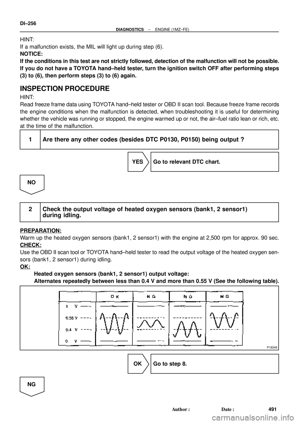
2 Check the output voltage of heated oxygen sensors (bank1, 2 sensor1)
during idling.
PREPARATION:
Warm up the heated oxygen sensors (bank1, 2 sensor1) with the engine at 2,500 rpm for approx. 90 sec.
CHECK:
Use the OBD II scan tool or TOYOTA hand±held tester to read the output voltage of the heated oxygen sen-
sors (bank1, 2 sensor1) during idling.
OK:
Heated oxygen sensors (bank1, 2 sensor1) output voltage:
Alternates repeatedly between less than 0.4 V and more than 0.55 V (See the following table).
OK Go to step 8.
NG
Page 2679 of 4770

± DIAGNOSTICSENGINE (1MZ±FE)
DI±259
494 Author�: Date�:
DTC P0133 Heated Oxygen Sensor Circuit Slow
Response (Bank 1 Sensor 1) (Ex. CA Spec.)
DTC P0153 Heated Oxygen Sensor Circuit Slow
Response (Bank 2 Sensor 1) (Ex. CA Spec.)
CIRCUIT DESCRIPTION
Refer to DTC P0125 (Insufficient Coolant Temp. for Closed Loop Fuel Control) on page DI±244.
DTC No.DTC Detecting ConditionTrouble Area
P0133
P0153
Response time for heated oxygen sensor's voltage output to
change from rich to lean, or from lean to rich, is 1 sec. or more
during idling after engine is warmed up
(2 trip detection logic)
�Heated oxygen sensor
�Fuel trim malfunction
HINT:
Bank 1 refers to the bank that includes cylinder No.1. Bank 2 refers to the bank that does not include cylinder
No.1. Sensor 1 refers to the sensor closer to the engine body.
INSPECTION PROCEDURE
HINT:
Read freeze frame data using TOYOTA hand±held tester or OBD II scan tool. Because freeze frame records
the engine conditions when the malfunction is detected, when troubleshooting it is useful for determining
whether the vehicle was running or stopped, the engine warmed up or not, the air±fuel ratio lean or rich, etc.
at the time of the malfunction.
1 Are there any other codes (besides DTC P0133, P0153) being output ?
YES Go to relevant DTC chart.
NO
DI4DQ±01
Page 2685 of 4770

± DIAGNOSTICSENGINE (1MZ±FE)
DI±265
500 Author�: Date�:
DTC P0136 Heated Oxygen Sensor Circuit Malfunction
(Bank 1 Sensor 2)
CIRCUIT DESCRIPTION
Refer to DTC P0125 (Insufficient Coolant Temp. for Closed Loop Fuel Control) on page DI±244.
DTC No.DTC Detecting ConditionTrouble Area
P0136
Voltage output of heated oxygen sensor (bank 1 sensor 2)
remains at 0.4 V or more or 0.6*1 0.5*2 V or less when vehicle
is driven at 50 km/h (31 mph) or more after engine is warmed
up
*
1: for California Spec.
*2: except California Spec.
(2 trip detection logic)
�Heated oxygen sensor
HINT:
Bank 1 refers to the bank that includes cylinder No.1. Sensor 2 refers to the sensor farther away from the
engine body.
WIRING DIAGRAM
Refer to DTC P0125 (Insufficient Coolant Temp. for Closed Loop Fuel Control) on page DI±244.
INSPECTION PROCEDURE
HINT:
Read freeze frame data using TOYOTA hand±held tester or OBD II scan tool. Because freeze frame records
the engine conditions when the malfunction is detected, when troubleshooting it is useful for determining
whether the vehicle was running or stopped, the engine warmed up or not, the air fuel ratio lean or rich, etc.
at the time of the malfunction.
1 Are there any other codes (besides DTC P0136) being output ?
YES Go to relevant DTC chart.
NO
2 Check for open and short in harness and connector between ECM and heated
oxygen sensor (See page IN±31).
NG Repair or replace harness or connector.
OK
DI07Q±06
Page 2697 of 4770

A03319
Instrument
Panel J/B
Engine
Room
J/B
N0.2
BatteryFL
MAINB±GB±R B±R
B±R
W±RJ18
Junction
Connector
B±R
B±R
B±R
B±R
B±R
B±R2
2
2
2
2
21
1
1
1
1
1L
R
Y
W
R±L
GE10
Ignition
Switch
No. 1
No. 2
No. 3
No. 4
No. 5
No. 6
Injector
BR
BR
EC
II3
5
6
21
311
2
3
4#10
#20
#30
#40
#50
#60
E01
E02ECM
12
2L
2A
AM2
4
1
B
F4F6 11 6
7
1K 1K 1C
1B 38
55
W±RE10
E11
E11
E11
E11
E11
E11 Fusible
Link
Block
± DIAGNOSTICSENGINE (1MZ±FE)
DI±277
512 Author�: Date�:
HINT:
When the 2 or more codes for a misfiring cylinder are recorded repeatedly but no Random Misfire code is
recorded, it indicates that the misfires were detected and recorded at different times.
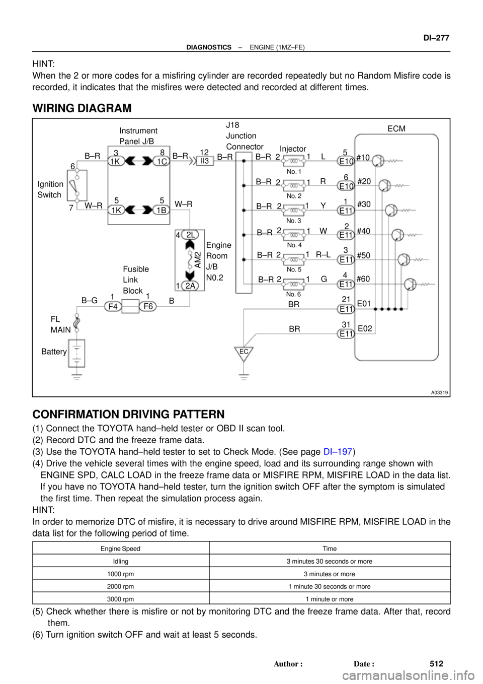
WIRING DIAGRAM
CONFIRMATION DRIVING PATTERN
(1) Connect the TOYOTA hand±held tester or OBD II scan tool.
(2) Record DTC and the freeze frame data.
(3) Use the TOYOTA hand±held tester to set to Check Mode. (See page DI±197)
(4) Drive the vehicle several times with the engine speed, load and its surrounding range shown with
ENGINE SPD, CALC LOAD in the freeze frame data or MISFIRE RPM, MISFIRE LOAD in the data list.
If you have no TOYOTA hand±held tester, turn the ignition switch OFF after the symptom is simulated
the first time. Then repeat the simulation process again.
HINT:
In order to memorize DTC of misfire, it is necessary to drive around MISFIRE RPM, MISFIRE LOAD in the
data list for the following period of time.
Engine SpeedTime
Idling3 minutes 30 seconds or more
1000 rpm3 minutes or more
2000 rpm1 minute 30 seconds or more
3000 rpm1 minute or more
(5) Check whether there is misfire or not by monitoring DTC and the freeze frame data. After that, record
them.
(6) Turn ignition switch OFF and wait at least 5 seconds.
Page 2726 of 4770

FI6514
OX Signal Waveform (Oscilloscope)
1 V
0 V
200 m sec./Division
DI±306
± DIAGNOSTICSENGINE (1MZ±FE)
541 Author�: Date�:
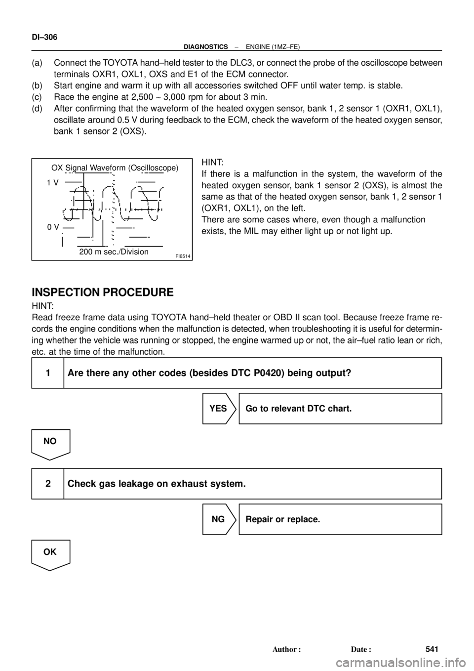
(a) Connect the TOYOTA hand±held tester to the DLC3, or connect the probe of the oscilloscope between
terminals OXR1, OXL1, OXS and E1 of the ECM connector.
(b) Start engine and warm it up with all accessories switched OFF until water temp. is stable.
(c) Race the engine at 2,500 ~ 3,000 rpm for about 3 min.
(d) After confirming that the waveform of the heated oxygen sensor, bank 1, 2 sensor 1 (OXR1, OXL1),
oscillate around 0.5 V during feedback to the ECM, check the waveform of the heated oxygen sensor,
bank 1 sensor 2 (OXS).
HINT:
If there is a malfunction in the system, the waveform of the
heated oxygen sensor, bank 1 sensor 2 (OXS), is almost the
same as that of the heated oxygen sensor, bank 1, 2 sensor 1
(OXR1, OXL1), on the left.
There are some cases where, even though a malfunction
exists, the MIL may either light up or not light up.
INSPECTION PROCEDURE
HINT:
Read freeze frame data using TOYOTA hand±held theater or OBD II scan tool. Because freeze frame re-
cords the engine conditions when the malfunction is detected, when troubleshooting it is useful for determin-
ing whether the vehicle was running or stopped, the engine warmed up or not, the air±fuel ratio lean or rich,
etc. at the time of the malfunction.
1 Are there any other codes (besides DTC P0420) being output?
YES Go to relevant DTC chart.
NO
2 Check gas leakage on exhaust system.
NG Repair or replace.
OK
Page 2729 of 4770

A00479
Engine Speed
3,000 rpm
2,000 rpm
Idling
IG SW OFF(a)
Warmed up3 min. or so
2 sec. 2 sec.
CheckTime (b)(c)
(d)
± DIAGNOSTICSENGINE (1MZ±FE)
DI±309
544 Author�: Date�:
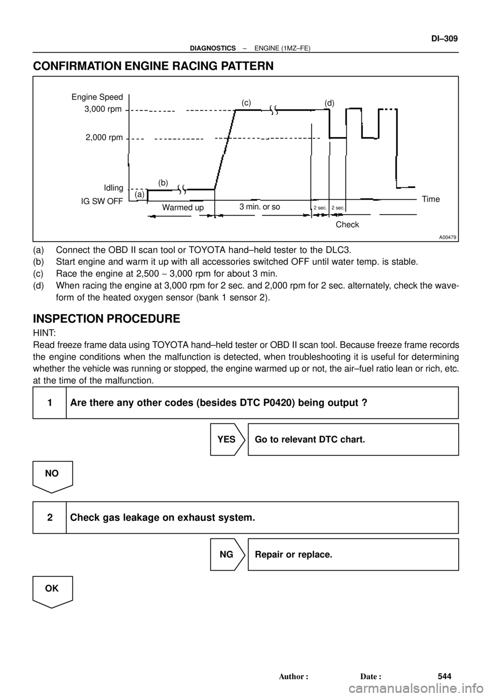
CONFIRMATION ENGINE RACING PATTERN
(a) Connect the OBD II scan tool or TOYOTA hand±held tester to the DLC3.
(b) Start engine and warm it up with all accessories switched OFF until water temp. is stable.
(c) Race the engine at 2,500 ~ 3,000 rpm for about 3 min.
(d) When racing the engine at 3,000 rpm for 2 sec. and 2,000 rpm for 2 sec. alternately, check the wave-
form of the heated oxygen sensor (bank 1 sensor 2).
INSPECTION PROCEDURE
HINT:
Read freeze frame data using TOYOTA hand±held tester or OBD II scan tool. Because freeze frame records
the engine conditions when the malfunction is detected, when troubleshooting it is useful for determining
whether the vehicle was running or stopped, the engine warmed up or not, the air±fuel ratio lean or rich, etc.
at the time of the malfunction.
1 Are there any other codes (besides DTC P0420) being output ?
YES Go to relevant DTC chart.
NO
2 Check gas leakage on exhaust system.
NG Repair or replace.
OK
Page 2761 of 4770

A00364
Vehicle Speed
60 ~ 120 km/h
(38 ~ 75 mph)
Idling
IG SW OFF
3 ~ 5 min.
Time
(1) (2)(3)(4)
± DIAGNOSTICSENGINE (1MZ±FE)
DI±341
576 Author�: Date�:
CONFIRMATION DRIVING PATTERN
(a) Connect the TOYOTA hand±held tester to the DLC3.
(b) Switch the TOYOTA hand±held tester from normal mode to check mode (See page DI±197).
(c) Start the engine and warm it up with all accessory switches OFF.
(d) Drive the vehicle at 60 ~ 120 km/h (38 ~ 75 mph) and engine speed at 1,600 ~ 3,200 rpm for 3 ~ 5 min.
HINT:
If a malfunction exists, the MIL will light up during step (4).
NOTICE:
If the conditions in this test are not strictly followed, detection of the malfunction will not be possible.
If you do not have a TOYOTA hand±held tester, turn the ignition switch OFF after performing steps
(3) and (4), then perform steps (3) and (4) again.
INSPECTION PROCEDURE
HINT:
�If DTC P1130 is displayed, check Bank 1 Sensor 1 circuit.
�If DTC P1150 is displayed, check Bank 2 Sensor 1 circuit.
�Read frame freeze data using TOYOTA hand±held tester or OBD II scan tool. Because freeze frame
records the engine conditions when the malfunction is detected, when troubleshooting it is useful for
determining whether the vehicle was running or stopped, the engine warmed up or not, the air±fuel
ratio lean or rich, etc. at the time of the malfunction.
1 Are there any other codes (besides DTC P1130, P1150) being output?
YES Go to relevant DTC chart.
NO