2000 TOYOTA CAMRY transmission
[x] Cancel search: transmissionPage 1143 of 4770

Maintenance Log.
. SUVs & Tacoma
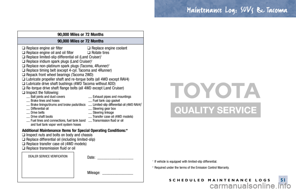
SCHEDULED MAINTENANCE LOGS51
90,000 Miles or 72 Months
❑Replace engine air filter❑Replace engine coolant❑Replace engine oil and oil filter❑Rotate tires❑Replace limited-slip differential oil (Land Cruiser)1
❑Replace iridium spark plugs (Land Cruiser)2
❑Replace non-platinum spark plugs (Tacoma, 4Runner)2
❑Replace timing belt (except 4-cyl. Tacoma and 4Runner)❑Repack front wheel bearings (Tacoma 2WD)❑Lubricate propeller shaft and re-torque bolts (all 4WD except RAV4)❑Lubricate drive shaft bushings (4WD Tacoma without ADD)❑Re-torque drive shaft flange bolts (all 4WD except Land Cruiser)❑Inspect the following:__
Ball joints and dust covers__
Exhaust pipes and mountings
__
Brake lines and hoses__
Fuel tank cap gasket
__
Brake linings/drums and brake pads/discs__
Limited-slip differential oil
(4WD RAV4)1
__
Differential oil__
Steering gear box
__
Drive belts__
Steering linkage
__
Drive shaft boots__
Transfer case oil (4WD models)
__
Fuel lines and connections, fuel tank band__
Transmission fluid or oil
and fuel tank vapor vent system hoses
Additional Maintenance Items for Special Operating Conditions:*❑Inspect nuts and bolts on body and chassis❑Replace differential oil (including limited-slip)❑Replace transfer case oil (4WD models)❑Replace transmission fluid or oil
Date: __________________
Mileage: _______________
90,000 Miles or 72 Months
90,000 Miles or 72 Months
DEALER SERVICE VERIFICATION1If vehicle is equipped with limited-slip differential.2Required under the terms of the Emission Control Warranty.
Page 1145 of 4770

Maintenance Log.
. SUVs & Tacoma
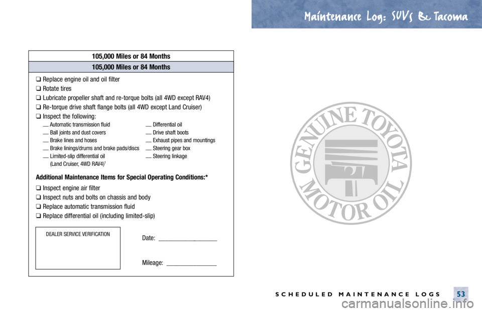
SCHEDULED MAINTENANCE LOGS53
105,000 Miles or 84 Months
❑Replace engine oil and oil filter
❑Rotate tires
❑Lubricate propeller shaft and re-torque bolts (all 4WD except RAV4)
❑Re-torque drive shaft flange bolts (all 4WD except Land Cruiser)
❑Inspect the following:__
Automatic transmission fluid__
Differential oil
__
Ball joints and dust covers__
Drive shaft boots
__
Brake lines and hoses__
Exhaust pipes and mountings
__
Brake linings/drums and brake pads/discs__
Steering gear box
__
Limited-slip differential oil__
Steering linkage
(Land Cruiser, 4WD RAV4)
1
Additional Maintenance Items for Special Operating Conditions:*
❑Inspect engine air filter
❑Inspect nuts and bolts on chassis and body
❑Replace automatic transmission fluid
❑Replace differential oil (including limited-slip)
Date: __________________
Mileage: _______________
105,000 Miles or 84 Months
105,000 Miles or 84 Months
DEALER SERVICE VERIFICATION
Page 1147 of 4770

Maintenance Log.
. SUVs & Tacoma
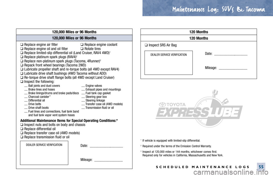
SCHEDULED MAINTENANCE LOGS55
120,000 Miles or 96 Months
❑Replace engine air filter❑Replace engine coolant❑Replace engine oil and oil filter❑Rotate tires❑Replace limited-slip differential oil (Land Cruiser, RAV4 4WD)1
❑Replace platinum spark plugs (RAV4)2
❑Replace non-platinum spark plugs (Tacoma, 4Runner)2
❑Repack front wheel bearings (Tacoma 2WD)❑Lubricate propeller shaft and re-torque bolts (all 4WD except RAV4)❑Lubricate drive shaft bushings (4WD Tacoma without ADD)❑Re-torque drive shaft flange bolts (all 4WD except Land Cruiser)❑Inspect the following:__
Ball joints and dust covers__
Engine valves
__
Brake lines and hoses__
Exhaust pipes and mountings
__
Brake linings/drums and brake pads/discs__
Fuel tank cap gasket
__
Charcoal canister
3__
Steering gear box
__
Differential oil__
Steering linkage
__
Drive belts__
Transfer case oil (4WD models)
__
Drive shaft boots__
Transmission fluid or oil
__
Fuel lines and connections, fuel tank band
and fuel tank vapor vent system hoses
Additional Maintenance Items for Special Operating Conditions:*❑Inspect nuts and bolts on body and chassis❑Replace differential oil❑Replace transfer case oil (4WD models)❑Replace transmission fluid or oil
Date: __________________
Mileage: _______________
120,000 Miles or 96 Months
120,000 Miles or 96 Months
120 Months
DEALER SERVICE VERIFICATION
120 Months
❑Inspect SRS Air Bag
Date: __________________
Mileage: _______________
DEALER SERVICE VERIFICATION
1If vehicle is equipped with limited-slip differential.2Required under the terms of the Emission Control Warranty.
3Inspect at 120,000 miles or 144 months, whichever comes first.
Required only for vehicles in California, Massachusetts and New York.
Page 1158 of 4770

B
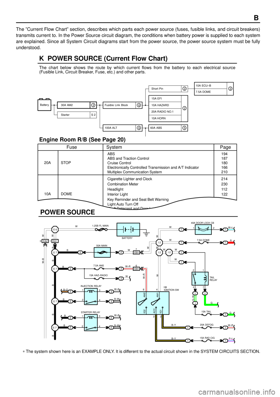
The ºCurrent Flow Chartº section, describes which parts each power source (fuses, fusible links, and circuit breakers)
transmits current to. In the Power Source circuit diagram, the conditions when battery power is supplied to each system
are explained. Since all System Circuit diagrams start from the power source, the power source system must be fully
understood.
Theft Deterrent and Door Lock Control
K POWER SOURCE (Current Flow Chart)
11
1
EA1 1EA2 3
7
EB16
E 6
E 7I 2I 2
I 2
E 7
E 7
E 7
2
1
1
2
2
2
2
2
B
B
W W
B B B B BW±B
B
B
B B±O
B±W
W±B
B±W STARTER RELAY INJECTION RELAY15A HAZ±RADIO7.5A AM250A MAIN 1.25B FL MAIN
BATTERY
WWW
W W W
R W±L
W
W
G±W
G
15A TAIL
20A DEFOG
15A RAD CIGTA I L
RELAY 7.5A DOME 40A DOOR LOCK CB
2 1
1 2
4 8
2 3
3 4
G
W±R
P±L B±Y
B±Y
W±R
AM2 IG2
ACC
IG1AM1W W
W±R
W W
W±B
21
1
1
1
1
2
2
2
2
3
4
3
4 1
2
1
22
1
11
1
IGNITION SW I 8
Battery
30A AM2
2
Starter S 220A RADIO NO.1
10A HORN
15A EFI
7.5A DOMEShort Pin
10A HAZARD
The chart below shows the route by which current flows from the battery to each electrical source
(Fusible Link, Circuit Breaker, Fuse, etc.) and other parts.
Engine Room R/B (See Page 20)
ABS
ABS and Traction Control
Cruise Control
Electronically Controlled Transmission and A/T Indicator
Multiplex Communication System
Cigarette Lighter and Clock
Key Reminder and Seat Belt Warning STOP
Fuse Page
194
214
11 2
System
DOME 20A
10ACombination Meter
Headlight
Interior Light
2
2
6 100A ALT
EB1
POWER SOURCE
Light Auto Turn Off187
180
166
210
230
122
10A ECU±B
5 60A ABS
2
6 Fusible Link Block2
* The system shown here is an EXAMPLE ONLY. It is different to the actual circuit shown in the SYSTEM CIRCUITS SECTION.
Page 1175 of 4770
![TOYOTA CAMRY 2000 Service Repair Manual G ELECTRICAL WIRING ROUTING
Position of Parts in Engine Compartment
[1MZ±FE]
A 1 A/C Condenser Fan Motor
A 2 A/C Magnetic Clutch and Lock Sensor
A 3 A/C Triple Pressure SW
(A/C Dual and Single Press TOYOTA CAMRY 2000 Service Repair Manual G ELECTRICAL WIRING ROUTING
Position of Parts in Engine Compartment
[1MZ±FE]
A 1 A/C Condenser Fan Motor
A 2 A/C Magnetic Clutch and Lock Sensor
A 3 A/C Triple Pressure SW
(A/C Dual and Single Press](/manual-img/14/57447/w960_57447-1174.png)
G ELECTRICAL WIRING ROUTING
Position of Parts in Engine Compartment
[1MZ±FE]
A 1 A/C Condenser Fan Motor
A 2 A/C Magnetic Clutch and Lock Sensor
A 3 A/C Triple Pressure SW
(A/C Dual and Single Pressure SW)
A 4 ABS Actuator
A 5 ABS Actuator
A 6 ABS Actuator and ECU
A 7 ABS and Traction Actuator
A 8 ABS and Traction Actuator
A 9 ABS Speed Sensor Front LH
A 10 ABS Speed Sensor Front RH
A 28 Air Fuel Ratio Sensor (Bank 1 Sensor 1)
A 29 Air Fuel Ratio Sensor (Bank 2 Sensor 1)
A 30 A/C Ambient Temp. Sensor
A 31 Airbag Sensor Front LH
A 32 Airbag Sensor Front RH
B 1 Back±Up Light SW
B 2 Brake Fluid Level Warning SW
C 1 Camshaft Position Sensor
C 2 Crankshaft Position Sensor
C 3 Cruise Control Actuator
D 1 Data Link Connector 1
D 2 Daytime Running Light Resistor
D 3 Diode (A/C)E 1 EGR Gas Temp. Sensor
E 2 EGR Valve Position Sensor
E 3 Electronically Controlled Transmission Solenoid
E 5 Engine Coolant Temp. Sensor
E 6 Engine Hood Courtesy SW
F 1 Front Turn Signal Light and Parking Light LH
F 2 Front Turn Signal Light and Parking Light RH
F 3 Front Wiper Motor
F 4 Fusible Link Block
F 5 Fusible Link Block
F 6 Fusible Link Block
F 7 Fusible Link Block
F 8 Fusible Link Block
F 9 Fusible Link Block
G 1 Generator
G 2 Generator
H 1 Headlight LH
H 2 Headlight RH
H 3 Heated Oxygen Sensor (Bank 1 Sensor 1)
H 4 Heated Oxygen Sensor (Bank 2 Sensor 1)
H 5 Horn (High)
H 6 Horn (Low)
Page 1176 of 4770
![TOYOTA CAMRY 2000 Service Repair Manual G
Position of Parts in Engine Compartment
[1MZ±FE]
I 1 Idle Air Control Valve
I 2 Igniter
I 5 Ignition Coil No.1
I 6 Ignition Coil No.2
I 7 Ignition Coil No.3
I 8 Injector No.1
I 9 Injector No.2
I 10 TOYOTA CAMRY 2000 Service Repair Manual G
Position of Parts in Engine Compartment
[1MZ±FE]
I 1 Idle Air Control Valve
I 2 Igniter
I 5 Ignition Coil No.1
I 6 Ignition Coil No.2
I 7 Ignition Coil No.3
I 8 Injector No.1
I 9 Injector No.2
I 10](/manual-img/14/57447/w960_57447-1175.png)
G
Position of Parts in Engine Compartment
[1MZ±FE]
I 1 Idle Air Control Valve
I 2 Igniter
I 5 Ignition Coil No.1
I 6 Ignition Coil No.2
I 7 Ignition Coil No.3
I 8 Injector No.1
I 9 Injector No.2
I 10 Injector No.3
I 11 Injector No.4
I 12 Injector No.5
I 13 Injector No.6
K 1 Knock Sensor 1
K 2 Knock Sensor 2
M 2 Mass Air Flow Meter
N 1 Noise Filter (Ignition)
O 1 Oil Pressure SW
P 1 Park/Neutral Position SW,A/T Indicator Light SW and
Back±Up Light SW
P 2 Power Steering Oil Pressure SWR 1 Radiator Fan Motor
S 1 Starter
S 2 Starter
T 1 Theft Deterrent Horn
T 2 Throttle Position Sensor
V 2 Vehicle Speed Sensor (Combination Meter)
V 3 Vehicle Speed Sensor
(Electronically Controlled Transmission)
V 4 VSV (EGR)
V 5 VSV (EVAP)
V 6 VSV (Intake Air Control)
W 1 Washer Level Warning SW
W 2 Washer Motor
W 3 Water Temp. Sender
W 4 Water Temp. SW No.1
W 5 Water Temp. SW No.2
Page 1177 of 4770
![TOYOTA CAMRY 2000 Service Repair Manual G ELECTRICAL WIRING ROUTING
Position of Parts in Engine Compartment
[5S±FE]
A 1 A/C Condenser Fan Motor
A 2 A/C Magnetic Clutch and Lock Sensor
A 3 A/C Triple Pressure SW
(A/C Dual and Single Pressu TOYOTA CAMRY 2000 Service Repair Manual G ELECTRICAL WIRING ROUTING
Position of Parts in Engine Compartment
[5S±FE]
A 1 A/C Condenser Fan Motor
A 2 A/C Magnetic Clutch and Lock Sensor
A 3 A/C Triple Pressure SW
(A/C Dual and Single Pressu](/manual-img/14/57447/w960_57447-1176.png)
G ELECTRICAL WIRING ROUTING
Position of Parts in Engine Compartment
[5S±FE]
A 1 A/C Condenser Fan Motor
A 2 A/C Magnetic Clutch and Lock Sensor
A 3 A/C Triple Pressure SW
(A/C Dual and Single Pressure SW)
A 4 ABS Actuator
A 5 ABS Actuator
A 6 ABS Actuator and ECU
A 9 ABS Speed Sensor Front LH
A 10 ABS Speed Sensor Front RH
A 11 Air Fuel Ratio Sensor
A 31 Airbag Sensor Front LH
A 32 Airbag Sensor Front RH
B 1 Back±Up Light SW
B 2 Brake Fluid Level Warning SW
C 1 Camshaft Position Sensor
C 2 Crankshaft Position Sensor
C 3 Cruise Control Actuator
D 1 Data Link Connector 1
D 2 Daytime Running Light ResistorE 3 Electronically Controlled Transmission Solenoid
E 4 Electronically Controlled Transmission Solenoid
E 5 Engine Coolant Temp. Sensor
E 6 Engine Hood Courtesy SW
F 1 Front Turn Signal Light and Parking Light LH
F 2 Front Turn Signal Light and Parking Light RH
F 3 Front Wiper Motor
F 4 Fusible Link Block
F 5 Fusible Link Block
F 6 Fusible Link Block
F 7 Fusible Link Block
F 8 Fusible Link Block
F 9 Fusible Link Block
G 1 Generator
G 2 Generator
H 1 Headlight LH
H 2 Headlight RH
H 3 Heated Oxygen Sensor (Bank 1 Sensor 1)
H 5 Horn (High)
H 6 Horn (Low)
Page 1220 of 4770

This system utilizes an engine control module and maintains overall control of the engine, transmission and so on. An outline
of the engine control is explained here.
1. INPUT SIGNALS
(1) Engine coolant temp. signal circuit
The engine coolant temp. sensor detects the engine coolant temp. and has a built±in thermistor with a resistance which
varies according to the water temp. is input into TERMINAL THW of the engine control module as a control signal.
(2) Intake air temp. signal circuit
The intake air temp. sensor is installed in the mass air flow meter and detects the intake air temp., which is input as a
control signal into TERMINAL THA of the engine control module.
(3) Oxygen sensor signal circuit
The oxygen density in the exhaust gases is detected and input as a control signal into TERMINALS OXL1, OXR1
(Except California) and OXS of the engine control module. To maintain stable detection performance by the heated
oxygen sensor, a heater is used for warming the sensor. The heater is also controlled by the engine control module
(HTL, HTR (Except California) and HTS).
(4) RPM signal circuit
Camshaft position and crankshaft position are detected by the camshaft position sensor and crankshaft position sensor.
The camshaft position is input as a control signal to TERMINAL G22+ of the engine control module, and the engine
RPM is input into TERMINAL NE+.
(5) Throttle signal circuit
The throttle position sensor detects the throttle valve opening angle as a control signal, which is input into TERMINAL
VTA1 of the engine control module.
(6) Vehicle speed signal circuit
The vehicle speed sensor, installed inside the transmission, detects the vehicle speed and inputs a control signal into
TERMINAL SPD of the engine control module.
(7) Park/Neutral position SW signal circuit
The Park/Neutral position SW detects whether the shift position is in neutral, parking or not, and inputs a control signal
into TERMINAL STA of the engine control module.
(8) A/C SW signal circuit
The A/C control assembly (Automatic A/C) or A/C Amplifier (Manual A/C) inputs the A/C operations into TERMINAL A/C
of the engine control module as a control signal.
(9) Battery signal circuit
(California or w/ engine immobiliser and/or traction control)
Voltage is always supplies to TERMINAL BATT of the engine control module.
If you turn on the ignition SW, the current goes from TERMINAL MREL of the engine control module to the EFI relay and
put on the relay, and the voltage related to the engine control module operation is supplied to TERMINAL +B of the
engine control module through the EFI relay.
(Except California or w/ engine immobiliser and/or traction control)
Voltage is constantly applied to TERMINAL BATT of the engine control module. When the ignition SW is turned on,
voltage for engine control module start±up power supply is applied to TERMINAL +B of engine control module via EFI
relay.
(10) Intake air volume signal circuit
Intake air volume is detected by the mass air flow meter and a signal is input into TERMINAL VG of the engine control
module as a control signal.
(11) NSW signal circuit
To confirm whether the engine is cranking, the voltage applied to the starter motor during cranking is detected and the
signal is input into TERMINAL NSW of the engine control module as a control signal.
(12) Engine knock signal circuit
Engine knocking is detected by the knock sensor 1 and 2, then the signals are input into TERMINALS KNKR and KNKL
of the engine control module as a control signal.
(13) Air fuel ratio signal circuit (California)
The air fuel ratio is detected and input as a control signal into TERMINALS AFL+, AFR+ of the engine control module.
SYSTEM OUTLINE