2000 SUZUKI SWIFT ring
[x] Cancel search: ringPage 58 of 447

7B-16 AUTOMATIC TRANSMISSION (4 A/T)
2. DIAGNOSTIC TROUBLE CODE (DTC) CHECK, RECORD AND CLEARANCE
To check DTC, refer to “DTC CHECK” in this section. When a DTC exists, it means existence of a malfunction in
the system represented by that code but whether it still exists (current) or it occurred in the past and has gone
(history) is unknown. To know it, clear this DTC once (Refer to “DTC CLEARANCE” in this section.), perform
test drive and/or “TROUBLE SYMPTOM CONFIRMATION” in this section and then check DTC again as
described in “DTC CHECK”. Attempt to diagnose the trouble based on the DTC recorded in this step only or fail-
ure to clear the DTC in this step may mislead the diagnosis or make diagnosing difficult. Even after checking the
DTC with the SUZUKI scan tool, diagnosis should be performed according to this flow chart to check TCM for
proper self-diagnosis function.
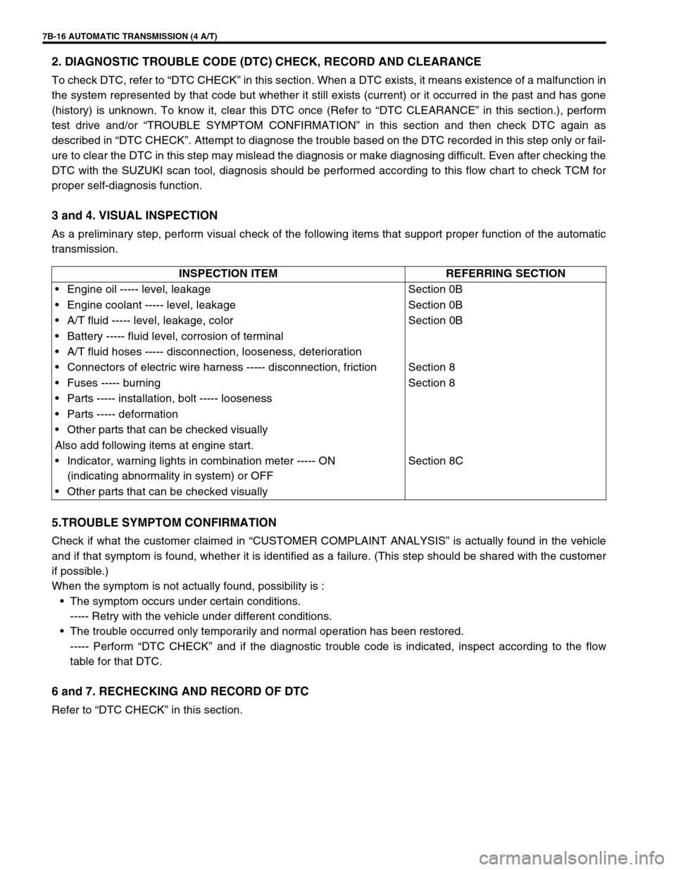
3 and 4. VISUAL INSPECTION
As a preliminary step, perform visual check of the following items that support proper function of the automatic
transmission.
5.TROUBLE SYMPTOM CONFIRMATION
Check if what the customer claimed in “CUSTOMER COMPLAINT ANALYSIS” is actually found in the vehicle
and if that symptom is found, whether it is identified as a failure. (This step should be shared with the customer
if possible.)
When the symptom is not actually found, possibility is :
The symptom occurs under certain conditions.
----- Retry with the vehicle under different conditions.
The trouble occurred only temporarily and normal operation has been restored.
----- Perform “DTC CHECK” and if the diagnostic trouble code is indicated, inspect according to the flow
table for that DTC.
6 and 7. RECHECKING AND RECORD OF DTC
Refer to “DTC CHECK” in this section.INSPECTION ITEM REFERRING SECTION
Engine oil ----- level, leakage Section 0B
Engine coolant ----- level, leakage Section 0B
A/T fluid ----- level, leakage, color Section 0B
Battery ----- fluid level, corrosion of terminal
A/T fluid hoses ----- disconnection, looseness, deterioration
Connectors of electric wire harness ----- disconnection, friction Section 8
Fuses ----- burning Section 8
Parts ----- installation, bolt ----- looseness
Parts ----- deformation
Other parts that can be checked visually
Also add following items at engine start.
Indicator, warning lights in combination meter ----- ON
(indicating abnormality in system) or OFFSection 8C
Other parts that can be checked visually
Page 59 of 447

AUTOMATIC TRANSMISSION (4 A/T) 7B-17
8. AUTOMATIC TRANSMISSION BASIC CHECK AND TROUBLE DIAGNOSIS TABLE
Perform basic automatic transmission check according to the list below first. When the end of the list has been
reached, check the part of system suspected as a possible cause referring to “TROUBLE DIAGNOSIS TABLE”
and based on symptoms appearing on vehicle (symptoms obtained through steps of customer complaint analy-
sis, trouble symptom confirmation and/or A/T basic check) and repair or replace faulty parts, if any.
AUTOMATIC TRANSMISSION BASIC CHECK LIST
1) Power Supply Voltage Check
Check that the battery voltage is within 10 – 14 V at engine stop.
2) A/T Fluid Check
Check A/T fluid level and quality.
3) STALL TEST
Perform stall test. Refer to “STALL TEST” in this section for details.
4) LINE PRESSURE TEST
Perform line pressure test. Refer to “LINE PRESSURE TEST” in this section.
5) ROAD TEST
Perform road test to understand correctly the trouble area.
6) Electrical Harness and Coupler Check
Check the connection of the harness coupler. Check for the loose connection of the harness, loose connec-
tion of the terminals.
9. DIAGNOSTIC TROUBLE CODE FLOW TABLE
Based on the DTC indicated in STEP 6 and STEP 7 and referring to “DTC CHECK”, locate the cause of the
trouble, namely in a sensor, switch, wire harness, connector, actuator, TCM or other part and repair or replace
faulty parts.
10. CHECK FOR INTERMITTENT PROBLEM
Check parts where an intermittent trouble is easy to occur (e.g. wire harness, connector, etc.), referring to
“INTERMITTENT AND POOR CONNECTION” in Section 0A and related circuit of DTC recorded in Step 2.
11. FINAL CONFIRMATION TEST
Confirm that the problem symptom has gone and the automatic transmission is free from any abnormal condi-
tions. If what has been repaired is related to the malfunction DTC, clear the DTC once and perform test driving
and confirm that a normal code is indicated.
Page 62 of 447

7B-20 AUTOMATIC TRANSMISSION (4 A/T)
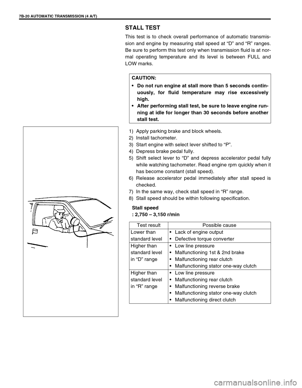
STALL TEST
This test is to check overall performance of automatic transmis-
sion and engine by measuring stall speed at “D” and “R” ranges.
Be sure to perform this test only when transmission fluid is at nor-
mal operating temperature and its level is between FULL and
LOW marks.
1) Apply parking brake and block wheels.
2) Install tachometer.
3) Start engine with select lever shifted to “P”.
4) Depress brake pedal fully.
5) Shift select lever to “D” and depress accelerator pedal fully
while watching tachometer. Read engine rpm quickly when it
has become constant (stall speed).
6) Release accelerator pedal immediately after stall speed is
checked.
7) In the same way, check stall speed in “R” range.
8) Stall speed should be within following specification.
Stall speed
: 2,750 – 3,150 r/min CAUTION:
Do not run engine at stall more than 5 seconds contin-
uously, for fluid temperature may rise excessively
high.
After performing stall test, be sure to leave engine run-
ning at idle for longer than 30 seconds before another
stall test.
Test result Possible cause
Lower than
standard levelLack of engine output
Defective torque converter
Higher than
standard level
in “D” rangeLow line pressure
Malfunctioning 1st & 2nd brake
Malfunctioning rear clutch
Malfunctioning stator one-way clutch
Higher than
standard level
in “R” rangeLow line pressure
Malfunctioning rear clutch
Malfunctioning reverse brake
Malfunctioning stator one-way clutch
Malfunctioning direct clutch
Page 64 of 447

7B-22 AUTOMATIC TRANSMISSION (4 A/T)
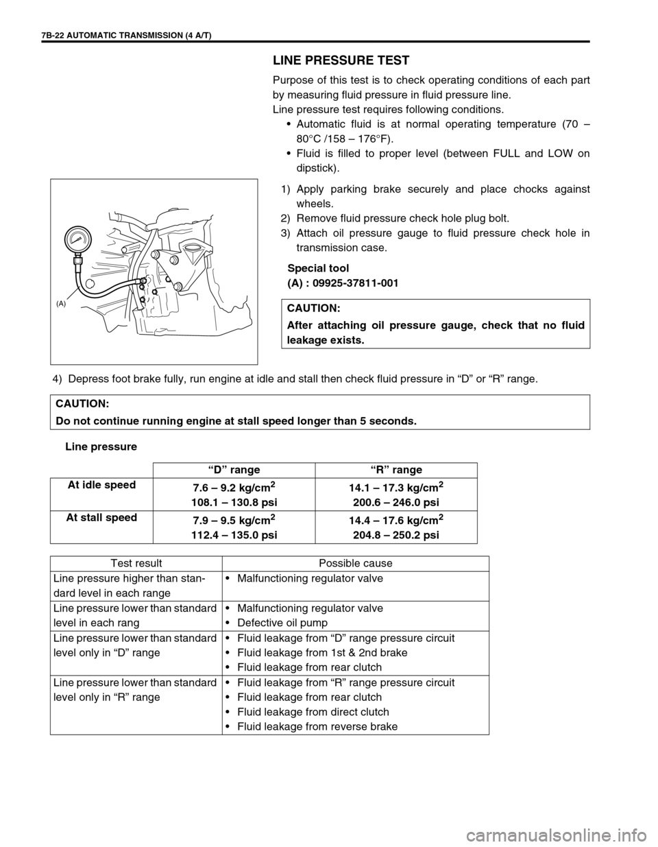
LINE PRESSURE TEST
Purpose of this test is to check operating conditions of each part
by measuring fluid pressure in fluid pressure line.
Line pressure test requires following conditions.
Automatic fluid is at normal operating temperature (70 –
80°C /158 – 176°F).
Fluid is filled to proper level (between FULL and LOW on
dipstick).
1) Apply parking brake securely and place chocks against
wheels.
2) Remove fluid pressure check hole plug bolt.
3) Attach oil pressure gauge to fluid pressure check hole in
transmission case.
Special tool
(A) : 09925-37811-001
4) Depress foot brake fully, run engine at idle and stall then check fluid pressure in “D” or “R” range.
Line pressureCAUTION:
After attaching oil pressure gauge, check that no fluid
leakage exists.
(A)
CAUTION:
Do not continue running engine at stall speed longer than 5 seconds.
“D” range “R” range
At idle speed
7.6 – 9.2 kg/cm
2
108.1 – 130.8 psi14.1 – 17.3 kg/cm
2
200.6 – 246.0 psi
At stall speed
7.9 – 9.5 kg/cm
2
112.4 – 135.0 psi14.4 – 17.6 kg/cm
2
204.8 – 250.2 psi
Test result Possible cause
Line pressure higher than stan-
dard level in each rangeMalfunctioning regulator valve
Line pressure lower than standard
level in each rangMalfunctioning regulator valve
Defective oil pump
Line pressure lower than standard
level only in “D” rangeFluid leakage from “D” range pressure circuit
Fluid leakage from 1st & 2nd brake
Fluid leakage from rear clutch
Line pressure lower than standard
level only in “R” rangeFluid leakage from “R” range pressure circuit
Fluid leakage from rear clutch
Fluid leakage from direct clutch
Fluid leakage from reverse brake
Page 65 of 447

AUTOMATIC TRANSMISSION (4 A/T) 7B-23
ENGINE BRAKE TEST
1) While driving vehicle in 3rd gear of “D” range, shift select lever down to “2” range and check if engine brake
operates.
2) In the same way as in Step 1), check engine brake for operation when select lever is shifted down to “L”
range.
3) Engine brake should operate in above test.
“P” RANGE TEST
1) Stop vehicle on a slope, shift select lever to “P” range and at the same time apply parking brake.
2) After stopping engine, depress brake pedal and release parking brake.
3) Then, release brake pedal gradually and check that vehicle remains stationary.
4) Depress brake pedal and shift select lever to “N” range.
5) Then, release brake pedal gradually and check that vehicle moves.WARNING:
Before test, make sure that there is no vehicle behind so as to pre-
vent rear-end collision.
Test result Possible cause
Fails to operate when shifted down to “2”
rangeDefective shift switch
1st & 2nd brake defective
Direct clutch defective
Fails to operate when shifted down to “L”
range
WARNING:
Before test, check to make sure no one is around vehicle or
down on a slope and keep watchful for safety during test.
Test result Possible cause
Vehicle moves at “P” range or
remains stationary at “N” rangeDefective parking lock pawl or
spring
Page 66 of 447

7B-24 AUTOMATIC TRANSMISSION (4 A/T)
ELECTRONIC CONTROL SYSTEM DIAGNO-
SIS
TCM has on-board diagnostic system (a system self-diagnosis
function). Investigate where the trouble is by referring to “DIAG-
NOSTIC FLOW TABLE” and “DTC TABLE” in this section.
PRECAUTIONS IN DIAGNOSING TROUBLES
[PRECAUTIONS IN IDENTIFYING DTC]
For vehicle equipped with immobilizer indicator lamp (2)
(which comes on when turning on ignition switch leaving
engine OFF), malfunction indicator lamp (MIL) (1) comes on
when TCM detects malfunction of automatic transmission
system.
For vehicle equipped without immobilizer indicator lamp (2),
malfunction indicator lamp (MIL) (1) does not come on
although TCM detects malfunction of automatic transmission
system.
Don’t disconnect couplers from TCM, battery cable from bat-
tery, TCM ground wire harness from engine or main fuse
before checking DTC stored in TCM memory.
Such disconnection will clear memorized information in TCM
memory.
Using SUZUKI scan tool (Tech-1) (4), diagnostic trouble
code (DTC) stored in TCM memory can be checked and
cleared as well.
Before its use, be sure to read Operator’s (instruction) Man-
ual supplied with it carefully to have good understanding of
its functions and usage.
Not using scan tool, the DTC stored in TCM memory also
can be checked and cleared.
DTC stored in the TCM memory is outputted by flashing of
“O/D OFF” lamp (3) with diagnosis switch terminal of monitor
connector No.2 (5) grounded.
If no DTC is stored in TCM memory, DTC No.12 is outputted
repeatedly.
If one or more DTCs are stored in TCM memory, they are
outputted starting from smallest code number in increasing
order.
After all DTCs are outputted, all DTCs are outputted repeat-
edly.
Be sure to read “PRECAUTIONS FOR ELECTRICAL CIR-
CUIT SERVICE” in Section 0A before inspection and
observe what is written there.
When replacing TCM with used one, all learned contents
which are stored in TCM memory should be erased after the
replacement referring to “LEARNING CONTROL INITIAL-
IZATION” in this section.
Page 76 of 447

7B-34 AUTOMATIC TRANSMISSION (4 A/T)
Figure for Step 1
Figure for Step 2
Figure for Step 33 Check input shaft speed sensor and out-
put shaft speed sensor referring to each
item in this section.
Are they OK?
(See figure.)Broken wire in shield portion
or broken “BLK” wire, or
shorted to power source cir-
cuit.
Malfunction of A/T itself (over
revolving of C0 clutch drum by
departing of C0 clutch drum
snap ring, clutch slipping, etc.)
If all the above are in good con-
dition, substitute a known-good
TCM and recheck.Inspect and replace
referring to each item in
this section. Step Action Yes No
1. Output shaft speed sensor
2. Input shaft speed sensor
Page 79 of 447

AUTOMATIC TRANSMISSION (4 A/T) 7B-37
DTC P0741 (DTC NO.29) TCC (LOCK-UP) SOLENOID PERFORMANCE OR STUCK OFF
Step Action Yes No
1Was “AUTOMATIC TRANSMISSION DIAG-
NOSTIC FLOW TABLE” performed?Go to Step 2. Go to “AUTOMATIC
TRANSMISSION DIAG-
NOSTIC FLOW TABLE”.
2 Check TCC (lock-up) solenoid referring to
“SHIFT SOLENOID VALVES” in this section.
Is it in good condition?Go to Step 3. Replace TCC (lock-up)
solenoid.
3 Check valve body for fluid passage clog, or
lock-up control valve, secondary regulator valve
or signal valve stuck, referring to “TRANSMIS-
SION UNIT REPAIR OVERHAUL” in this sec-
tion.
Are they in good condition?Go to Step 4. Faulty valve body.
4 Substitute a known-good torque converter and
recheck.
Is it OK?Torque converter mal-
function.Overhaul and repair auto-
matic transmission.
DTC DETECTING CONDITION
Difference between turbine rev. and engine rev. too close even though TCM ordered to turn OFF lock-up.
Difference between turbine rev. and engine rev. too wide even though TCM ordered to turn ON lock-up.