Page 21 of 447

MANUAL TRANSMISSION 7A-21
SUB ASSEMBLY SERVICE
RIGHT CASE
1) Install input shaft oil seal (1) facing its spring side upward.
Use special tool and hammer for installation and apply
grease to oil seal lip.
“B” : Grease 99000-25010
Special tool
(A) : 09951-76010
2) Install countershaft right bearing cup (2) by using special
tools and hammer.
Special tool
(B) : 09924-74510
(C) : 09925-68210
LEFT CASE
1) If input oil gutter has been removed, install it with bolt to
which thread lock cement have been applied.
“A” : Thread lock cement 99000-32110
Tightening torque
Oil gutter bolt (a) : 10 N·m (1.0 kg-m, 7.5 lb-ft)
2) Install differential side left oil seal (1) facing its spring side
inward until it becomes flush with case surface by using spe-
cial tool with hammer, and then apply grease to its lip.
“B” : Grease 99000-25010
Special tool
(A) : 09913-75510
3) Install counter shaft left bearing cup into case bore by tap-
ping it with plastic hammer lightly. NOTE:
Before installation, wash each part and apply specified
gear oil to sliding faces of bearing and gear.
Page 22 of 447
7A-22 MANUAL TRANSMISSION
INPUT SHAFT ASSEMBLY
DISASSEMBLY
1) Remove input shaft right bearing (2) from input shaft (1) by
using bearing puller (3) and press.
2) Drive out 5th gear spacer (2), left bearing (3) and 4th gear
(4) all at once from input shaft (1) by using puller (5) and
press.
3) Take out 4th gear needle bearing and high speed synchro-
nizer ring.
4) Using circlip pliers, remove circlip (1).
5) Drive out high speed synchronizer sleeve & hub assembly
(2) together with 3rd gear (3) from input shaft (1) by using
puller (4) and press.
6) Take out 3rd gear needle bearing from shaft.
7) Disassemble synchronizer sleeve & hub assembly.
CAUTION:
To avoid gear tooth from being damaged, support it at flat
side of bearing puller.
CAUTION:
Make sure to use flat side of puller to avoid causing dam-
age to 3rd gear tooth.
Page 23 of 447
MANUAL TRANSMISSION 7A-23
INSPECTION AND REASSEMBLY
1) Clean all components thoroughly, inspect them for any
abnormality and replace with new ones as necessary.
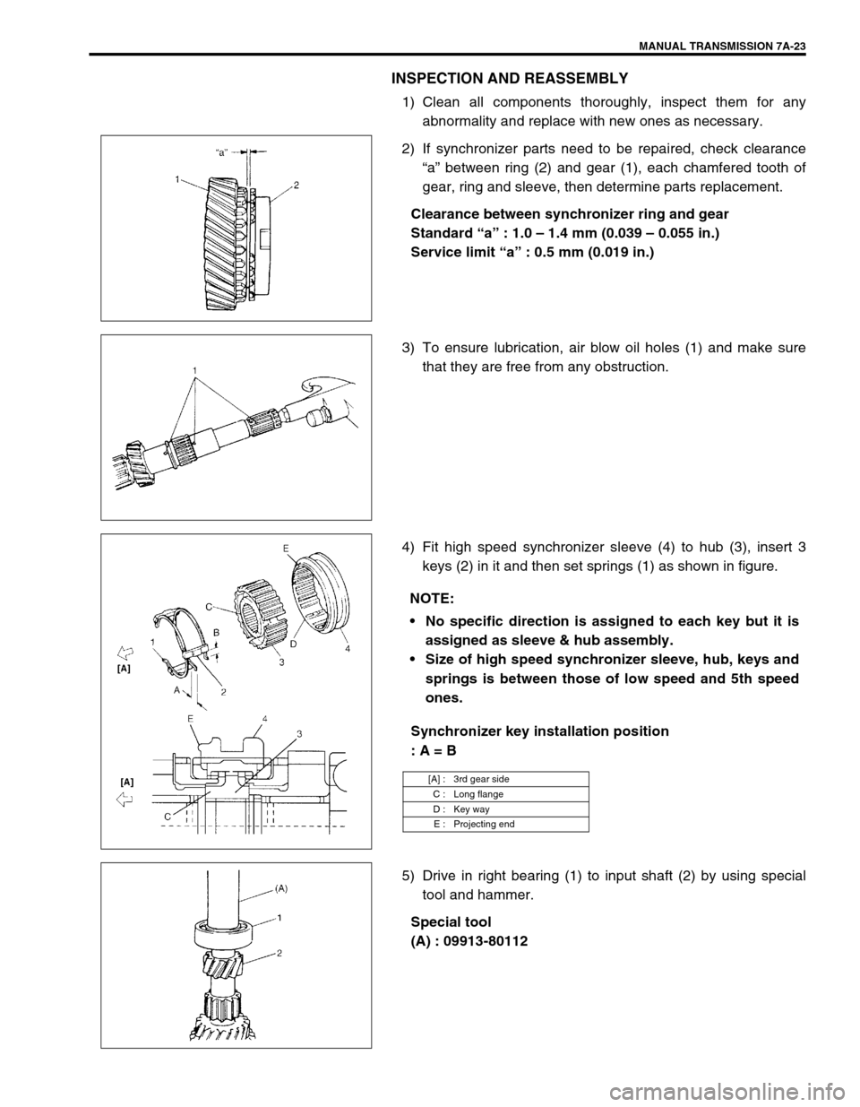
2) If synchronizer parts need to be repaired, check clearance
“a” between ring (2) and gear (1), each chamfered tooth of
gear, ring and sleeve, then determine parts replacement.
Clearance between synchronizer ring and gear
Standard “a” : 1.0 – 1.4 mm (0.039 – 0.055 in.)
Service limit “a” : 0.5 mm (0.019 in.)
3) To ensure lubrication, air blow oil holes (1) and make sure
that they are free from any obstruction.
4) Fit high speed synchronizer sleeve (4) to hub (3), insert 3
keys (2) in it and then set springs (1) as shown in figure.
Synchronizer key installation position
: A = B
5) Drive in right bearing (1) to input shaft (2) by using special
tool and hammer.
Special tool
(A) : 09913-80112
NOTE:
No specific direction is assigned to each key but it is
assigned as sleeve & hub assembly.
Size of high speed synchronizer sleeve, hub, keys and
springs is between those of low speed and 5th speed
ones.
[A] : 3rd gear side
C : Long flange
D : Key way
E : Projecting end
Page 24 of 447
7A-24 MANUAL TRANSMISSION
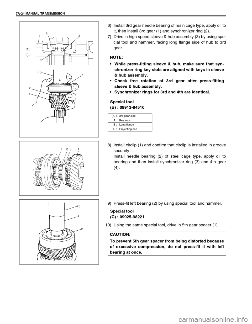
6) Install 3rd gear needle bearing of resin cage type, apply oil to
it, then install 3rd gear (1) and synchronizer ring (2).
7) Drive in high speed sleeve & hub assembly (3) by using spe-
cial tool and hammer, facing long flange side of hub to 3rd
gear.
Special tool
(B) : 09913-84510
8) Install circlip (1) and confirm that circlip is installed in groove
securely.
Install needle bearing (2) of steel cage type, apply oil to
bearing and then install synchronizer ring (3) and 4th gear
(4).
9) Press-fit left bearing (2) by using special tool and hammer.
Special tool
(C) : 09925-98221
10) Using the same special tool, drive in 5th gear spacer (1).NOTE:
While press-fitting sleeve & hub, make sure that syn-
chronizer ring key slots are aligned with keys in sleeve
& hub assembly.
Check free rotation of 3rd gear after press-fitting
sleeve & hub assembly.
Synchronizer rings for 3rd and 4th are identical.
[A] : 3rd gear side
A : Key way
B : Long flange
C : Projecting end
CAUTION:
To prevent 5th gear spacer from being distorted because
of excessive compression, do not press-fit it with left
bearing at once.
Page 25 of 447
MANUAL TRANSMISSION 7A-25
COUNTER SHAFT ASSEMBLY
DISASSEMBLY
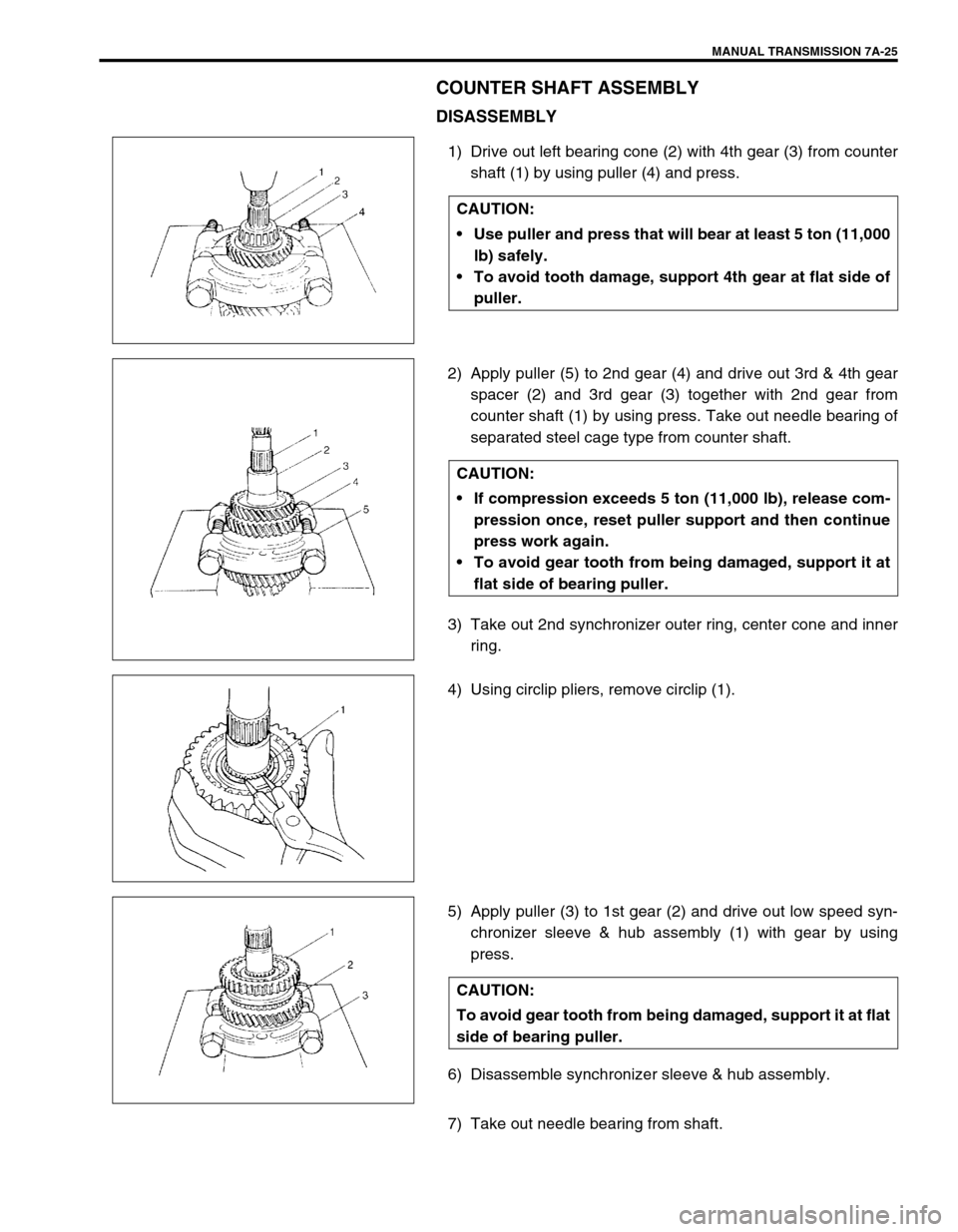
1) Drive out left bearing cone (2) with 4th gear (3) from counter
shaft (1) by using puller (4) and press.
2) Apply puller (5) to 2nd gear (4) and drive out 3rd & 4th gear
spacer (2) and 3rd gear (3) together with 2nd gear from
counter shaft (1) by using press. Take out needle bearing of
separated steel cage type from counter shaft.
3) Take out 2nd synchronizer outer ring, center cone and inner
ring.
4) Using circlip pliers, remove circlip (1).
5) Apply puller (3) to 1st gear (2) and drive out low speed syn-
chronizer sleeve & hub assembly (1) with gear by using
press.
6) Disassemble synchronizer sleeve & hub assembly.
7) Take out needle bearing from shaft.CAUTION:
Use puller and press that will bear at least 5 ton (11,000
lb) safely.
To avoid tooth damage, support 4th gear at flat side of
puller.
CAUTION:
If compression exceeds 5 ton (11,000 lb), release com-
pression once, reset puller support and then continue
press work again.
To avoid gear tooth from being damaged, support it at
flat side of bearing puller.
CAUTION:
To avoid gear tooth from being damaged, support it at flat
side of bearing puller.
Page 26 of 447
7A-26 MANUAL TRANSMISSION
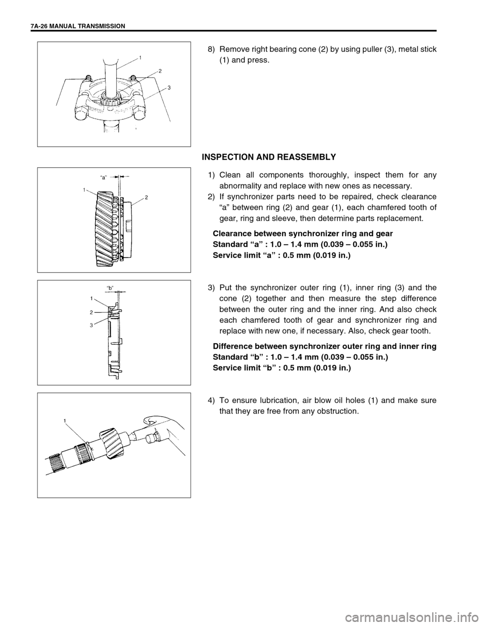
8) Remove right bearing cone (2) by using puller (3), metal stick
(1) and press.
INSPECTION AND REASSEMBLY
1) Clean all components thoroughly, inspect them for any
abnormality and replace with new ones as necessary.
2) If synchronizer parts need to be repaired, check clearance
“a” between ring (2) and gear (1), each chamfered tooth of
gear, ring and sleeve, then determine parts replacement.
Clearance between synchronizer ring and gear
Standard “a” : 1.0 – 1.4 mm (0.039 – 0.055 in.)
Service limit “a” : 0.5 mm (0.019 in.)
3) Put the synchronizer outer ring (1), inner ring (3) and the
cone (2) together and then measure the step difference
between the outer ring and the inner ring. And also check
each chamfered tooth of gear and synchronizer ring and
replace with new one, if necessary. Also, check gear tooth.
Difference between synchronizer outer ring and inner ring
Standard “b” : 1.0 – 1.4 mm (0.039 – 0.055 in.)
Service limit “b” : 0.5 mm (0.019 in.)
4) To ensure lubrication, air blow oil holes (1) and make sure
that they are free from any obstruction.
Page 27 of 447
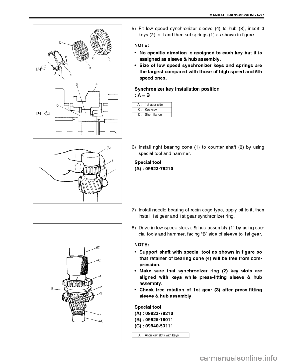
MANUAL TRANSMISSION 7A-27
5) Fit low speed synchronizer sleeve (4) to hub (3), insert 3
keys (2) in it and then set springs (1) as shown in figure.
Synchronizer key installation position
: A = B
6) Install right bearing cone (1) to counter shaft (2) by using
special tool and hammer.
Special tool
(A) : 09923-78210
7) Install needle bearing of resin cage type, apply oil to it, then
install 1st gear and 1st gear synchronizer ring.
8) Drive in low speed sleeve & hub assembly (1) by using spe-
cial tools and hammer, facing “B” side of sleeve to 1st gear.
Special tool
(A) : 09923-78210
(B) : 09925-18011
(C) : 09940-53111 NOTE:
No specific direction is assigned to each key but it is
assigned as sleeve & hub assembly.
Size of low speed synchronizer keys and springs are
the largest compared with those of high speed and 5th
speed ones.
[A] : 1st gear side
C : Key way
D : Short flange
NOTE:
Support shaft with special tool as shown in figure so
that retainer of bearing cone (4) will be free from com-
pression.
Make sure that synchronizer ring (2) key slots are
aligned with keys while press-fitting sleeve & hub
assembly.
Check free rotation of 1st gear (3) after press-fitting
sleeve & hub assembly.
A : Align key slots with keys
Page 28 of 447
7A-28 MANUAL TRANSMISSION
9) Install circlip (1) and confirm that circlip is installed in groove
securely.
Install needle bearing (2) of separated steel cage type, apply
oil to bearing.
With synchronizer outer ring (3), center cone (4) & inner ring
(5) put together and installed to 2nd gear (6) as shown in fig-
ure.
10) Press-fit 3rd gear (2) and spacer (1) by using special tools
and press.
Special tool
(A) : 09923-78210
(D) : 09913-80112
11) Press-fit 4th gear (2) by using the same procedure as the
above.
12) Install left bearing cone (1) by using special tools and ham-
mer.
Special tool
(A) : 09923-78210
(E) : 09925-98221
[A] : SECTION A - A
CAUTION:
Press-fit 3rd gear and spacer first, and then 4th gear later
separately so that counter shaft will not be compressed
excessively.
NOTE:
For protection of right bearing cone (3), always support
shaft with special tool as illustrated.