Page 130 of 447

7B-88 AUTOMATIC TRANSMISSION (4 A/T)
DISASSEMBLY/ASSEMBLY OF SUBASSEMBLY
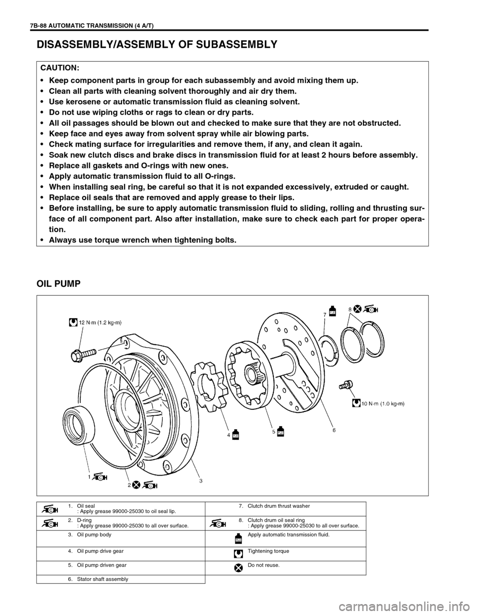
OIL PUMP
CAUTION:
Keep component parts in group for each subassembly and avoid mixing them up.
Clean all parts with cleaning solvent thoroughly and air dry them.
Use kerosene or automatic transmission fluid as cleaning solvent.
Do not use wiping cloths or rags to clean or dry parts.
All oil passages should be blown out and checked to make sure that they are not obstructed.
Keep face and eyes away from solvent spray while air blowing parts.
Check mating surface for irregularities and remove them, if any, and clean it again.
Soak new clutch discs and brake discs in transmission fluid for at least 2 hours before assembly.
Replace all gaskets and O-rings with new ones.
Apply automatic transmission fluid to all O-rings.
When installing seal ring, be careful so that it is not expanded excessively, extruded or caught.
Replace oil seals that are removed and apply grease to their lips.
Before installing, be sure to apply automatic transmission fluid to sliding, rolling and thrusting sur-
face of all component part. Also after installation, make sure to check each part for proper opera-
tion.
Always use torque wrench when tightening bolts.
1. Oil seal
: Apply grease 99000-25030 to oil seal lip.7. Clutch drum thrust washer
2. D-ring
: Apply grease 99000-25030 to all over surface. 8. Clutch drum oil seal ring
: Apply grease 99000-25030 to all over surface.
3. Oil pump body Apply automatic transmission fluid.
4. Oil pump drive gear Tightening torque
5. Oil pump driven gear Do not reuse.
6. Stator shaft assembly
Page 132 of 447
7B-90 AUTOMATIC TRANSMISSION (4 A/T)
ASSEMBLY
1) Install pump body oil seal (1)
Use special tool and hammer to install it, and then apply
grease to its lip portion.
Special tool
(A) : 09913-85210
“A”: Grease 99000-25030
2) Install driven gear and drive gear to pump body (2) after
applying A/T fluid to gears.
3) Install stator shaft assembly to pump body and tighten 11
pump cover bolts to specification.
Tightening torque
Oil pump cover bolts (a) : 10 N·m (1.0 kg-m, 7.5 lb-ft)
4) Install 2 new oil seal rings to stator shaft.
5) Apply grease to 2 oil seal rings.
6) Install new D-ring to which grease is applied and make sure
that it is not twisted or extruded.
7) Check drive gear for smooth rotation.
Page 133 of 447
AUTOMATIC TRANSMISSION (4 A/T) 7B-91
FRONT CLUTCH (C2 CLUTCH)
DISASSEMBLY
1) Remove snap ring.
2) Remove flange (1), discs and plates.
3) Remove shaft snap ring (1).
Compress piston return springs and remove shaft snap ring.
Place special tool (clutch spring compressor) on spring seat
and compress spring with a press (2), and then remove shaft
snap ring, using a flat end rod or the like (3).
Special tool
(A) : 09926-96010
1. Front clutch No.1 drum 7. Clutch plate
2. D-ring
: Apply grease 99000-25030 to all over surface.8. Clutch disc
3. Front clutch piston
: Apply grease 99000-25030 to the lip of the piston.9. Clutch flange
4. Front clutch return spring seat 10. Snap ring
5. Front clutch balancer Apply automatic transmission fluid.
6. Shaft snap ring Do not reuse.
CAUTION:
Do not push down return spring more than necessary.
Page 134 of 447

7B-92 AUTOMATIC TRANSMISSION (4 A/T)
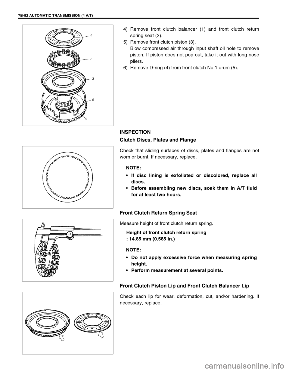
4) Remove front clutch balancer (1) and front clutch return
spring seat (2).
5) Remove front clutch piston (3).
Blow compressed air through input shaft oil hole to remove
piston. If piston does not pop out, take it out with long nose
pliers.
6) Remove D-ring (4) from front clutch No.1 drum (5).
INSPECTION
Clutch Discs, Plates and Flange
Check that sliding surfaces of discs, plates and flanges are not
worn or burnt. If necessary, replace.
Front Clutch Return Spring Seat
Measure height of front clutch return spring.
Height of front clutch return spring
: 14.85 mm (0.585 in.)
Front Clutch Piston Lip and Front Clutch Balancer Lip
Check each lip for wear, deformation, cut, and/or hardening. If
necessary, replace.
NOTE:
If disc lining is exfoliated or discolored, replace all
discs.
Before assembling new discs, soak them in A/T fluid
for at least two hours.
NOTE:
Do not apply excessive force when measuring spring
height.
Perform measurement at several points.
Page 135 of 447

AUTOMATIC TRANSMISSION (4 A/T) 7B-93
ASSEMBLY
1) Install new D-ring (5) to front clutch No.1 drum.
Apply grease to D-ring and fit it to drum.
“A” : Grease 99000-25030
2) Install piston (4) into front clutch No.1 drum (6).
Use care that the piston lip does not get twisted or caught.
Apply grease to the lip of the piston.
“A” : Grease 99000-25030
3) Install front clutch return spring (3) seat and front clutch bal-
ancer (2).
4) Install shaft snap ring (1).
Compress return springs and install shaft snap ring in groove
by using a flat end rod or the like (3).
Place special tool (clutch spring compressor) on spring seat
and compress springs with a press (2).
Special tool
(A) : 09926-96010
5) Install discs, plates and flange (1) in following order.
(1) Plate →
(2) Disc →
(3) Plate →
(4) Disc →
(5) Plate →
(6) Disc →
(7) Plate →
(8) Disc →
(9) Flange
1. Snap ring
CAUTION:
Do not compress return spring more than necessary.
NOTE:
Before assembly, new discs should be soaked in auto-
matic transmission fluid for at least 2 hours.
Page 137 of 447
AUTOMATIC TRANSMISSION (4 A/T) 7B-95
10) Attach special tool (B) to dial gauge (2) and set them on the
lowest clutch plate.
Special tool
(B) : 09952-06010
11) Measure piston stroke by blowing compressed air (4 kg/cm
2,
57 psi) as shown in figure.
If the piston stroke is out of specification, replace clutch
discs, plates and flange.
Front clutch piston stroke
: 1.46 – 1.64 mm (0.0575 – 0.0646 in.)
REAR CLUTCH (C1 CLUTCH)
1. Front clutch assembly
3. Air gun
1. Input shaft oil seal ring
: Apply grease 99000-25030 to all over surface.8. Clutch plate
2. Input shaft subassembly 9. Clutch disc
3. D-ring
: Apply grease 99000-25030 to all over surface.10. Clutch flange
4. Rear clutch piston
: Apply grease 99000-25030 to the lip of the piston.11. Snap ring
5. Rear clutch return spring seat Apply automatic transmission fluid.
6. Rear clutch balancer Do not reuse.
7. Shaft snap ring
Page 138 of 447

7B-96 AUTOMATIC TRANSMISSION (4 A/T)
DISASSEMBLY
1) Remove snap ring.
2) Remove flange (1), discs and plates.
3) Remove shaft snap ring (1).
Compress piston return springs and remove shaft snap ring.
Place special tool (clutch spring compressor) on spring seat
and compress spring with a press (2), and then remove shaft
snap ring, using a flat end rod or the like (3).
Special tool
(A) : 09926-96020
4) Remove rear clutch balancer (1) and rear clutch return
spring seat (2).
5) Remove rear clutch piston (3).
If piston does not pop out, blow compressed air through
input shaft oil hole to remove piston.
6) Remove D-ring, and oil seals from input shaft subassembly
(4).
INSPECTION
Clutch Discs, Plates and Flange
Check that sliding surfaces of discs, plates and flanges are not
worn or burnt. If necessary, replace.
CAUTION:
Do not push down return spring more than necessary.
NOTE:
If disc lining is exfoliated or discolored, replace all
discs.
Before assembling new discs, soak them in A/T fluid
for at least two hours.
Page 140 of 447
7B-98 AUTOMATIC TRANSMISSION (4 A/T)
5) Install discs, plates and flange (1) in following order.
(1) Plate →
(2) Disc →
(3) Plate →
(4) Disc →
(5) Plate →
(6) Disc →
(7) Plate →
(8) Disc →
(9) Plate →
(10) Disc →
(11) Flange
6) Install snap ring (1).NOTE:
Before assembly, new discs should be soaked in auto-
matic transmission fluid for at least 2 hours.
NOTE:
Make sure that the ends of the snap ring do not come to
the opening of the input shaft subassembly.