Page 347 of 447

BODY SERVICE 9-43
INSTALLATION
Reverse removal procedure to install front door lock assembly
noting the following instructions.
Apply grease to sliding parts of door latch assembly.
Grease 99000-25010
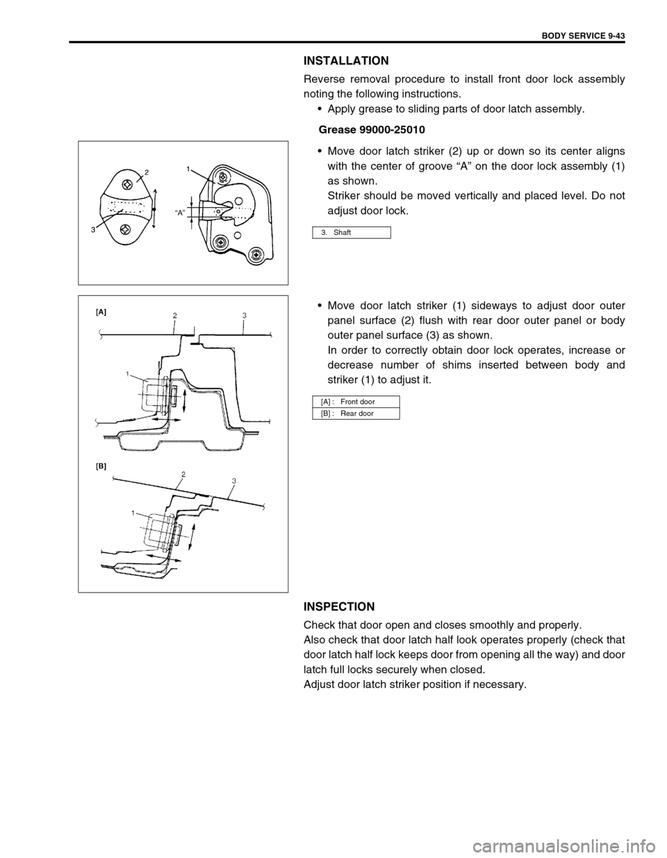
Move door latch striker (2) up or down so its center aligns
with the center of groove “A” on the door lock assembly (1)
as shown.
Striker should be moved vertically and placed level. Do not
adjust door lock.
Move door latch striker (1) sideways to adjust door outer
panel surface (2) flush with rear door outer panel or body
outer panel surface (3) as shown.
In order to correctly obtain door lock operates, increase or
decrease number of shims inserted between body and
striker (1) to adjust it.
INSPECTION
Check that door open and closes smoothly and properly.
Also check that door latch half look operates properly (check that
door latch half lock keeps door from opening all the way) and door
latch full locks securely when closed.
Adjust door latch striker position if necessary.
3. Shaft
[A] : Front door
[B] : Rear door
Page 350 of 447

9-46 BODY SERVICE
5) Remove back door licence garnish (1).
6) Remove back door lock cylinder (2).
INSTALLATION
Reverse removal procedure to install back door lock assembly
noting the following instruction.
Adjust door latch striker so that its center aligns with the cen-
ter of groove in door latch base.
INSPECTION
Check that door open and closes smoothly and properly.
Also check that door latch half lock operates properly (Check that
door latch half lock keeps door from opening all the way) and door
latch full locks securely closed.
Adjust door latch striker position if necessary.
KEY CODING
KEY USAGE AND IDENTIFICATION
Key is used for ignition and door lock cylinder. Keys are cut on
both edges to make them reversible.
Key identification is obtained from five character key code
stamped on key code tag. Using this key code, key code cutting
combination can be determined from a code list (available to own-
ers of key cutting equipment from suppliers).
If key codes are not available from records or tags, key code can
be obtained from the right hand door lock cylinder (if lock has not
been replaced). Lock cylinders supplied by the factory as service
parts are unmarked.
If original key is available, key code cutting combination can be
determined by laying key.
2
1
Page 372 of 447

10-6 RESTRAINT SYSTEM
REMOVAL
1) Disconnect negative battery cable at battery.
2) Disable air bag system. Refer to “DISABLING AIR BAG SYSTEM” of “SERVICE PRECAUTIONS” under
“ON-VEHICLE SERVICE” in Section 10B.
3) Remove center pillar lower trim.
4) Disconnect Yellow connector for seat belt pretensioner.
a) Release locking of lock lever.
b) After unlocked, disconnect to connector.
5) Remove front seat belts from the vehicle.
INSPECTION
Seat belts and attaching parts can affect the vital components
and systems of a vehicle.
Therefore, they should be inspected carefully and replaced with
genuine parts only.
Seat belt
Its webbing or strap should be free from damage.
Retractor assembly
It should lock webbing when pulled quickly.
The front seat belt retractor assembly (1) should pass the
above inspection and should lock webbing even when tilted
(approx. 15°) toward the fore and aft or right and left direc-
tions.
Check retractor assembly (1) with seat belt pretensioner
appearance visually for following symptoms and if any one of
them is applicable, replace it with a new one as an assem-
bly.
Pretensioner has activated.
There is a crack in seat belt pretensioner (retractor assem-
bly).
Wire harness or connector (2) is damaged.
Seat belt pretensioner (retractor assembly) is damaged or a
strong impact (e.g., dropping) was applied to it.
Anchor bolt
Anchor bolts should be torqued to specification.
Belt latch
It should be secure when latched. WARNING:
Never measure resistance of pretensioner or disassem-
ble it. Otherwise, personal injury may result.
CAUTION:
If seat belt pretensioner (retractor assembly) was
dropped from a height of 30 cm (1 ft) or more, it should
be replaced.
Page 373 of 447
RESTRAINT SYSTEM 10-7
INSTALLATION
Install in reverse order of removal, noting the following.
Seat belt anchor bolts should have an unified fine thread (7/
16-20 UNF). Under no circumstances should any different
sized or metric screw threads be used.
Connect Yellow connector (1) for seat belt pretensioner
securely and fit seat belt pretensioner connector onto body.
a) Connect connector
b) Lock connector with lock lever
Enable air bag system. Refer to “ENABLING AIR BAG SYS-
TEM” under “SERVICE PRECAUTIONS” in Section 10B.
Page 394 of 447

10B-20 AIR BAG SYSTEM
Table D :
Fig. for STEP 2
Special tool
(A) : 09932-76010 Step Action Yes No
1 1) Inspect connection between diagnostic
switch terminal on “AIR BAG” monitor cou-
pler and body ground by service wire.
Is it securely connected between them by ser-
vice wire?Go to step 2. Properly connection diag-
nostic switch terminal on
“AIR BAG” monitor cou-
pler and body ground by
service wire.
2 1) Disconnect SDM connector from SDM.
2) Check for proper connection at “PPL” wire
(“Q06-15” terminal of SDM connector and
“Q04-2” terminal of “AIR BAG” monitor cou-
pler) terminals.
3) If OK then measure resistance between
“Q06-15” terminal and “Q04-2” terminal.
Is resistance 1 Ω or more?Check “PPL” wire termi-
nals.
If OK then “PPL” wire cir-
cuit high resistance or
open.Substitute a known good
SDM and recheck
1.“AIR BAG” monitor coupler
2.“PPL” wire terminal
NOTE:
Upon completion of inspection and repair work, perform following items.
Reconnect all air bag system components, ensure all components are properly mounted.
Repeat AIR BAG DIAGNOSTIC SYSTEM CHECK to confirm that the trouble has been corrected.
Page 418 of 447

10B-44 AIR BAG SYSTEM
Fig. for STEP 2
Special tool
(A) : 09932-76010
(B) : 09932-75010
DTC B1051 – FRONTAL CRASH DETECTED (SYSTEM ACTIVATION COM-
MAND OUTPUTTED)
DTC WILL SET WHEN
The SDM detects a frontal crash of sufficient force to warrant activation of the air bag system. (SDM outputs a
deployment command.)
TABLE TEST DESCRIPTION
STEP 1 : Check that DTC B1051 has been set although air bag has not been deployed.
STEP 2 : Check that DTC has been set due to failure of SDM.
[A] : For DTC B1044
[B] : For DTC B1048
NOTE:
Upon completion of inspection and repair work, perform following items.
Reconnect all air bag system components, ensure all components are properly mounted.
Clear diagnostic trouble codes (Refer to DTC CLEARANCE), if any.
Repeat AIR BAG DIAGNOSTIC SYSTEM CHECK to confirm that the trouble has been corrected.
NOTE:
Before executing items in this table, be sure to perform AIR BAG DIAGNOSTIC SYSTEM CHECK.
Step Action Yes No
1 1) Ignition switch OFF.
Has air bag system deployed?Replace components and
perform inspections as
directed in “REPAIRS
AND INSPECTIONS
REQUIRED AFTER AN
ACCIDENT”.Go to step 2.
Page 419 of 447

AIR BAG SYSTEM 10B-45
DTC B1071 - INTERNAL SDM FAULT
DTC WILL SET WHEN
An internal SDM fault is detected by SDM.
DTC B1013 – SYSTEM SPECIFICATIONS DIFFERENT FROM SDM SPECIFICA-
TIONS
DTC WILL SET WHEN
Specifications of the air bag system differ from those of SDM.2 1) Inspect front of vehicle and undercarriage
for signs of impact.
Are there signs of impact?Replace components and
perform inspections as
directed in “REPAIRS
AND INSPECTIONS
REQUIRED AFTER AN
ACCIDENT”.Substitute a known-good
SDM and recheck. Step Action Yes No
NOTE:
Upon completion of inspection and repair work, perform following items.
Reconnect all air bag system components, ensure all components are properly mounted.
Repeat AIR BAG DIAGNOSTIC SYSTEM CHECK to confirm that the trouble has been corrected.
NOTE:
Before executing items below, be sure to perform AIR BAG DIAGNOSTIC SYSTEM CHECK.
NOTE:
DTC B1071 can never be cleared once it has been set.
Ignition switch OFF.
Replace SDM.
Repeat AIR BAG DIAGNOSTIC SYSTEM CHECK.
NOTE:
Before executing items below, be sure to perform AIR BAG DIAGNOSTIC SYSTEM CHECK.
Ignition switch OFF.
Replace SDM.
Repeat AIR BAG DIAGNOSTIC SYSTEM CHECK.
Page 424 of 447

10B-50 AIR BAG SYSTEM
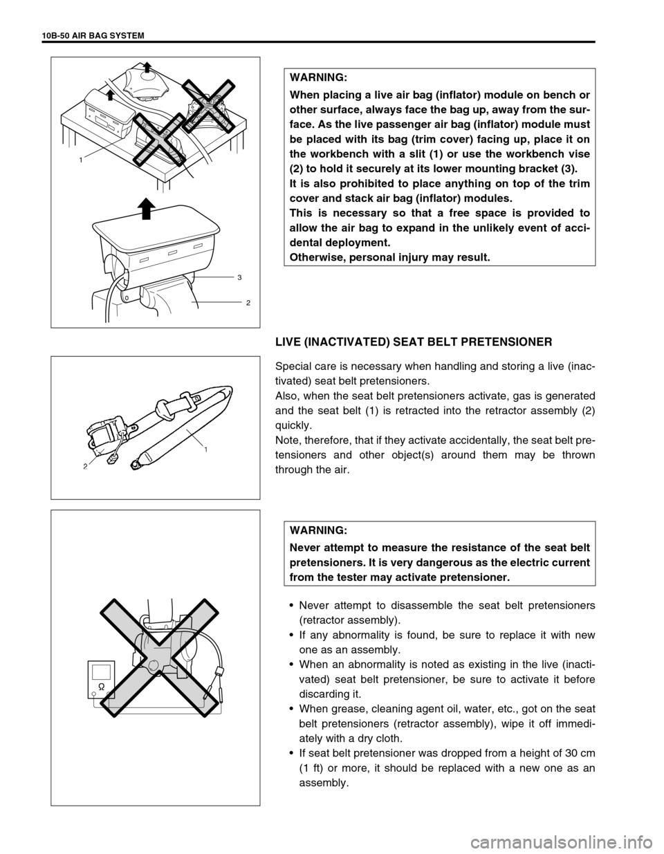
LIVE (INACTIVATED) SEAT BELT PRETENSIONER
Special care is necessary when handling and storing a live (inac-
tivated) seat belt pretensioners.
Also, when the seat belt pretensioners activate, gas is generated
and the seat belt (1) is retracted into the retractor assembly (2)
quickly.
Note, therefore, that if they activate accidentally, the seat belt pre-
tensioners and other object(s) around them may be thrown
through the air.
Never attempt to disassemble the seat belt pretensioners
(retractor assembly).
If any abnormality is found, be sure to replace it with new
one as an assembly.
When an abnormality is noted as existing in the live (inacti-
vated) seat belt pretensioner, be sure to activate it before
discarding it.
When grease, cleaning agent oil, water, etc., got on the seat
belt pretensioners (retractor assembly), wipe it off immedi-
ately with a dry cloth.
If seat belt pretensioner was dropped from a height of 30 cm
(1 ft) or more, it should be replaced with a new one as an
assembly. WARNING:
When placing a live air bag (inflator) module on bench or
other surface, always face the bag up, away from the sur-
face. As the live passenger air bag (inflator) module must
be placed with its bag (trim cover) facing up, place it on
the workbench with a slit (1) or use the workbench vise
(2) to hold it securely at its lower mounting bracket (3).
It is also prohibited to place anything on top of the trim
cover and stack air bag (inflator) modules.
This is necessary so that a free space is provided to
allow the air bag to expand in the unlikely event of acci-
dental deployment.
Otherwise, personal injury may result.
1
2 3
WARNING:
Never attempt to measure the resistance of the seat belt
pretensioners. It is very dangerous as the electric current
from the tester may activate pretensioner.