Page 115 of 447
AUTOMATIC TRANSMISSION (4 A/T) 7B-73
REMOVAL
1) Disconnect negative cable at battery and disable air bag sys-
tem, referring to “DISABLING AIR BAG SYSTEMS” in Sec-
tion 10B (if equipped).
2) Remove steering column hole cover and steering column
cover.
3) Remove steering column mounting bolts and nuts.
4) Remove interlock cable screw (1) located at ignition switch
and disconnect interlock cable (2) from key cylinder arm (3)
with ignition switch turned to “ACC” position.
5) Remove center console.
6) Remove cable end (1) from key interlock cam (2) and its
bracket (3).
7) Remove interlock cable (4).
INSTALLATION
1) Install interlock cable (1) to pedal brackets (2) by clamp as
shown in figure.
2) With ignition key at “ACC” position, connect cable end (1) to
key cylinder arm (2) and tighten cable screw (3) securely.
Page 184 of 447

7C-2 CLUTCH
GENERAL DESCRIPTION
The clutch is a diaphragm-spring clutch of a dry single disc type. The diaphragm spring is of a tapering-finger
type, which is a solid ring in the outer diameter part, with a series of tapered fingers pointing inward.
The disc, carrying four torsional coil springs, is positioned on the transmission input shaft with an involute spline
fit.
The clutch cover is secured to the flywheel, and carries the diaphragm spring in such a way that the peripheral
edge part of the spring pushes on the pressure plate against the flywheel (with the disc in between), when the
clutch release bearing is held back. This is the engaged condition of the clutch.
Depressing the clutch pedal causes the release bearing to advance and pushes on the tips of the tapered fin-
gers of the diaphragm spring. When this happens, the diaphragm spring pulls the pressure plate away from the
flywheel, thereby interrupting the flow of drive from flywheel through clutch disc to transmission input shaft.
1. Crankshaft 6. Diaphragm spring
2. Flywheel 7. Release bearing
3. Clutch disc 8. Input shaft bearing
4. Pressure plate 9. Input shaft
5. Clutch cover 10. Release shaft
Page 202 of 447

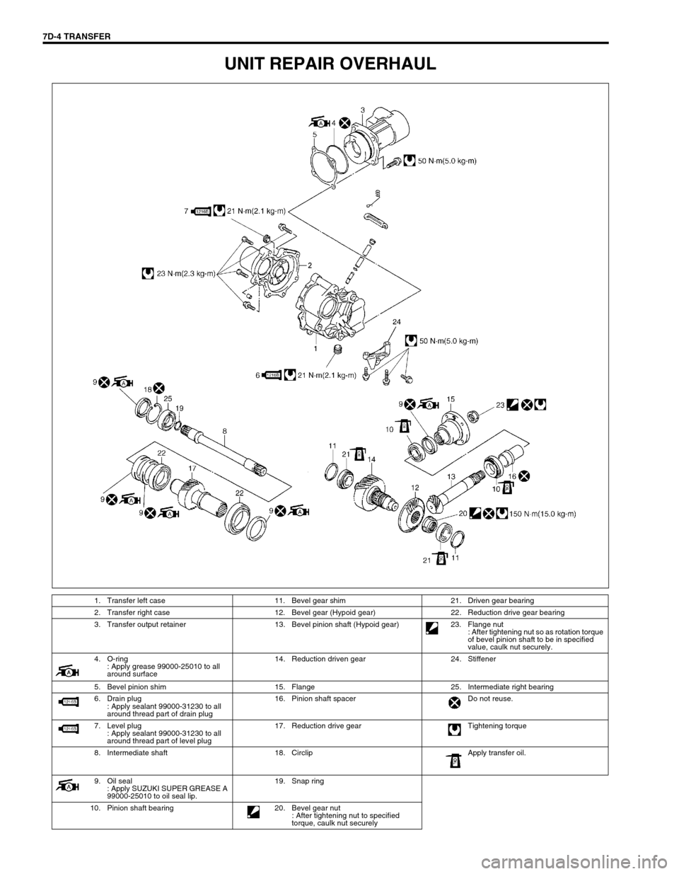
7D-4 TRANSFER
UNIT REPAIR OVERHAUL
1. Transfer left case 11. Bevel gear shim 21. Driven gear bearing
2. Transfer right case 12. Bevel gear (Hypoid gear) 22. Reduction drive gear bearing
3. Transfer output retainer 13. Bevel pinion shaft (Hypoid gear) 23. Flange nut
: After tightening nut so as rotation torque
of bevel pinion shaft to be in specified
value, caulk nut securely.
4. O-ring
: Apply grease 99000-25010 to all
around surface14. Reduction driven gear 24. Stiffener
5. Bevel pinion shim 15. Flange 25. Intermediate right bearing
6. Drain plug
: Apply sealant 99000-31230 to all
around thread part of drain plug16. Pinion shaft spacer Do not reuse.
7. Level plug
: Apply sealant 99000-31230 to all
around thread part of level plug17. Reduction drive gear Tightening torque
8. Intermediate shaft 18. Circlip Apply transfer oil.
9. Oil seal
: Apply SUZUKI SUPER GREASE A
99000-25010 to oil seal lip.19. Snap ring
10. Pinion shaft bearing 20. Bevel gear nut
: After tightening nut to specified
torque, caulk nut securely
Page 225 of 447
REAR DIFFERENTIAL 7F-3
DIAGNOSIS
Condition Possible Cause Correction
Gear noise
Deteriorated or water mixed lubricant Repair and replenish.
Inadequate or insufficient lubricant Repair and replenish.
Maladjusted backlash between bevel pinion
and gearAdjust and prescribed.
Improper tooth contact in the mesh between
bevel pinion and gearAdjust or replace.
Loose bevel gear securing bolts Replace or retighten.
Damaged side gear(s) or side pinion(s) Replace.
Bearing noise
(Constant noise) Deteriorated or water mixed
lubricantRepair or replenish.
(Constant noise) Inadequate or insufficient
lubricantRepair or replenish.
(Noise while coasting) Damaged bearing(s) of
bevel pinionReplace.
(Noise while turning) Damaged differential side
bearing(s)Replace.
Oil leakage
Clogged breather plug Clean.
Worn or damaged oil seal Replace.
Excessive oil Adjust oil level.
Page 227 of 447

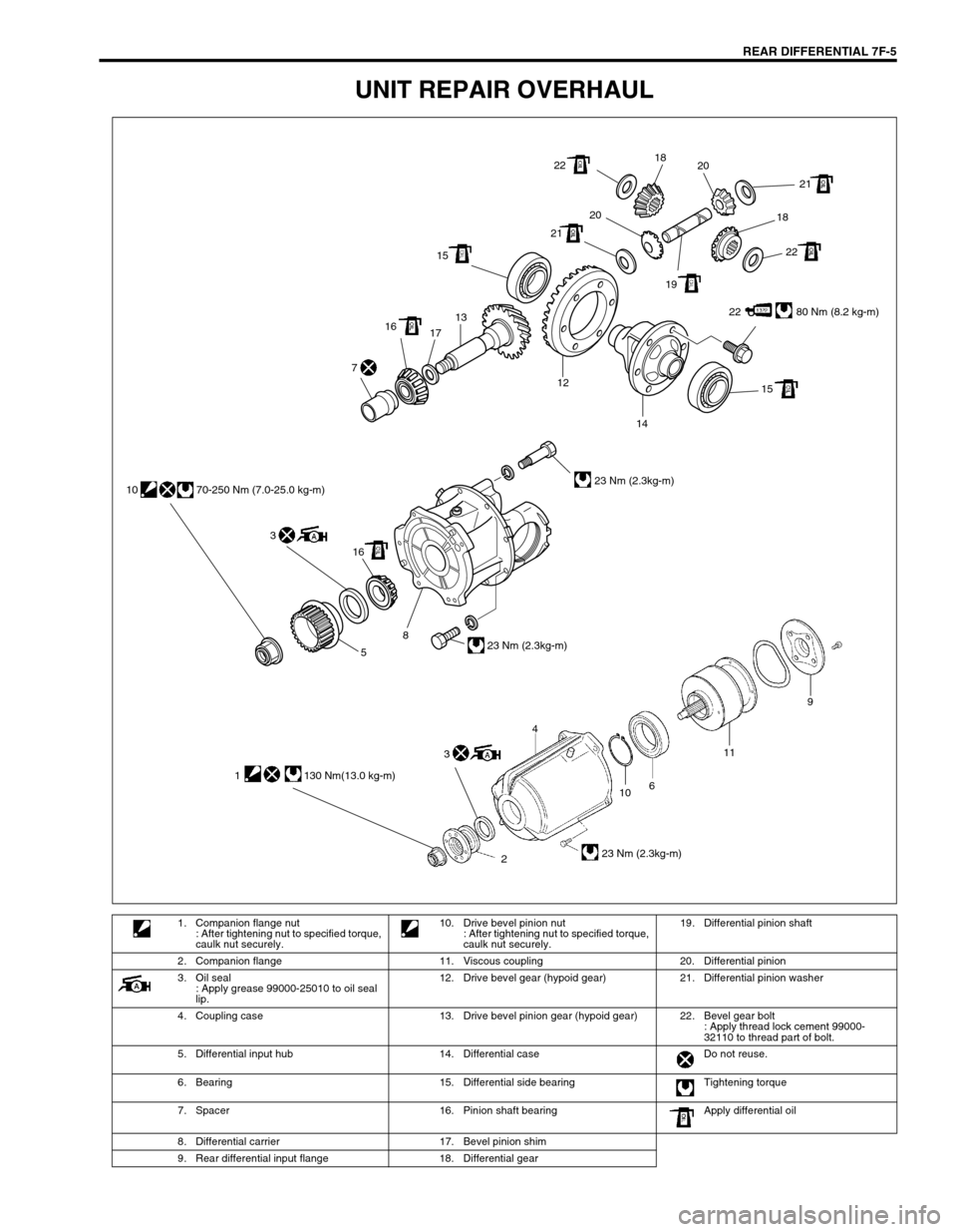
REAR DIFFERENTIAL 7F-5
UNIT REPAIR OVERHAUL
22 80 Nm (8.2 kg-m) 1513
17 16
15 12
14 7
22
22 2121
2020
1918 18
16 3 10 70-250 Nm (7.0-25.0 kg-m)
23 Nm (2.3kg-m)
23 Nm (2.3kg-m)
8
5
10
2611
23 Nm (2.3kg-m)
9
4
1 130 Nm(13.0 kg-m)
3
1. Companion flange nut
: After tightening nut to specified torque,
caulk nut securely.10. Drive bevel pinion nut
: After tightening nut to specified torque,
caulk nut securely.19. Differential pinion shaft
2. Companion flange 11. Viscous coupling 20. Differential pinion
3. Oil seal
: Apply grease 99000-25010 to oil seal
lip.12. Drive bevel gear (hypoid gear) 21. Differential pinion washer
4. Coupling case 13. Drive bevel pinion gear (hypoid gear) 22. Bevel gear bolt
: Apply thread lock cement 99000-
32110 to thread part of bolt.
5. Differential input hub 14. Differential case Do not reuse.
6. Bearing 15. Differential side bearing Tightening torque
7. Spacer 16. Pinion shaft bearing Apply differential oil
8. Differential carrier 17. Bevel pinion shim
9. Rear differential input flange 18. Differential gear
Page 301 of 447

IMMOBILIZER CONTROL SYSTEM 8G-23
HOW TO REGISTER IGNITION KEY
Register the ignition key with a built-in transponder in Immobilizer
Control Module by using the following procedure.
1) Prepare SUZUKI scan tool and cartridge for immobilizer con-
trol system.
2) With ignition switch OFF, connect SUZUKI scan tool to data
link connector (DLC) (1) located on underside of instrument
panel at driver’s seat side.
(A) : 09931-76011 (SUZUKI scan tool)
(B) : Immobilizer cartridge
(C) : 09931-76030 (16/14 pin DLC cable)
3) Prepare ignition key with a built-in transponder (1). And then
turn ignition switch ON by using it.
4) Number of Transponder codes for ignition key with a built-in
transponder that can be registered in Immobilizer Control
Module is limited to 4. If needed, clear all Transponder
codes for ignition key with a built-in transponder that have
been registered in Immobilizer Control Module by executing
the “CLR. TRANS COD (CLEAR TP CODE)” command in
the SELECT MODE menu by using SUZUKI scan tool. CAUTION:
When registering the ignition key including a transpon-
der into the immobilizer control module by using Suzuki
scan tool, confirm that the knob color of the ignition key
to be registered for the vehicle is dark gray. The ignition
key with wrong knob color cannot be registered.
NOTE:
For operation procedure of SUZUKI scan tool, refer to
SUZUKI scan tool operator’s manual.
1
(C)(A)
(B)
NOTE:
When “CLR. TRANS COD (CLEAR TP CODE)” command
is executed with the immobilizer indicator lamp ON, it
remains ON even after execution of that command is
over. It will start flashing when the ignition switch is
turned OFF once and then turned ON after some sec-
onds.
Page 302 of 447

8G-24 IMMOBILIZER CONTROL SYSTEM
5) Using SUZUKI scan tool, register Transponder code in
Immobilizer Control Module by executing “ENT. TRANS
COD (ENT. TP CODE)” command in SELECT MODE menu.
6) Make sure that immobilizer indicator lamp lights when igni-
tion switch is turned OFF once and then ON.
7) If any other Transponder code for ignition key with a built-in
transponder needs to be registered, repeat above steps 3),
5) and 6).
PROCEDURE AFTER IMMOBILIZER CONTROL MODULE
REPLACEMENT
When Immobilizer Control Module was replaced, including when replaced because rechecking by using a
known-good Immobilizer Control Module was necessary during trouble diagnosis, register Transponder code
and ECM/Immobilizer Control Module code in Immobilizer Control Module and ECM/Immobilizer Control Module
code in ECM by performing following procedure.
1) Perform steps 1) and 2) described in “How To Register Ignition Key”.
2) Prepare ignition key with a built-in transponder. And then turn ignition switch ON by using it.
3) Using SUZUKI scan tool, clear all transponder codes registered in Immobilizer Control Module by executing
“CLR. TRANS COD (CLEAR TP CODE)” command in SELECT MODE menu.
4) Using SUZUKI scan tool, register Transponder code in Immobilizer Control Module by executing “ENT.
TRANS COD (ENT. TP CODE)” command in SELECT MODE menu.
5) Using SUZUKI scan tool, register ECM/Immobilizer Control Module code in both Immobilizer Control Module
and ECM by executing “RECORD ECU (RECORD ECM/PCM/ICM)” command in SELECT MODE menu.
6) Make sure that immobilizer indicator lamp lights when ignition switch is turned OFF once and then ON.
7) If any other Transponder code for ignition key with a built-in transponder needs to be registered, repeat
above steps 2), 4) and 6).NOTE:
Up to 4 Transponder codes for ignition key with a built-
in transponder can be registered.
It is not possible to register the same Transponder
code for ignition key with a built-in transponder as the
one already registered in Immobilizer Control Module.
CAUTION:
When registering the ignition key including a transponder into the immobilizer control module by
using Suzuki scan tool, confirm that the knob color of the ignition key to be registered for the vehicle
is dark gray. The ignition key with wrong knob color cannot be registered.
NOTE:
When “CLR. TRANS COD (CLEAR TP CODE)” command is executed with the immobilizer indicator
lamp ON, it remains ON even after execution of that command is over. It will start flashing when the
ignition switch is turned OFF once and then turned ON after some seconds.
Page 303 of 447

IMMOBILIZER CONTROL SYSTEM 8G-25
PROCEDURE AFTER ECM REPLACEMENT
When ECM was replaced, including when replaced because rechecking by using a known-good ECM was nec-
essary during trouble diagnosis, register ECM/Immobilizer Control Module code in ECM by performing following
procedure.
1) Perform steps 1) and 2) described in “How To Register Ignition Key”. And then turn ignition switch ON.
2) Using SUZUKI scan tool, register ECM/Immobilizer Control Module code in ECM by executing “RECORD
ECU (RECORD ECM/lCM)” command in SELECT MODE menu.
3) Make sure that malfunction indicator lamp lights when ignition switch is turned OFF once and then ON.
SPECIAL TOOL
NOTE:
Up to 4 Transponder codes for ignition key with a built-in transponder can be registered.
It is not possible to register the same Transponder code for ignition key with a built-in transponder
as the one already registered in Immobilizer Control Module.
NOTE:
For operation procedure of SUZUKI scan tool, refer to SUZUKI scan tool operator’s manual.
09931-76011 09931-76030
Tech 1A kit
See NOTE below.Immobilizer cartridge of
version 1.1 or more16/14 pin DLC cable Mass storage cartridge of
version 1.5 or more
NOTE:
This kit includs the following items.
1. Storage case, 2. Operator’s manual, 3. Tech 1A, 4. DLC cable, 5. Test lead/probe,
6. Power source cable, 7. DLC cable adaptor, 8. Self-test adaptor