Page 28 of 447
7A-28 MANUAL TRANSMISSION
9) Install circlip (1) and confirm that circlip is installed in groove
securely.
Install needle bearing (2) of separated steel cage type, apply
oil to bearing.
With synchronizer outer ring (3), center cone (4) & inner ring
(5) put together and installed to 2nd gear (6) as shown in fig-
ure.
10) Press-fit 3rd gear (2) and spacer (1) by using special tools
and press.
Special tool
(A) : 09923-78210
(D) : 09913-80112
11) Press-fit 4th gear (2) by using the same procedure as the
above.
12) Install left bearing cone (1) by using special tools and ham-
mer.
Special tool
(A) : 09923-78210
(E) : 09925-98221
[A] : SECTION A - A
CAUTION:
Press-fit 3rd gear and spacer first, and then 4th gear later
separately so that counter shaft will not be compressed
excessively.
NOTE:
For protection of right bearing cone (3), always support
shaft with special tool as illustrated.
Page 30 of 447

7A-30 MANUAL TRANSMISSION
2) Insert each gear shift shaft into case and check that it moves
smoothly. If it doesn’t, correct by using oilstone, reamer or
the like.
5th & Reverse Gear Shifter
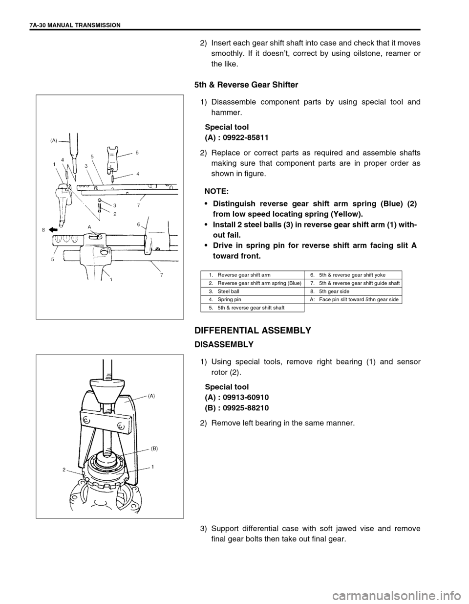
1) Disassemble component parts by using special tool and
hammer.
Special tool
(A) : 09922-85811
2) Replace or correct parts as required and assemble shafts
making sure that component parts are in proper order as
shown in figure.
DIFFERENTIAL ASSEMBLY
DISASSEMBLY
1) Using special tools, remove right bearing (1) and sensor
rotor (2).
Special tool
(A) : 09913-60910
(B) : 09925-88210
2) Remove left bearing in the same manner.
3) Support differential case with soft jawed vise and remove
final gear bolts then take out final gear. NOTE:
Distinguish reverse gear shift arm spring (Blue) (2)
from low speed locating spring (Yellow).
Install 2 steel balls (3) in reverse gear shift arm (1) with-
out fail.
Drive in spring pin for reverse shift arm facing slit A
toward front.
1. Reverse gear shift arm 6. 5th & reverse gear shift yoke
2. Reverse gear shift arm spring (Blue) 7. 5th & reverse gear shift guide shaft
3. Steel ball 8. 5th gear side
4. Spring pin A: Face pin slit toward 5thn gear side
5. 5th & reverse gear shift shaft
Page 33 of 447

MANUAL TRANSMISSION 7A-33
UNIT ASSEMBLY
DIFFERENTIAL TO LEFT CASE
ASSEMBLY
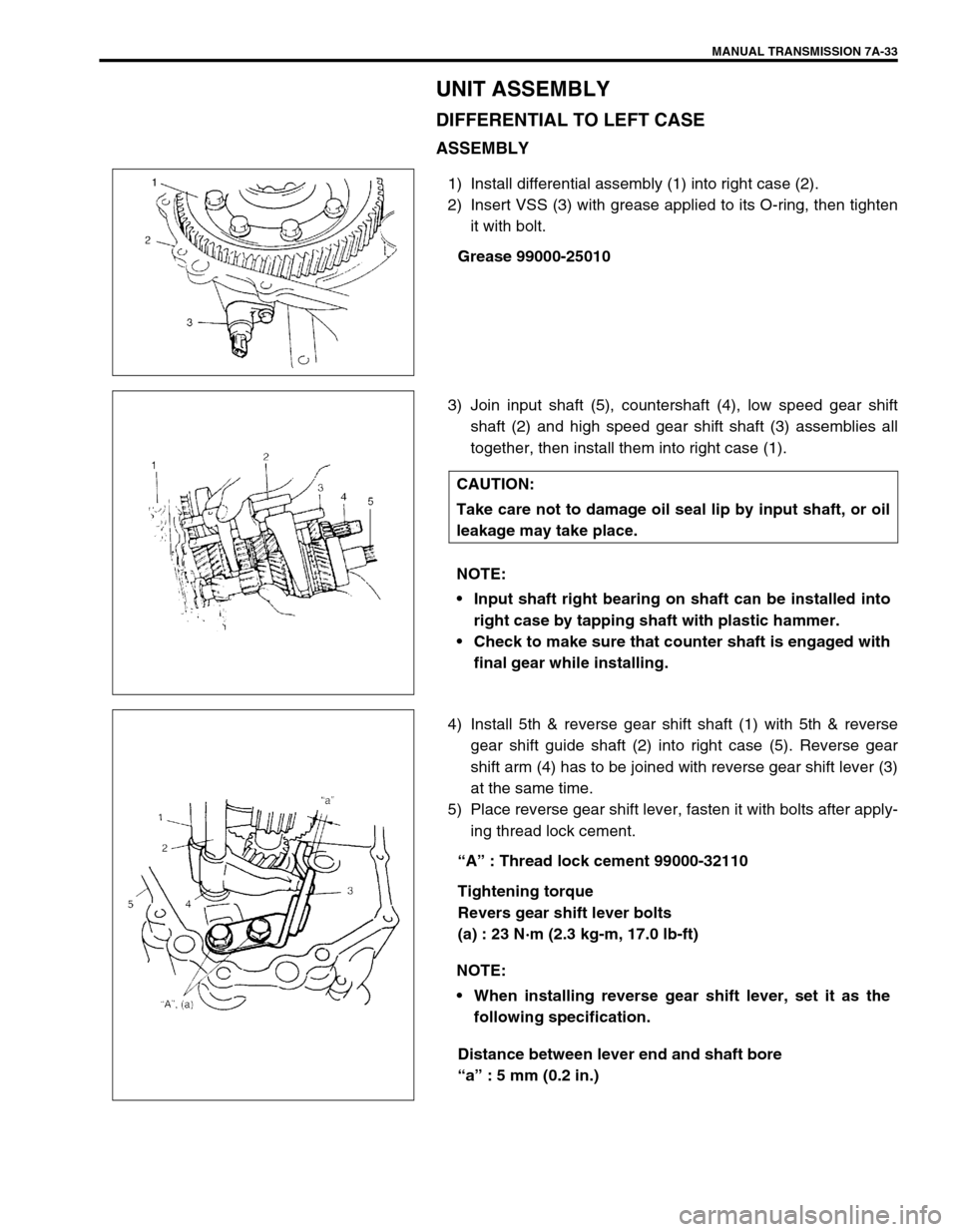
1) Install differential assembly (1) into right case (2).
2) Insert VSS (3) with grease applied to its O-ring, then tighten
it with bolt.
Grease 99000-25010
3) Join input shaft (5), countershaft (4), low speed gear shift
shaft (2) and high speed gear shift shaft (3) assemblies all
together, then install them into right case (1).
4) Install 5th & reverse gear shift shaft (1) with 5th & reverse
gear shift guide shaft (2) into right case (5). Reverse gear
shift arm (4) has to be joined with reverse gear shift lever (3)
at the same time.
5) Place reverse gear shift lever, fasten it with bolts after apply-
ing thread lock cement.
“A” : Thread lock cement 99000-32110
Tightening torque
Revers gear shift lever bolts
(a) : 23 N·m (2.3 kg-m, 17.0 lb-ft)
Distance between lever end and shaft bore
“a” : 5 mm (0.2 in.)
CAUTION:
Take care not to damage oil seal lip by input shaft, or oil
leakage may take place.
NOTE:
Input shaft right bearing on shaft can be installed into
right case by tapping shaft with plastic hammer.
Check to make sure that counter shaft is engaged with
final gear while installing.
NOTE:
When installing reverse gear shift lever, set it as the
following specification.
Page 37 of 447

MANUAL TRANSMISSION 7A-37
8) Install needle bearing of separated steel cage type to input
shaft, apply oil then install 5th gear (1) and special tool to
stop shaft rotation.
Special tool
(B) : 09927-76010
9) Install new countershaft nut (2) and tighten it to specification.
Tightening torque
Countershaft nut (b) : 60 N·m (6.0 kg-m, 43.5 lb-ft)
10) Remove special tool, then caulk nut at C with caulking tool
and hammer.
11) Install synchronizer ring (2).
12) Fit 5th gear shift fork (1) to sleeve & hub assembly (3) and
install them into input shaft, shift shaft and shift guide shaft at
once aligning hub oil groove A with shaft mark B.
13) Drive in spring pin facing its slit A outward.
14) If equipped, install steel ball, tighten shift fork plug (3) to
which thread lock cement have been applied.
“A” : Thread lock 1322 99000-32110
Tightening torque
5th shift fork plug (c) : 10 N·m (1.0 kg-m, 7.5 lb-ft)
15) Fit hub plate (1) and fix it with circlip (2).
16) If equipped, install circlip (4) to the end of 5th & reverse gear
shift guide shaft.
NOTE:
Long flange of hub faces inward (gear side).
A : Oil groove (Align with B)
B : Punch mark
C : Caulking
CAUTION:
Coat shift fork plug with thread lock cement reason-
ably. If it is done to much, excess may interfere in ball
movement and cause hard shift to 5th speed.
Make sure circlip is installed in shaft groove securely.
A : Pin slit (Face outward)
Page 39 of 447
MANUAL TRANSMISSION 7A-39
6) Tighten backup lamp switch (1) to specified torque.
Tightening torque
Backup lamp switch (b) : 19 N·m (1.9 kg-m, 14.0 lb-ft)
7) Check input shaft for rotation in each gear position.
8) Also confirm function of back up light switch in reverse posi-
tion by using ohmmeter.
TIGHTENING TORQUE SPECIFICATION
Fastening partTightening torque
Nm kg-m lb-ft
Transmission oil level/filler and drain plugs 21 2.1 15.5
Oil gutter bolt 10 1.0 7.5
Final gear bolts 90 9.0 65.0
Reverse gear shift lever bolts 23 2.3 17.0
Transmission case bolts 19 1.9 14.0
Reverse shaft bolt 23 2.3 17.0
Locating spring bolts 13 1.3 9.5
Left case plate screw 9 0.9 6.5
Countershaft nut 60 6.0 43.5
5th shift fork plug 10 1.0 7.5
Side cover No.1 bolts 10 1.0 7.5
Side cover No.2 bolts 23 2.3 17.0
Guide case bolts 23 2.3 17.0
Gear shift interlock bolt 23 2.3 17.0
5th to reverse interlock guide bolt 23 2.3 17.0
Backup lamp switch 19 1.9 14.0
Page 40 of 447
7A-40 MANUAL TRANSMISSION
REQUIRED SERVICE MATERIAL
SPECIAL TOOL
MaterialRecommended SUZUKI product
(Part Number)Use
Lithium grease SUZUKI SUPER GREASE A
(99000-25010) Oil seal lips
O-rings
Select lever boss
Select lever shaft bush
Gear shift control cable end
Sealant SUZUKI BOND NO.1215
(99000-31110) Oil drain plug and filler/level plug
Locating spring bolts
Mating surface of transmission case
Mating surface of side cover
Gear shift interlock bolt
5th to reverse interlock guide bolt
Thread lock cement THREAD LOCK 1322
(99000-32110) Reverse gear shift lever bolts
Oil gutter bolt
Shift fork plug
Reverse shaft bolt
Final gear bolts
09900-06107 09900-20606 09900-20701 09913-60910
Snap ring pliers
(Opening type)Dial gauge Magnetic stand Bearing puller
09913-75510 09913-80112 09913-84510 09922-85811
Bearing installer Bearing installer Bearing installer Spring pin remover
4.5 mm
Page 44 of 447

7B-2 AUTOMATIC TRANSMISSION (4 A/T)
DTC P0702/P1702 (DTC No.52)
TRANSMISSION CONTROL SYSTEM
ELECTRICAL OR INTERNAL
MALFUNCTION OF TCM ....................... 7B-52
INSPECTION OF TCM AND ITS
CIRCUITS ............................................... 7B-53
ON-VEHICLE SERVICE ................................. 7B-55
MAINTENANCE SERVICE ......................... 7B-55
FLUID LEVEL AT NORMAL OPERATING
TEMPERATURE ..................................... 7B-55
FLUID LEVEL AT ROOM
TEMPERATURE ..................................... 7B-56
FLUID CHANGE ..................................... 7B-56
SELECTOR LEVER .................................... 7B-57
TRANSMISSION RANGE SENSOR
(SHIFT SWITCH) ........................................ 7B-58
SELECTOR CABLE .................................... 7B-60
OUTPUT SHAFT SPEED SENSOR
(A/T VSS) .................................................... 7B-62
INPUT SHAFT SPEED SENSOR ............... 7B-63
VEHICLE SPEED SENSOR (VSS)............. 7B-63
THROTTLE POSITION SENSOR............... 7B-63
ENGINE COOLANT TEMP. (ECT)
SENSOR ..................................................... 7B-64
DROPPING RESISTOR ............................. 7B-64
O/D OFF SWITCH ...................................... 7B-65
SHIFT SOLENOID VALVES AND
TRANSMISSION TEMPERATURE
SENSOR ..................................................... 7B-65
SHIFT SOLENOID VALVES ................... 7B-66
TRANSMISSION TEMPERATURE
SENSOR ................................................. 7B-66
DIFFERENTIAL SIDE OIL SEAL ................ 7B-68TRANSMISSION CONTROL MODULE
(TCM).......................................................... 7B-69
LEARNING CONTROL INITIALIZATION 7B-70
BRAKE INTERLOCK SYSTEM
(IF EQUIPPED)........................................... 7B-70
KEY INTERLOCK CABLE
(IF EQUIPPED)........................................... 7B-72
TRANSMISSION UNIT REPAIR
OVERHAUL ................................................... 7B-75
DISMOUNTING .......................................... 7B-76
REMOUNTING ........................................... 7B-77
UNIT DISASSEMBLY ................................. 7B-78
DISASSEMBLY/ASSEMBLY OF
SUBASSEMBLY ......................................... 7B-88
OIL PUMP ............................................... 7B-88
FRONT CLUTCH (C2 CLUTCH) ............ 7B-91
REAR CLUTCH (C1 CLUTCH) ............... 7B-95
DIRECT CLUTCH (C0 CLUTCH) ......... 7B-100
PLANETARY SET................................. 7B-104
VALVE BODY ....................................... 7B-106
DIFFERENTIAL ASSEMBLY ................ 7B-112
REAR COVER (O/D BRAKE PISTON
ASSEMBLY) ......................................... 7B-115
PLANETARY SUN GEAR NO.1
ASSEMBLY .......................................... 7B-115
TORQUE CONVERTER HOUSING ..... 7B-116
TRANSMISSION CASE ........................ 7B-117
UNIT ASSEMBLY ..................................... 7B-118
TIGHTENING TORQUE SPECIFICATION .. 7B-136
SPECIAL TOOL ........................................... 7B-137
REQUIRED SERVICE MATERIAL .............. 7B-139
Page 45 of 447

AUTOMATIC TRANSMISSION (4 A/T) 7B-3
GENERAL DESCRIPTION
This automatic transmission is a full automatic type with 3-speed plus overdrive (O/D).
The torque converter is a 3-element, 1-step and 2-phase type equipped with lock-up mechanism. The gear shift
device consists of 2 sets of planetary gear units, sets of 3 disc type clutches, 3sets of disc type brakes and one-
way clutch. The gear shift is done by selecting one of 6 positions (“P”, “R”, “N”, “D”, “2” and “L”) by means of the
select lever installed on the floor. On the shift knob, there is an overdrive (O/D) cut switch which allows shift-up
to the overdrive mode and shift-down from the overdrive mode.
1. Final gear 6. Overdrive brake (B0) 11. Oil strainer 16. Front clutch (C2)
2. Differential gear assembly 7. Direct clutch (C0) 12. Counter drive gear (Reduction gear) 17. Reverse brake (B2)
3. Parking gear 8. Rear planetary gear 13. Oil pump 18. Rear clutch (C1)
4. Counter driven gear (Reduction gear) 9. Front planetary gear 14. Input shaft 19. Differential drive pinion shaft
5. 1st and 2nd brake (B1) 10. Valve body assembly 15. Torque converter