Page 177 of 447

AUTOMATIC TRANSMISSION (4 A/T) 7B-135
67) Install breather sensor hose (1).
68) Install transmission range sensor (2).
Install it temporarily so that the adjustment can be done after
installing assembly back to the vehicle.
Tightening torque
Transmission range sensor bolt
(a) : 18 N·m (1.8 kg-m, 13.0 lb-ft)
69) Install torque converter (1) to input shaft.
Install torque converter, using care not to damage oil seal of
oil pump.
After installing torque converter, check to make sure that dis-
tance “a” is within specification.
Torque converter installing position
“a” : More than 19.9 mm (0.783 in.)
Check torque converter for smooth rotation.
Apply grease around cup at the center of torque converter.
“C” : Grease 99000-25010
CAUTION:
Before installing converter, make sure that its pump
hub portion is free from nicks, burrs or damage which
may cause oil seal to leak.
Be very careful not to drop converter on oil pump gear.
Damage in gear, should it occur, may cause a critical
trouble.
2. Flange nut
3. Torque converter housing
4. Cup
Page 178 of 447

7B-136 AUTOMATIC TRANSMISSION (4 A/T)
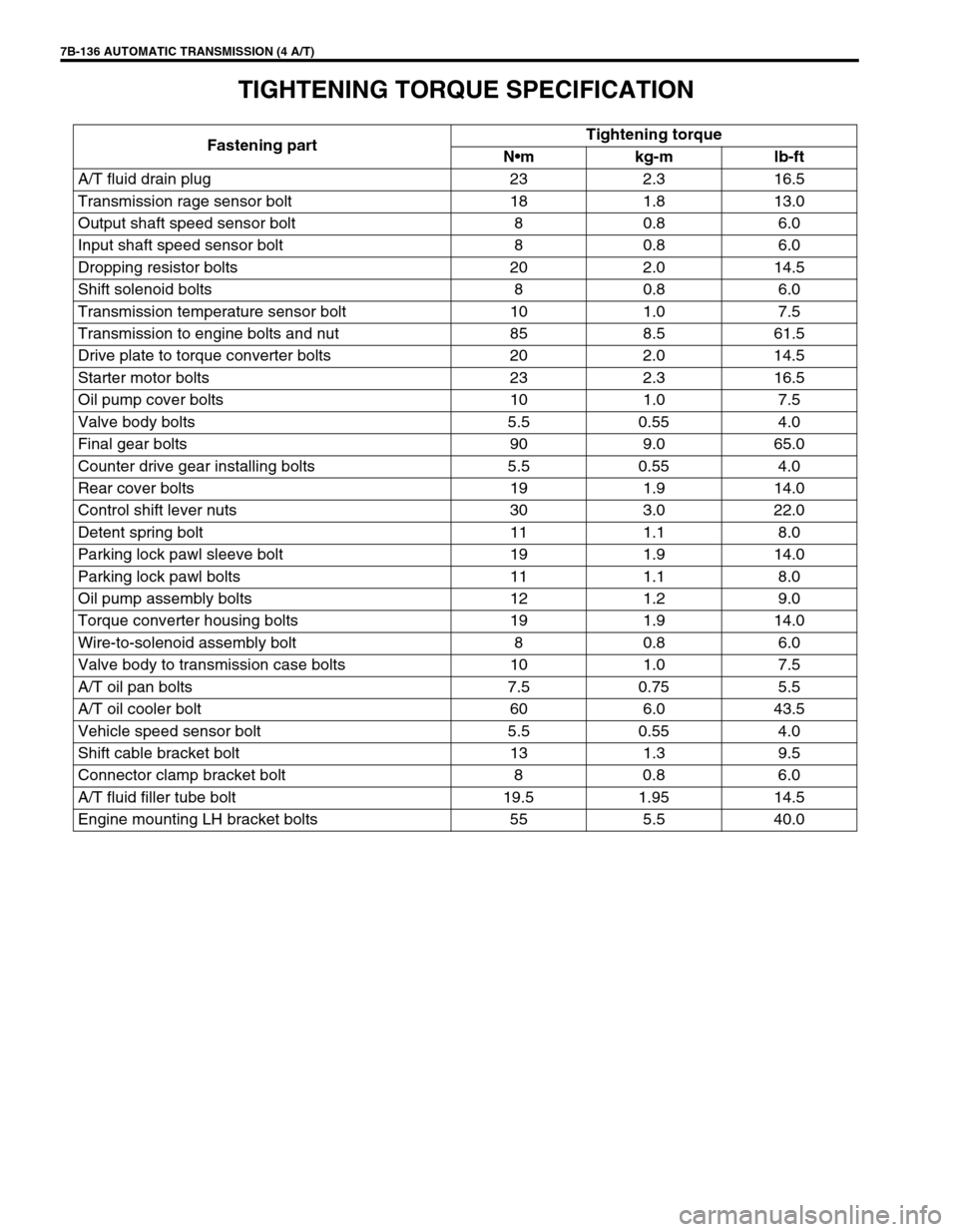
TIGHTENING TORQUE SPECIFICATION
Fastening partTightening torque
Nm kg-m lb-ft
A/T fluid drain plug 23 2.3 16.5
Transmission rage sensor bolt 18 1.8 13.0
Output shaft speed sensor bolt 8 0.8 6.0
Input shaft speed sensor bolt 8 0.8 6.0
Dropping resistor bolts 20 2.0 14.5
Shift solenoid bolts 8 0.8 6.0
Transmission temperature sensor bolt 10 1.0 7.5
Transmission to engine bolts and nut 85 8.5 61.5
Drive plate to torque converter bolts 20 2.0 14.5
Starter motor bolts 23 2.3 16.5
Oil pump cover bolts 10 1.0 7.5
Valve body bolts 5.5 0.55 4.0
Final gear bolts 90 9.0 65.0
Counter drive gear installing bolts 5.5 0.55 4.0
Rear cover bolts 19 1.9 14.0
Control shift lever nuts 30 3.0 22.0
Detent spring bolt 11 1.1 8.0
Parking lock pawl sleeve bolt 19 1.9 14.0
Parking lock pawl bolts 11 1.1 8.0
Oil pump assembly bolts 12 1.2 9.0
Torque converter housing bolts 19 1.9 14.0
Wire-to-solenoid assembly bolt 8 0.8 6.0
Valve body to transmission case bolts 10 1.0 7.5
A/T oil pan bolts 7.5 0.75 5.5
A/T oil cooler bolt 60 6.0 43.5
Vehicle speed sensor bolt 5.5 0.55 4.0
Shift cable bracket bolt 13 1.3 9.5
Connector clamp bracket bolt 8 0.8 6.0
A/T fluid filler tube bolt 19.5 1.95 14.5
Engine mounting LH bracket bolts 55 5.5 40.0
Page 179 of 447
AUTOMATIC TRANSMISSION (4 A/T) 7B-137
SPECIAL TOOL
09900-06108 09900-20606 09900-20701 09913-75510
Snap ring plier
(Closing type)Dial gauge Magnetic stand Bearing installer
09913-80112 09913-85210 9922-85811 09923-74510
Bearing installer Bearing installer Spring pin remover
(6 mm)Bearing remover
09924-74510 09925-37811-001 09925-88210 09926-26030
Installer handle Oil pressure gauge Bearing puller attachment Air installer No.1
09926-26040 09926-68310 09926-96010 09926-96020
Air installer No.2 Bearing installer Clutch spring compressor Clutch spring compressor
Page 180 of 447
7B-138 AUTOMATIC TRANSMISSION (4 A/T)
09926-96030 09926-96040 09930-30102 09931-76030
Clutch spring compressor
No.7Clutch spring compressor
No.8Sliding shaft 16/14 pin DLC adapter
09931-76011 09941-64511 09944-68510 09951-16060
Tech 1A kit
See NOTE below.Bearing remover Bearing installer Bush remover
09952-06010 09952-06020 09926-26050
Dial gauge plate No.1 Dial gauge plate No.2 Mass storage cartridge Air installer No.3
09940-53111
Oil seal install tool
Page 181 of 447
AUTOMATIC TRANSMISSION (4 A/T) 7B-139
REQUIRED SERVICE MATERIAL
NOTE:
This kit includes the following items.
1. Storage case, 2. Operator’s manual, 3. SUZUKI scan tool (Tech-1A), 4. DLC cable,
5. Test lead / probe, 6. Power source cable, 7. DLC cable adaptor, 8. Self-test adaptor
MaterialRecommended SUZUKI product
(Part Number)Use
Automatic transmission fluid
An equivalent of DEXRON
®-III or
DEXRONR
®-IIEAutomatic transmission
Parts lubrication when installing
Sealant SUZUKI BOND No. 1215
(99000-31110)Case housing star-shaped recess
bolts
(3 pcs only)
Lithium grease SUZUKI SUPER GREASE C
(99000-25030)Retaining parts in place when
assembling
Oil seal lips
D-rings
O-rings
SUZUKI SUPER GREASE A
(99000-25010)Cable ends
Converter center cup
Thread lock cement THREAD LOCK 1322
(99000-32110)Final gear bolts
Torque converter housing bolts
Page 182 of 447
7B-140 AUTOMATIC TRANSMISSION (4 A/T)
Page 184 of 447

7C-2 CLUTCH
GENERAL DESCRIPTION
The clutch is a diaphragm-spring clutch of a dry single disc type. The diaphragm spring is of a tapering-finger
type, which is a solid ring in the outer diameter part, with a series of tapered fingers pointing inward.
The disc, carrying four torsional coil springs, is positioned on the transmission input shaft with an involute spline
fit.
The clutch cover is secured to the flywheel, and carries the diaphragm spring in such a way that the peripheral
edge part of the spring pushes on the pressure plate against the flywheel (with the disc in between), when the
clutch release bearing is held back. This is the engaged condition of the clutch.
Depressing the clutch pedal causes the release bearing to advance and pushes on the tips of the tapered fin-
gers of the diaphragm spring. When this happens, the diaphragm spring pulls the pressure plate away from the
flywheel, thereby interrupting the flow of drive from flywheel through clutch disc to transmission input shaft.
1. Crankshaft 6. Diaphragm spring
2. Flywheel 7. Release bearing
3. Clutch disc 8. Input shaft bearing
4. Pressure plate 9. Input shaft
5. Clutch cover 10. Release shaft
Page 185 of 447

CLUTCH 7C-3
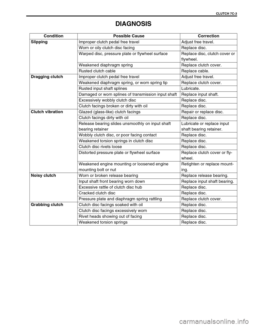
DIAGNOSIS
Condition Possible Cause Correction
Slipping
Improper clutch pedal free travel Adjust free travel.
Worn or oily clutch disc facing Replace disc.
Warped disc, pressure plate or flywheel surface Replace disc, clutch cover or
flywheel.
Weakened diaphragm spring Replace clutch cover.
Rusted clutch cable Replace cable.
Dragging clutch
Improper clutch pedal free travel Adjust free travel.
Weakened diaphragm spring, or worn spring tip Replace clutch cover.
Rusted input shaft splines Lubricate.
Damaged or worn splines of transmission input shaft Replace input shaft.
Excessively wobbly clutch disc Replace disc.
Clutch facings broken or dirty with oil Replace disc.
Clutch vibration
Glazed (glass-like) clutch facings Repair or replace disc.
Clutch facings dirty with oil Replace disc.
Release bearing slides unsmoothly on input shaft
bearing retainerLubricate or replace input
shaft bearing retainer.
Wobbly clutch disc, or poor facing contact Replace disc.
Weakened torsion springs in clutch disc Replace disc.
Clutch disc rivets loose Replace disc.
Distorted pressure plate or flywheel surface Replace clutch cover or fly-
wheel.
Weakened engine mounting or loosened engine
mounting bolt or nutRetighten or replace mount-
ing.
Noisy clutch
Worn or broken release bearing Replace release bearing.
Input shaft front bearing worn down Replace input shaft bearing.
Excessive rattle of clutch disc hub Replace disc.
Cracked clutch disc Replace disc.
Pressure plate and diaphragm spring rattling Replace clutch cover.
Grabbing clutch
Clutch disc facings soaked with oil Replace disc.
Clutch disc facings excessively worn Replace disc.
Rivet heads showing out of facing Replace disc.
Weakened torsion springs Replace disc.