Page 190 of 447
7C-8 CLUTCH
UNIT REPAIR OVERHAUL
CLUTCH COVER, CLUTCH DISC AND FLYWHEEL
REMOVAL
1) Dismount transmission assembly referring to Section 7A.
2) Hold flywheel stationary with special tool (A) and remove
clutch cover bolts (1), clutch cover (2) and clutch disc.
Special tool
(A) : 09924-17810
1. Flywheel7. Release bearing
: Apply grease 99000-25010 to joint of bearing and release
shaft and also bearing inside. (0.3 g)
2. Clutch release shaft seal
: Apply grease 99000-25010 to seal lip. (0.3 g)8. Clutch cover
3. Clutch release shaft No.2 bush
: Apply grease 99000-25010 to bush inside. (0.3 g)9. Clutch disc
4. Return spring 10. Clutch cover bolt
5. Clutch release shaft
Apply grease 99000-25010 to the end of release shaft arm. (0.3 g)Tightening torque
6. Clutch release shaft No.1 bush
: Apply grease 99000-25010 to bush inside. (0.3 g)Do not reuse.
Page 193 of 447
CLUTCH 7C-11
4) Slightly apply grease to input shaft (1), then join transmission
assembly with engine. Refer to Section 7A for remounting
procedure.
“A” : Grease, 99000-25210
CLUTCH RELEASE SYSTEM
REMOVAL
1) Remove release lever by loosening its bolt.
2) Take out release bearing by turning release shaft (1).
3) Unhook return spring by using pliers.
4) Drive out No.2 bush by using special tool and hammer.
Release shaft seal will also be pushed out.
Special tool
(A) : 09922-46010
5) Remove release shaft and return spring.
6) Install tap (M16 X 1.5) (1) to clutch release shaft No.1 bush.
7) Pull out No.1 bush by using tap (1) and special tools.
Special tool
(B) : 09923-46020
(C) : 09930-30104 NOTE:
When inserting transmission input shaft to clutch disc,
turn crankshaft little by little to match splines.
Page 203 of 447
TRANSFER 7D-5
UNIT DISMOUNTING
1) Disconnect negative cable at battery.
2) Hoist vehicle and remove wheels.
3) Drain transmission oil.
4) Remove exhaust No.1 pipe (1).
5) Remove propeller shaft.
6) Remove right side drive shaft (1) refer to Section 4A.
7) Remove Stiffener (3).
8) With transmission assembly held on jack, remove rear
mounting bolts (1).
9) Remove transfer mounting bolts and draw out transfer
assembly from transmission assembly.
2. Exhaust No.2 pipe
12
1
1. Transfer
2. Transmission
1
Page 218 of 447

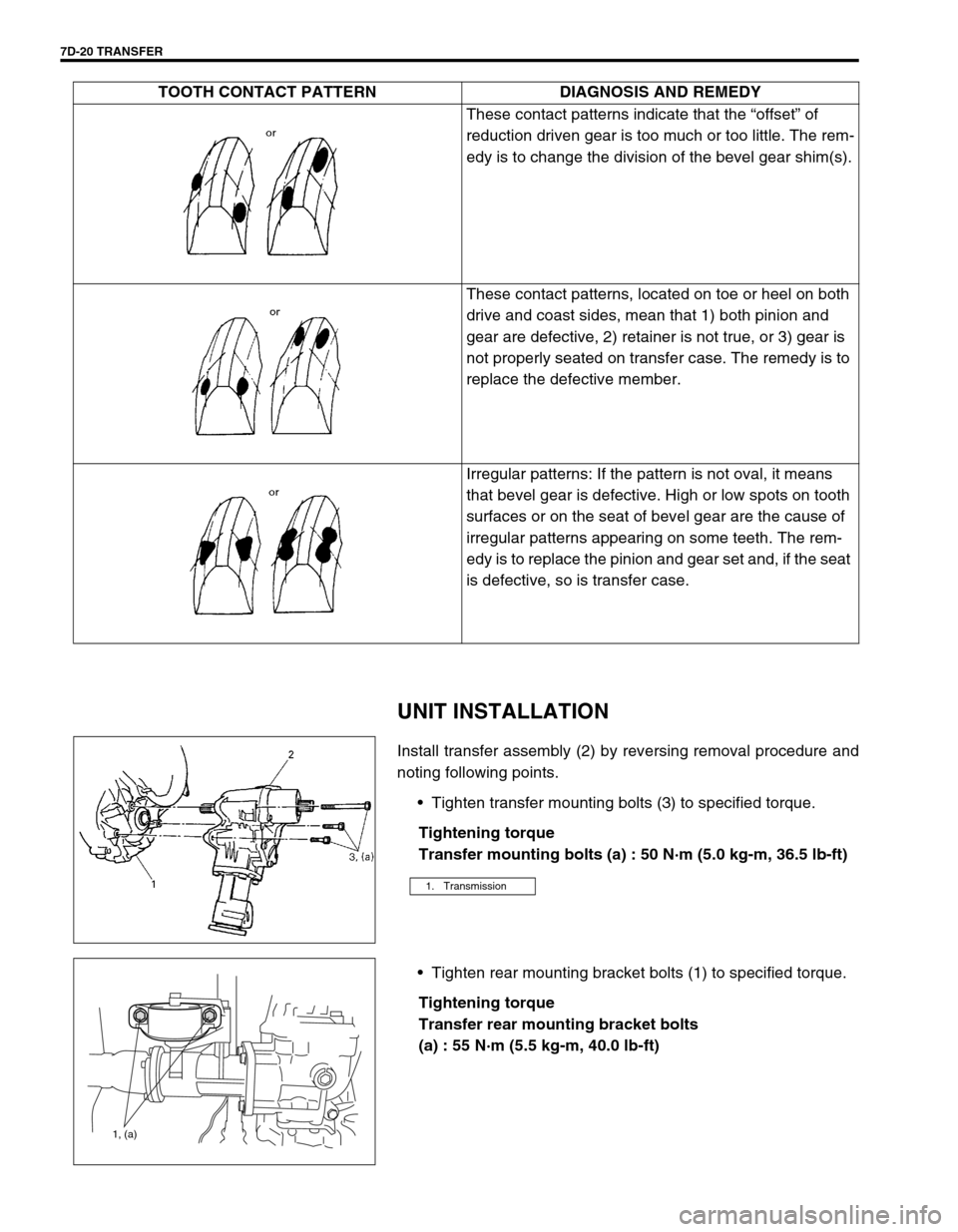
7D-20 TRANSFER
UNIT INSTALLATION
Install transfer assembly (2) by reversing removal procedure and
noting following points.
Tighten transfer mounting bolts (3) to specified torque.
Tightening torque
Transfer mounting bolts (a) : 50 N·m (5.0 kg-m, 36.5 lb-ft)
Tighten rear mounting bracket bolts (1) to specified torque.
Tightening torque
Transfer rear mounting bracket bolts
(a) : 55 N·m (5.5 kg-m, 40.0 lb-ft)These contact patterns indicate that the “offset” of
reduction driven gear is too much or too little. The rem-
edy is to change the division of the bevel gear shim(s).
These contact patterns, located on toe or heel on both
drive and coast sides, mean that 1) both pinion and
gear are defective, 2) retainer is not true, or 3) gear is
not properly seated on transfer case. The remedy is to
replace the defective member.
Irregular patterns: If the pattern is not oval, it means
that bevel gear is defective. High or low spots on tooth
surfaces or on the seat of bevel gear are the cause of
irregular patterns appearing on some teeth. The rem-
edy is to replace the pinion and gear set and, if the seat
is defective, so is transfer case. TOOTH CONTACT PATTERN DIAGNOSIS AND REMEDY
1. Transmission
1, (a)
Page 219 of 447
TRANSFER 7D-21
Tighten mounting bolt and mounting bracket bolts and nuts
to specified torque.
Tightening torque
Transfer rear mounting bracket nuts
(a) : 50 N·m (5.0 kg-m, 36.5 lb-ft)
Transfer mounting bolt
(b) : 55 N·m (5.5 kg-m, 40.0 lb-ft)
Transfer rear mounting bracket No.2 bolts
(c) : 55 N·m (5.5 kg-m, 40.0 lb-ft)
Tighten transfer stiffener bolts (4) to specified torque.
Tightening torque
Transfer stiffener bolts (a) : 50 N·m (5.0 kg-m, 36.5 lb-ft)
Tighten exhaust pipe bolts.
Tightening torque
Exhaust pipe bolts
(a) : 50 N·m (5.0 kg-m, 36.5 lb-ft)
Install right side drive shaft, refer to Section 4A.
Install propeller shaft and tighten propeller shaft bolts and
center support bolts to specified torque (refer to Section 4B).
Fill gear oil to transfer as specified, refer to OIL CHANGE of
ON-VEHICLE SERVICE.
Check oil level and leakage.
(a)
(b)
(c)
1. Transmission
2. Transfer
3. Stiffener
1. Exhaust No.1 pipe
2. Exhaust No.2 pipe
1
(a)(a)2