2000 SUZUKI SWIFT brake fluid
[x] Cancel search: brake fluidPage 129 of 447

AUTOMATIC TRANSMISSION (4 A/T) 7B-87
INSPECTION
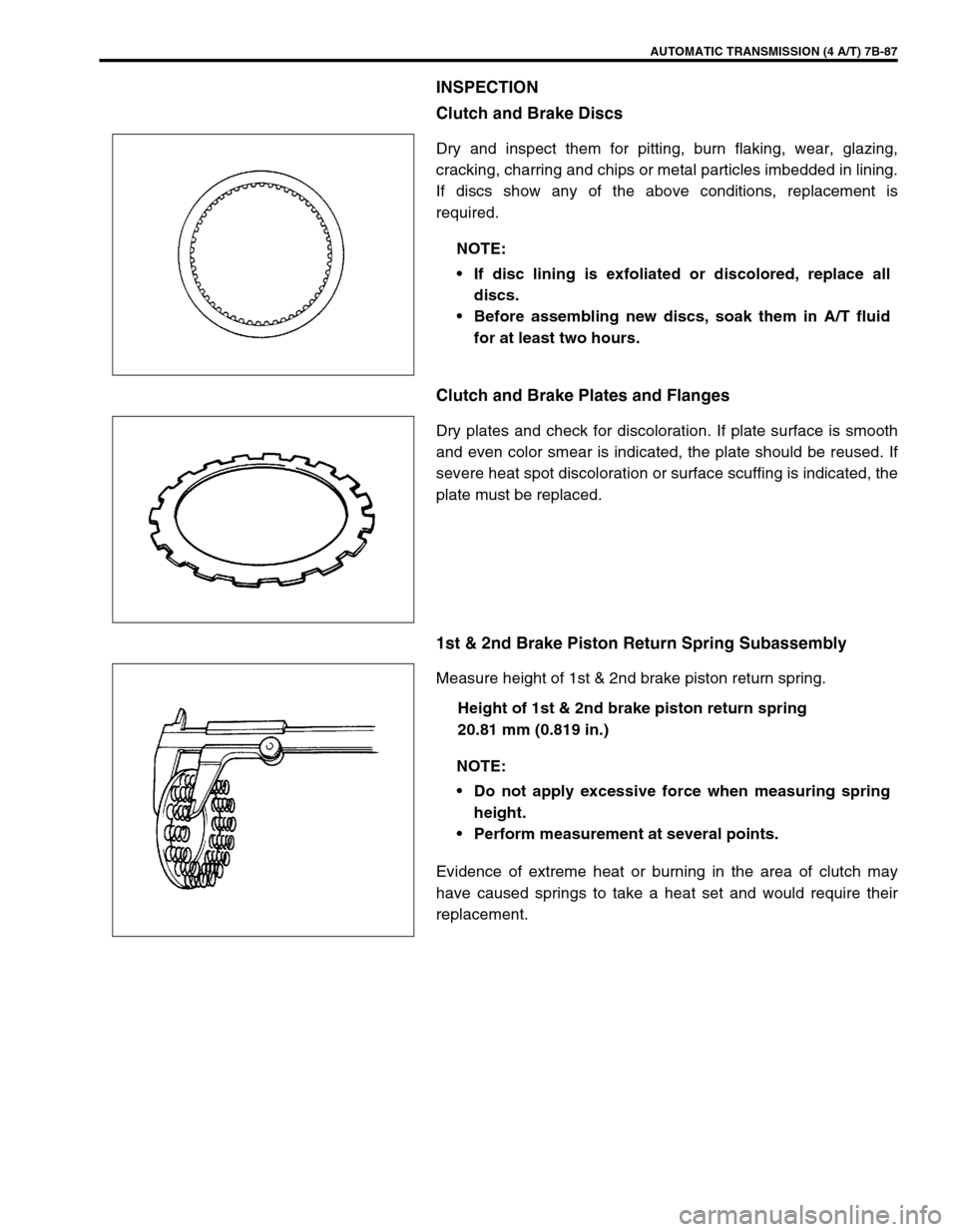
Clutch and Brake Discs
Dry and inspect them for pitting, burn flaking, wear, glazing,
cracking, charring and chips or metal particles imbedded in lining.
If discs show any of the above conditions, replacement is
required.
Clutch and Brake Plates and Flanges
Dry plates and check for discoloration. If plate surface is smooth
and even color smear is indicated, the plate should be reused. If
severe heat spot discoloration or surface scuffing is indicated, the
plate must be replaced.
1st & 2nd Brake Piston Return Spring Subassembly
Measure height of 1st & 2nd brake piston return spring.
Height of 1st & 2nd brake piston return spring
20.81 mm (0.819 in.)
Evidence of extreme heat or burning in the area of clutch may
have caused springs to take a heat set and would require their
replacement.NOTE:
If disc lining is exfoliated or discolored, replace all
discs.
Before assembling new discs, soak them in A/T fluid
for at least two hours.
NOTE:
Do not apply excessive force when measuring spring
height.
Perform measurement at several points.
Page 130 of 447

7B-88 AUTOMATIC TRANSMISSION (4 A/T)
DISASSEMBLY/ASSEMBLY OF SUBASSEMBLY
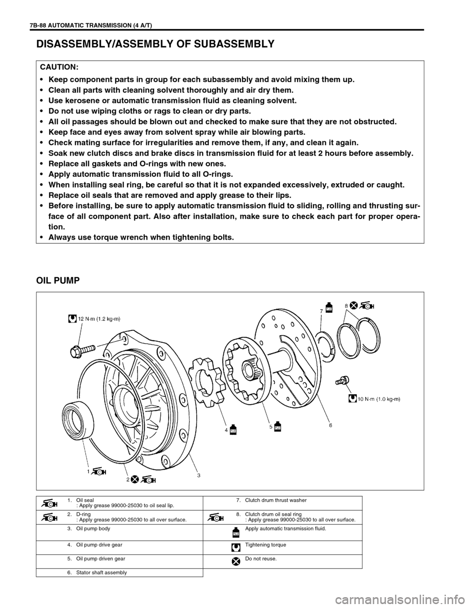
OIL PUMP
CAUTION:
Keep component parts in group for each subassembly and avoid mixing them up.
Clean all parts with cleaning solvent thoroughly and air dry them.
Use kerosene or automatic transmission fluid as cleaning solvent.
Do not use wiping cloths or rags to clean or dry parts.
All oil passages should be blown out and checked to make sure that they are not obstructed.
Keep face and eyes away from solvent spray while air blowing parts.
Check mating surface for irregularities and remove them, if any, and clean it again.
Soak new clutch discs and brake discs in transmission fluid for at least 2 hours before assembly.
Replace all gaskets and O-rings with new ones.
Apply automatic transmission fluid to all O-rings.
When installing seal ring, be careful so that it is not expanded excessively, extruded or caught.
Replace oil seals that are removed and apply grease to their lips.
Before installing, be sure to apply automatic transmission fluid to sliding, rolling and thrusting sur-
face of all component part. Also after installation, make sure to check each part for proper opera-
tion.
Always use torque wrench when tightening bolts.
1. Oil seal
: Apply grease 99000-25030 to oil seal lip.7. Clutch drum thrust washer
2. D-ring
: Apply grease 99000-25030 to all over surface. 8. Clutch drum oil seal ring
: Apply grease 99000-25030 to all over surface.
3. Oil pump body Apply automatic transmission fluid.
4. Oil pump drive gear Tightening torque
5. Oil pump driven gear Do not reuse.
6. Stator shaft assembly
Page 160 of 447

7B-118 AUTOMATIC TRANSMISSION (4 A/T)
2) Install new oil seal to transmission case.
Use special tool to press-fit oil seal until oil seal end face is
flush with transmission case end face.
Special tool
(F) : 09913-75510
UNIT ASSEMBLY
CAUTION:
Automatic transmission consists of highly precise parts. As even a flaw in a small part may cause
oil leakage or decrease in function, check each part carefully before installation.
Clean all parts with compressed air. Never use wiping cloths or rags.
Before assembling new clutch discs and brake band, soak them in automatic transmission fluid for
at least 2 hours.
Be sure to use new gaskets and O-rings.
Lubricate O-rings with automatic transmission fluid.
Apply automatic transmission fluid on sliding or rotating surfaces of the parts before assembly.
Use yellow petrolatum grease or Suzuki Super Grease C to retain parts in place.
Be sure to install thrust bearings and races in correct direction and position.
Make sure that snap ring ends are not aligned with one of cutouts and are installed in groove cor-
rectly.
Do not use adhesive cements on gaskets and similar parts.
Be sure to torque each bolt and nut to specification.
Page 246 of 447

8-2 BODY ELECTRICAL SYSTEM
CIRCUIT.................................................... 8-15
FUEL METER AND FUEL LEVEL
SENSOR (GAUGE UNIT) ............................. 8-16
FUEL LEVEL METER ............................... 8-16
FUEL LEVEL SENSOR (GAUGE UNIT) ... 8-17
SPEED METER AND VSS ........................... 8-17
VSS ........................................................... 8-17
ENGINE COOLANT TEMPERATURE (ECT)
METER AND SENSOR................................. 8-17
ENGINE COOLANT TEMPERATURE
(ECT) METER ........................................... 8-17
ECT SENSOR ........................................... 8-18
OIL PRESSURE WARNING LIGHT ............. 8-18
OIL PRESSURE SWITCH ........................ 8-18
BRAKE FLUID LEVEL AND PARKING
BRAKE WARNING LIGHT ............................ 8-18
BRAKE FLUID LEVEL SWITCH ............... 8-18
PARKING BRAKE SWITCH...................... 8-19
REAR WINDOW DEFOGGER...................... 8-19
DEFOGGER SWITCH .............................. 8-19
DEFOGGER WIRE ................................... 8-19
WIPERS AND WASHERS ............................ 8-21
COMPONENTS ........................................ 8-21
FRONT WIPER AND WASHER
SWITCH .................................................... 8-21
FRONT WIPER MOTOR........................... 8-23
WASHER TANK AND WASHER
PUMP ........................................................ 8-24
REAR WIPER AND WASHER SWITCH
(IF EQUIPPED) ......................................... 8-25REAR WIPER MOTOR .............................. 8-25
IGNITION KEY REMAINDER (IF EQUIPPED)
AND LIGHT REMAINDER WARNING
BUZZER ........................................................ 8-25
POWER WINDOW CONTROL SYSTEM
(IF EQUIPPED).............................................. 8-26
POWER WINDOW MAIN SWITCH ........... 8-26
POWER WINDOW SUB SWITCH ............. 8-27
DOOR SWITCH ............................................. 8-27
STOP LAMP (BRAKE) SWITCH ................... 8-27
POWER DOOR LOCK SYSTEM (IF
EQUIPPED) ................................................... 8-28
DOOR LOCK CONTROLLER .................... 8-28
DRIVER’S DOOR KNOB SWITCH ............ 8-28
DOOR LOCK ACTUATOR......................... 8-29
KEYLESS ENTRY SYSTEM (IF
EQUIPPED) ................................................... 8-29
DOOR LOCK CONTROLLER .................... 8-29
DOOR LOCK ACTUATOR......................... 8-29
RECEIVER................................................. 8-30
TRANSMITTER ......................................... 8-30
POWER DOOR MIRROR CONTROL
SYSTEM (IF EQUIPPED) .............................. 8-31
MIRROR SWITCH ..................................... 8-31
DOOR MIRROR ACTUATOR .................... 8-32
FRONT SEAT HEATER (IF EQUIPPED) ...... 8-32
SEAT HEATER SWITCH (DRIVER AND
PASSENGER SIDE) .................................. 8-32
SEAT HEATER WIRE................................ 8-33
Page 250 of 447

8-6 BODY ELECTRICAL SYSTEM
BRAKE AND PARKING BRAKE WARNING LIGHT
REAR WINDOW DEFOGGER
WIPERS AND WASHERS
FRONT WIPER AND WASHER
REAR WIPER AND WASHER (IF EQUIPPED)
Condition Possible Cause Correction
Brake warning light
does not light up
(when fluid low level
and/or parking brake
pull up)Bulb in combination meter blown Replace bulb.
Printed plate in combination meter faulty Check printed plate.
“IG/METER” fuse blown Replace fuse to check for short.
Brake fluid level switch faulty Check brake fluid level switch.
Parking brake switch faulty Check parking brake switch.
Wiring or grounding faulty Repair circuit.
Brake warning light
does not light up
when cranking (when
turned ignition switch
to ST position)Ignition switch faulty Check ignition switch.
Printed plate in combination meter faulty Check printed plate.
Wiring or grounding faulty Repair circuit.
Brake warning light
stay onBrake fluid level switch and/or parking brake
switch faultyCheck switch.
Condition Possible Cause Correction
Defogger does not
operate“REAR DEFG” fuse blown Replace fuse to check for short.
Heat wire faulty Repair heat wire.
Rear window defogger switch faulty Check switch.
Wiring or grounding faulty Repair circuit.
Condition Possible Cause Correction
Wiper malfunctions
“WIPER/WASHER” fuse blown Replace fuse to check for short.
Wiper motor faulty Check wiper motor.
Combination switch (wiper switch) faulty Check wiper switch.
Wiring or grounding faulty Repair circuit.
Washer malfunctions
Washer hose or nozzle clogged Clean or repair clogged hose or
nozzle.
“WIPER/WASHER” fuse blown Replace fuse to check for short.
Washer motor faulty Check washer motor.
Combination switch (wiper switch) faulty Check wiper switch.
Wiring or grounding faulty Repair circuit.
Page 259 of 447

BODY ELECTRICAL SYSTEM 8-15
COMBINATION METER
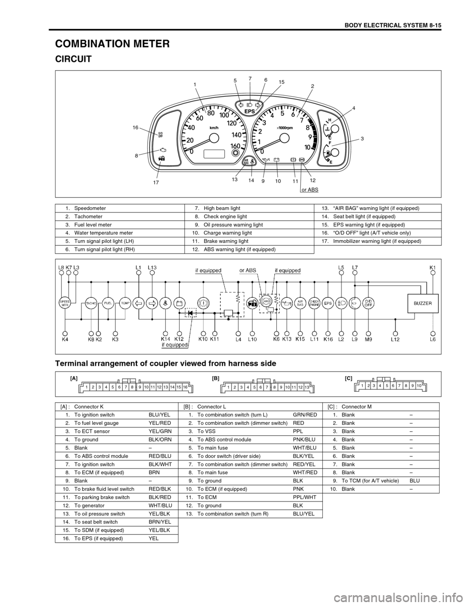
CIRCUIT
Terminal arrangement of coupler viewed from harness side
12
3 4
56 7
8
910
1112 13
14
1715
16
or ABS
1. Speedometer 7. High beam light 13.“AIR BAG” warning light (if equipped)
2. Tachometer 8. Check engine light 14. Seat belt light (if equipped)
3. Fuel level meter 9. Oil pressure warning light 15. EPS warning light (if equipped)
4. Water temperature meter 10. Charge warning light 16.“O/D OFF” light (A/T vehicle only)
5. Turn signal pilot light (LH) 11. Brake warning light 17. Immobilizer warning light (if equipped)
6. Turn signal pilot light (RH) 12. ABS warning light (if equipped)
[A] : Connector K [B] : Connector L [C] : Connector M
1. To ignition switch BLU/YEL 1. To combination switch (turn L) GRN/RED 1. Blank–
2. To fuel level gauge YEL/RED 2. To combination switch (dimmer switch) RED 2. Blank–
3. To ECT sensor YEL/GRN 3. To VSS PPL 3. Blank–
4. To ground BLK/ORN 4. To ABS control module PNK/BLU 4. Blank–
5. Blank–5. To main fuse WHT/BLU 5. Blank–
6. To ABS control module RED/BLU 6. To door switch (driver side) BLK/YEL 6. Blank–
7. To ignition switch BLK/WHT 7. To combination switch (dimmer switch) RED/YEL 7. Blank–
8. To ECM (if equipped) BRN 8. To main fuse WHT/RED 8. Blank–
9. Blank–9. To ground BLK 9. To TCM (for A/T vehicle) BLU
10. To brake fluid level switch RED/BLK 10. To ECM (if equipped) PNK 10. Blank–
11. To parking brake switch BLK/RED 11. To ECM PPL/WHT
12. To generator WHT/BLU 12. To ground BLK
13. To oil pressure switch YEL/BLK 13. To combination switch (turn R) BLU/YEL
14. To seat belt switch BRN/YEL
15. To SDM (if equipped) YEL/BLK
16. To EPS (if equipped) YEL
1 2 3 4 5 6 7 8 9 10 11 12 13 14 15 161 2 3 4 5 6 7 8 9 10 11 12 131234 567 8910[A] [B] [C]
Page 262 of 447

8-18 BODY ELECTRICAL SYSTEM
ECT SENSOR
REMOVAL, INSTALLATION AND INSPECTION
Refer to “ECT SENSOR” in Section 6E1.
OIL PRESSURE WARNING LIGHT
OIL PRESSURE SWITCH
ON-VEHICLE INSPECTION
1) Disconnect oil pressure switch (1) lead wire.
2) Check for continuity between oil pressure switch terminal (2)
and cylinder block (3) as shown in figure.
If not, replace oil pressure switch (1).
Oil pressure switch specification
During engine running : No continuity
At engine stop : Continuity
REMOVAL AND INSTALLATION
Refer to “OIL PRESSURE CHECK” in Section 6A1.
BRAKE FLUID LEVEL AND PARKING BRAKE
WARNING LIGHT
BRAKE FLUID LEVEL SWITCH
INSPECTION
Check for continuity between terminals of brake fluid level switch
coupler.
If found defective, replace switch.
Brake fluid level switch specification
OFF position (float up) : No continuity
ON position (float down) : Continuity