Page 67 of 447
![SUZUKI SWIFT 2000 1.G Transmission Service Workshop Manual AUTOMATIC TRANSMISSION (4 A/T) 7B-25
[INTERMITTENT TROUBLES] and [NOTES ON SYSTEM CIR-
CUIT INSPECTION]
Refer to Section 0A.
DTC CHECK
[Check DTC with SUZUKI scan tool]
1) Turn ignition switch OFF.
2) SUZUKI SWIFT 2000 1.G Transmission Service Workshop Manual AUTOMATIC TRANSMISSION (4 A/T) 7B-25
[INTERMITTENT TROUBLES] and [NOTES ON SYSTEM CIR-
CUIT INSPECTION]
Refer to Section 0A.
DTC CHECK
[Check DTC with SUZUKI scan tool]
1) Turn ignition switch OFF.
2)](/manual-img/20/7605/w960_7605-66.png)
AUTOMATIC TRANSMISSION (4 A/T) 7B-25
[INTERMITTENT TROUBLES] and [NOTES ON SYSTEM CIR-
CUIT INSPECTION]
Refer to Section 0A.
DTC CHECK
[Check DTC with SUZUKI scan tool]
1) Turn ignition switch OFF.
2) After setting cartridge, connect SUZUKI scan tool to data link
connector (DLC) (1) located on underside of instrument
panel at driver’s seat side.
Special tool
(A) : 09931-76011 (SUZUKI scan tool)
(B) : Mass storage cartridge
(C) : 09931-76030 (16/14 pin DLC cable)
3) Turn ignition switch ON.
4) Read DTC according to instructions displayed on SUZUKI
scan tool and print it or write it down. Refer to SUZUKI scan
tool operator’s manual for further details.
5) After completing the check, turn ignition switch OFF and dis-
connect SUZUKI scan tool from data link connector (DLC)
(1).
[Check DTC without SUZUKI scan tool]
1) Turn ignition switch ON and make sure that O/D OFF lamp is
OFF in combination meter (O/D off switch OFF).
2) Turn ignition switch OFF.
3) Pull out clip (3) and remove glove box (2) from instrument
panel (1).
Page 95 of 447

AUTOMATIC TRANSMISSION (4 A/T) 7B-53
INSPECTION OF TCM AND ITS CIRCUITS
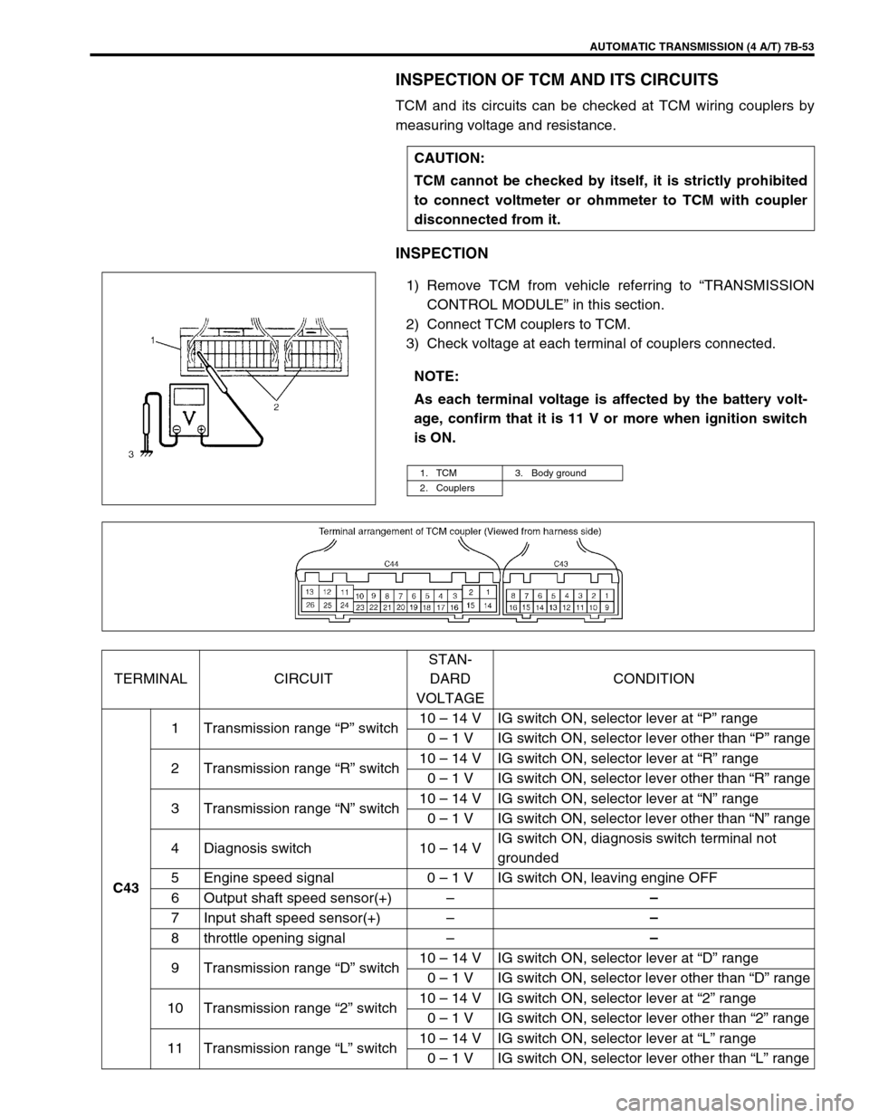
TCM and its circuits can be checked at TCM wiring couplers by
measuring voltage and resistance.
INSPECTION
1) Remove TCM from vehicle referring to “TRANSMISSION
CONTROL MODULE” in this section.
2) Connect TCM couplers to TCM.
3) Check voltage at each terminal of couplers connected.CAUTION:
TCM cannot be checked by itself, it is strictly prohibited
to connect voltmeter or ohmmeter to TCM with coupler
disconnected from it.
NOTE:
As each terminal voltage is affected by the battery volt-
age, confirm that it is 11 V or more when ignition switch
is ON.
1. TCM 3. Body ground
2. Couplers
TERMINAL CIRCUITSTAN-
DARD
VOLTAGECONDITION
C431 Transmission range “P” switch10 – 14 V IG switch ON, selector lever at “P” range
0 – 1 V IG switch ON, selector lever other than “P” range
2 Transmission range “R” switch10 – 14 V IG switch ON, selector lever at “R” range
0 – 1 V IG switch ON, selector lever other than “R” range
3 Transmission range “N” switch10 – 14 V IG switch ON, selector lever at “N” range
0 – 1 V IG switch ON, selector lever other than “N” range
4 Diagnosis switch 10 – 14 VIG switch ON, diagnosis switch terminal not
grounded
5 Engine speed signal 0 – 1 V IG switch ON, leaving engine OFF
6 Output shaft speed sensor(+)––
7 Input shaft speed sensor(+)––
8 throttle opening signal––
9 Transmission range “D” switch10 – 14 V IG switch ON, selector lever at “D” range
0 – 1 V IG switch ON, selector lever other than “D” range
10 Transmission range “2” switch10 – 14 V IG switch ON, selector lever at “2” range
0 – 1 V IG switch ON, selector lever other than “2” range
11 Transmission range “L” switch10 – 14 V IG switch ON, selector lever at “L” range
0 – 1 V IG switch ON, selector lever other than “L” range
Page 121 of 447
AUTOMATIC TRANSMISSION (4 A/T) 7B-79
4) Remove output shaft speed sensor (1) and input shaft speed
sensor (2).
5) Remove transmission range sensor (3).
6) Remove dropping resistor (4).
7) Remove breather hose (5).
8) Remove A/T fluid level gauge (1) and filler tube (2).
9) Remove vehicle speed sensor (1) (for speedometer), shift
cable bracket (2) and connector clamp bracket (3).
10) Remove oil pan and oil pan gasket.
11) Remove oil strainer assembly (1), and detach transmission
temperature sensor (2).
NOTE:
For removal of oil pan, do not turn transmission over
as this will contaminate valve body with foreign materi-
als in the bottom of oil pan.
When removing oil pan, tap around it lightly with a
plastic hammer. Do not force it off by using a screw-
driver or the like.
Page 150 of 447
7B-108 AUTOMATIC TRANSMISSION (4 A/T)
Valve spring dimensions (Reference)
Lower Valve Body
1) Remove oil strainers (1).
2) Remove solenoid valves, if still attached.
3) Remove keys (2) and pull out all sleeve, plug, spring and
valves.
Valve spring dimensions (Reference)Spring Free length
“a” (mm)Outside diameter
“b” (mm)
Primary regula-
tor valve spring79.2 18.0
Lock-up control
valve spring31.1 8.5
Lock-up signal
valve spring36.1 8.5
3. Fail valve No.1 sleeve
4. Fail valve No.1
5. Cooler by-pass valve
6. Cooler by-pass valve spring
7. Manual valve
8. Secondary regulator valve
9. Secondary regulator valve spring
10. Secondary regulator valve plug
Spring Free length
“a” (mm)Outside diame-
ter “b” (mm)
Secondary regula-
tor valve spring38.7 8.8
Cooler by-pass
valve spring22.8 8.0
Page 154 of 447
7B-112 AUTOMATIC TRANSMISSION (4 A/T)
DIFFERENTIAL ASSEMBLY
Servicing procedure for differential assembly is similar to that for manual transmission. Refer to Section 7A of
this manual for adjustment procedure.
DISASSEMBLY
1) Remove R bearing and then speed sensor rotor using spe-
cial tool and puller.
Special tool
(A) : 09925-88210
2) Hold differential assembly with soft jawed vise, remove final
gear (1).
1. Differential pinion 7. Differential right side bearing (R bearing) 13. Pinion shaft pin
2. Differential gear
8. Speedometer sensor rotor Apply automatic transmission fluid.
3. Washer (for pinion)
9. Differential case Tightening torque
4. Pinion shaft
10. Final gear Do not reuse.
5. Washer (for gear) 11. Bolt
6. Differential side oil seal
: Apply grease 99000-25030 to oil seal lip.
12. Differential left side bearing (L bearing)
1. Differential gear assembly
Page 156 of 447

7B-114 AUTOMATIC TRANSMISSION (4 A/T)
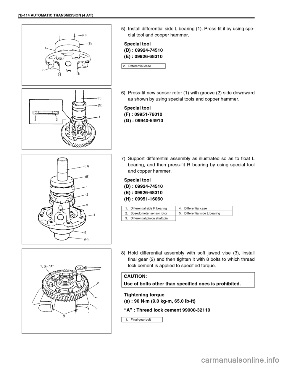
5) Install differential side L bearing (1). Press-fit it by using spe-
cial tool and copper hammer.
Special tool
(D) : 09924-74510
(E) : 09926-68310
.
6) Press-fit new sensor rotor (1) with groove (2) side downward
as shown by using special tools and copper hammer.
Special tool
(F) : 09951-76010
(G) : 09940-54910
7) Support differential assembly as illustrated so as to float L
bearing, and then press-fit R bearing by using special tool
and copper hammer.
Special tool
(D) : 09924-74510
(E) : 09926-68310
(H) : 09951-16060
8) Hold differential assembly with soft jawed vise (3), install
final gear (2) and then tighten it with 8 bolts to which thread
lock cement is applied to specified torque.
Tightening torque
(a) : 90 N·m (9.0 kg-m, 65.0 lb-ft)
“A” : Thread lock cement 99000-32110
2. Differential case
1. Differential side R bearing 4. Differential case
2. Speedometer sensor rotor 5. Differential side L bearing
3. Differential pinion shaft pin
CAUTION:
Use of bolts other than specified ones is prohibited.
1. Final gear bolt
Page 176 of 447
7B-134 AUTOMATIC TRANSMISSION (4 A/T)
63) Install vehicle speed sensor (for speedometer) (1), shift
cable bracket (2) and connector clamp bracket (3).
Tightening torque
Vehicle speed sensor bolt
(a) : 5.5 N·m (0.55 kg-m, 4.0 lb-ft)
Shift cable bracket bolts
(b) : 13 N·m (1.3 kg-m, 9.5 lb-ft)
Connector clamp bracket bolt : 8 N·m (0.8 kg-m, 6.0 lb-ft)
64) Install A/T fluid filler tube (2) and level gauge (1).
Tightening torque
A/T fluid filler tube bolt (a) : 19.5 N·m (1.95 kg-m, 14.5 lb-ft)
65) Install output shaft speed sensor (1) and input shaft speed
sensor (2).
Apply grease to O-ring of each sensor.
Tightening torque
Output shaft speed sensor bolt
(a) : 8 N·m (0.8 kg-m, 6.0 lb-ft)
Input shaft speed sensor bolt
(b) : 8 N·m (0.8 kg-m, 6.0 Ib-ft)
Grease : 99000-25030
66) Install engine mounting LH bracket.
Tightening torque
Engine mounting LH bracket bolts
(a) : 55 N·m (5.5 kg-m, 40.0 lb-ft)
Page 184 of 447

7C-2 CLUTCH
GENERAL DESCRIPTION
The clutch is a diaphragm-spring clutch of a dry single disc type. The diaphragm spring is of a tapering-finger
type, which is a solid ring in the outer diameter part, with a series of tapered fingers pointing inward.
The disc, carrying four torsional coil springs, is positioned on the transmission input shaft with an involute spline
fit.
The clutch cover is secured to the flywheel, and carries the diaphragm spring in such a way that the peripheral
edge part of the spring pushes on the pressure plate against the flywheel (with the disc in between), when the
clutch release bearing is held back. This is the engaged condition of the clutch.
Depressing the clutch pedal causes the release bearing to advance and pushes on the tips of the tapered fin-
gers of the diaphragm spring. When this happens, the diaphragm spring pulls the pressure plate away from the
flywheel, thereby interrupting the flow of drive from flywheel through clutch disc to transmission input shaft.
1. Crankshaft 6. Diaphragm spring
2. Flywheel 7. Release bearing
3. Clutch disc 8. Input shaft bearing
4. Pressure plate 9. Input shaft
5. Clutch cover 10. Release shaft