2000 SUZUKI SWIFT Meter
[x] Cancel search: MeterPage 298 of 447

8G-20 IMMOBILIZER CONTROL SYSTEM
INSPECTION OF ECM, IMMOBILIZER CON-
TROL MODULE AND ITS CIRCUIT
ECM, Immobilizer Control Module and its circuit can be checked
at ECM wiring couplers and Immobilizer Control Module wiring
coupler by measuring voltage. Described here is only inspection
of Immobilizer Control Module. For inspection of ECM, refer to
“ENGINE & EMISSION CONTROL INPUT/OUTPUT TABLE” in
Section 6E1.
Voltage Check
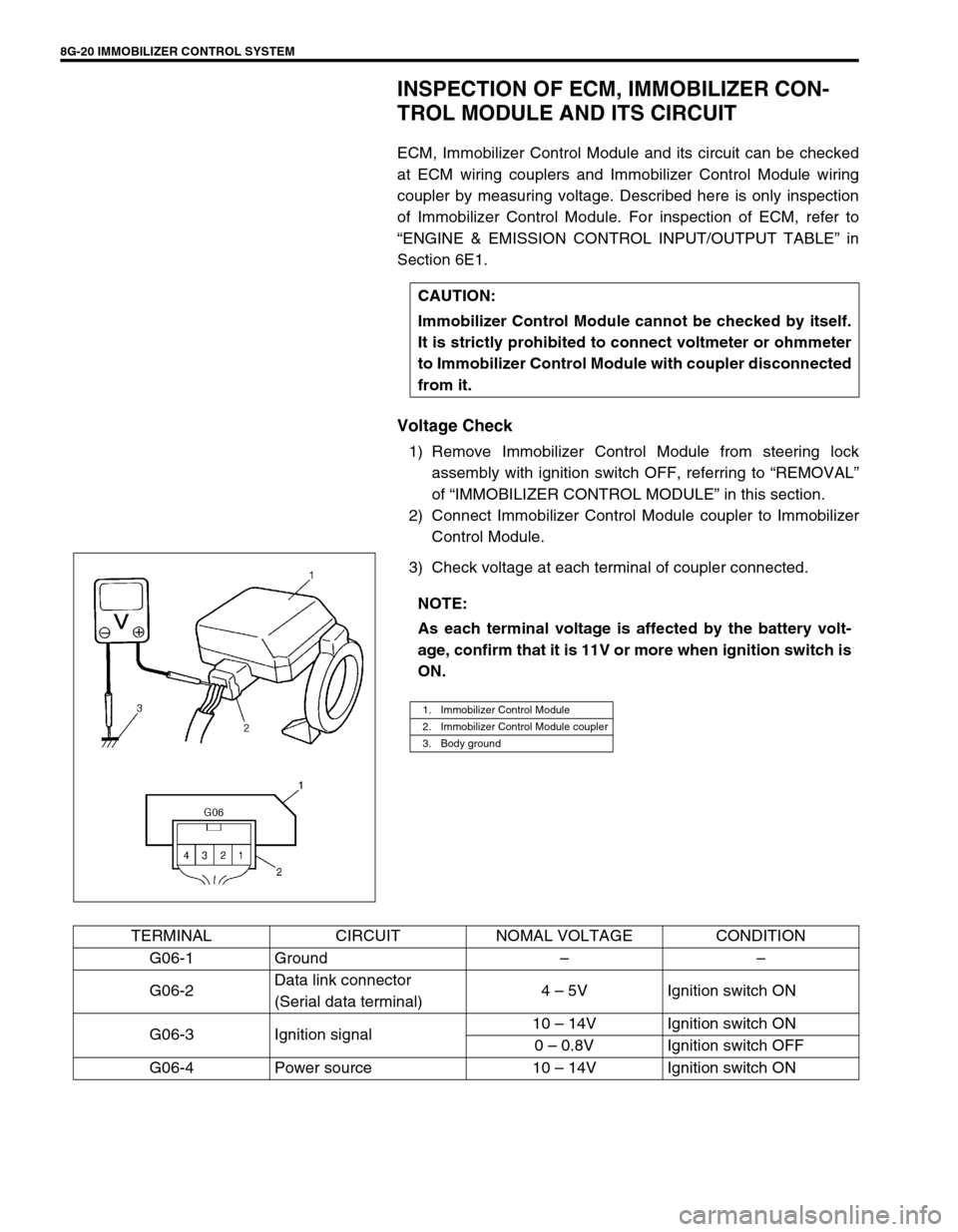
1) Remove Immobilizer Control Module from steering lock
assembly with ignition switch OFF, referring to “REMOVAL”
of “IMMOBILIZER CONTROL MODULE” in this section.
2) Connect Immobilizer Control Module coupler to Immobilizer
Control Module.
3) Check voltage at each terminal of coupler connected.CAUTION:
Immobilizer Control Module cannot be checked by itself.
It is strictly prohibited to connect voltmeter or ohmmeter
to Immobilizer Control Module with coupler disconnected
from it.
NOTE:
As each terminal voltage is affected by the battery volt-
age, confirm that it is 11V or more when ignition switch is
ON.
1. Immobilizer Control Module
2. Immobilizer Control Module coupler
3. Body ground
TERMINAL CIRCUIT NOMAL VOLTAGE CONDITION
G06-1 Ground––
G06-2Data link connector
(Serial data terminal)4 – 5V Ignition switch ON
G06-3 Ignition signal10 – 14V Ignition switch ON
0 – 0.8V Ignition switch OFF
G06-4 Power source 10 – 14V Ignition switch ON
Page 379 of 447

AIR BAG SYSTEM 10B-5
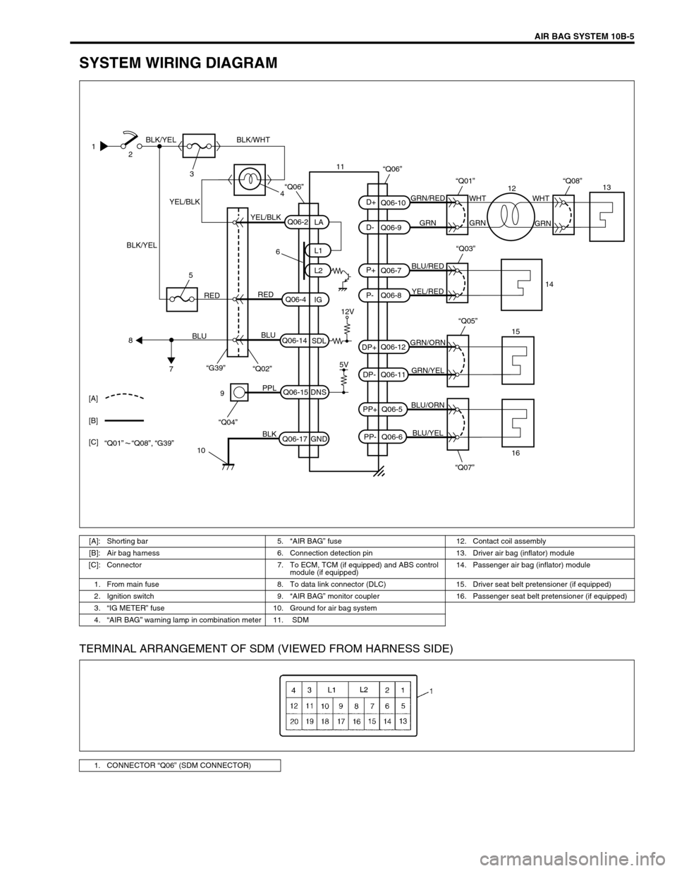
SYSTEM WIRING DIAGRAM
TERMINAL ARRANGEMENT OF SDM (VIEWED FROM HARNESS SIDE)
1
2
3
4 BLK/YEL
BLK/YELBLK/WHT
YEL/BLK
YEL/BLKGRN/RED
GRN GRNWHT WHT
GRN
BLU/RED
YEL/RED
GRN/ORN
GRN/YEL
BLU/ORN
BLU/YEL
6
12V
5V REDRED
BLU
BLU
5
8
7“G39”
“Q02”
“Q07” “Q05”
9
10PPL
BLK
“Q04”
Q06-2
Q06-4
Q06-14Q06-7
Q06-8 Q06-10
Q06-9
Q06-12
Q06-11
Q06-5
Q06-6 Q06-15
Q06-17L1
L2
IG
SDL
DNS
GNDLA
PP- PP+ DP- DP+P- P+ D- D+
“Q03”
“Q01”
“Q06”
“Q08”
15
161413
12 11
[A]
[B]
[C]
“Q01” “Q08”, “G39”
“Q06”
[A]: Shorting bar 5.“AIR BAG” fuse 12. Contact coil assembly
[B]: Air bag harness 6. Connection detection pin 13. Driver air bag (inflator) module
[C]: Connector 7. To ECM, TCM (if equipped) and ABS control
module (if equipped) 14. Passenger air bag (inflator) module
1. From main fuse 8. To data link connector (DLC) 15. Driver seat belt pretensioner (if equipped)
2. Ignition switch 9.“AIR BAG” monitor coupler 16. Passenger seat belt pretensioner (if equipped)
3.“IG METER” fuse 10. Ground for air bag system
4.“AIR BAG” warning lamp in combination meter 11. SDM
1. CONNECTOR “Q06” (SDM CONNECTOR)
Page 380 of 447

10B-6 AIR BAG SYSTEM
CONNECTOR “Q06” (SDM connector)
DIAGNOSIS
DIAGNOSTIC TROUBLE CODE (DTC)
The AIR BAG DIAGNOSTIC SYSTEM CHECK must always be the starting point of any air bag system diagno-
sis. The AIR BAG DIAGNOSTIC SYSTEM CHECK checks for proper “AIR BAG” warning lamp operation and
checks for air bag diagnostic trouble codes (DTCs) using on-board diagnosis function or SUZUKI scan tool.
USE OF SPECIAL TOOL
You should be familiar with the tools listed in this section under the heading SPECIAL TOOLS. You should be
able to measure voltage and resistance. You should be familiar with proper use of a scan tool such as Air Bag
Driver/Passenger Load Tool, Connector Test Adapter Kit and the Digital Multimeter.
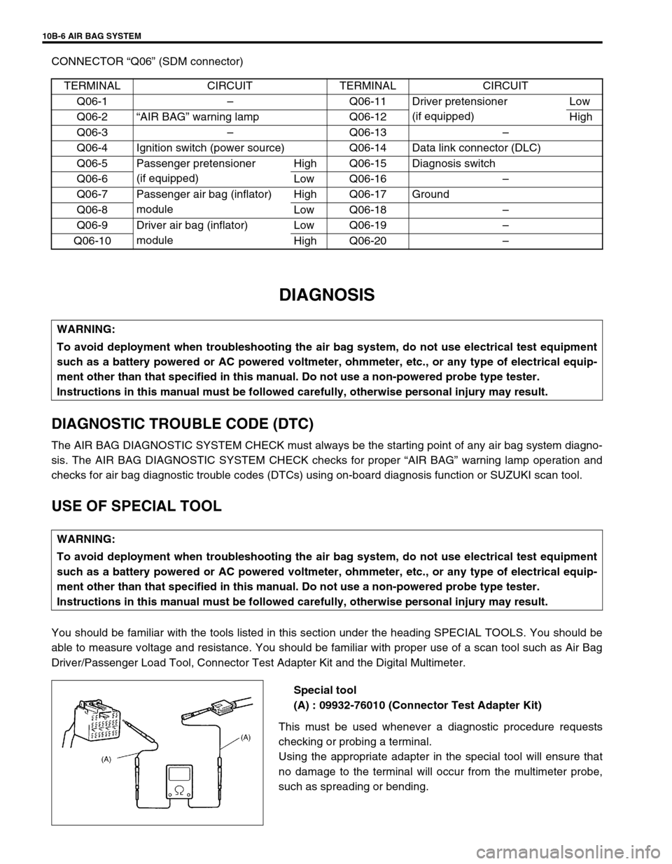
Special tool
(A) : 09932-76010 (Connector Test Adapter Kit)
This must be used whenever a diagnostic procedure requests
checking or probing a terminal.
Using the appropriate adapter in the special tool will ensure that
no damage to the terminal will occur from the multimeter probe,
such as spreading or bending. TERMINAL CIRCUIT TERMINAL CIRCUIT
Q06-1–Q06-11 Driver pretensioner
(if equipped)Low
Q06-2“AIR BAG” warning lamp Q06-12 High
Q06-3–Q06-13–
Q06-4 Ignition switch (power source) Q06-14 Data link connector (DLC)
Q06-5 Passenger pretensioner
(if equipped)High Q06-15 Diagnosis switch
Q06-6 Low Q06-16–
Q06-7 Passenger air bag (inflator)
moduleHigh Q06-17 Ground
Q06-8 Low Q06-18–
Q06-9 Driver air bag (inflator)
moduleLow Q06-19–
Q06-10 High Q06-20–
WARNING:
To avoid deployment when troubleshooting the air bag system, do not use electrical test equipment
such as a battery powered or AC powered voltmeter, ohmmeter, etc., or any type of electrical equip-
ment other than that specified in this manual. Do not use a non-powered probe type tester.
Instructions in this manual must be followed carefully, otherwise personal injury may result.
Page 383 of 447

AIR BAG SYSTEM 10B-9
AIR BAG DIAGNOSTIC SYSTEM CHECK
The diagnostic procedures used in this section are designed to find and repair air bag system malfunctions.
To get the best results, it is important to use the diagnostic flow tables and follow the sequence listed below.
1) Perform the AIR BAG DIAGNOSTIC SYSTEM CHECK FLOW TABLE.
(The AIR BAG DIAGNOSTIC SYSTEM CHECK FLOW TABLE must be the starting point of any air bag sys-
tem diagnosis.
The AIR BAG DIAGNOSTIC SYSTEM CHECK FLOW TABLE checks for proper “AIR BAG” warning lamp
operation through “AIR BAG” warning lamp and whether air bag diagnostic trouble codes exist.)
2) Refer to the proper diagnostic table as directed by the AIR BAG DIAGNOSTIC SYSTEM CHECK FLOW
TABLE.
(The AIR BAG DIAGNOSTIC SYSTEM CHECK FLOW TABLE will lead you to the correct table to diagnose
any air bag system malfunctions. Bypassing these procedures may result in extended diagnostic time, incor-
rect diagnosis and incorrect parts replacement.)
3) Repeat the AIR BAG DIAGNOSTIC SYSTEM CHECK FLOW TABLE after any repair or diagnostic proce-
dures have been performed.
(Performing the AIR BAG DIAGNOSTIC SYSTEM CHECK FLOW TABLE after all repair or diagnostic pro-
cedures will ensure that the repair has been made correctly and that no other malfunctions exist.)
FLOW TABLE TEST DESCRIPTION
STEP 1 : Check that “AIR BAG” warning lamp lights.
STEP 2 : Check that “AIR BAG” warning lamp lights.
STEP 3 : Check diagnosis switch circuit.
STEP 4 : Check that “AIR BAG” warning lamp flashes 6 times after ignition switch is turned ON.
STEP 6 : Check that history codes are in SDM memory. (using SUZUKI scan tool)
STEP 7 : Check that history codes are in SDM memory. (using monitor coupler)
STEP 9 : Check that current code is in SDM memory. (using SUZUKI scan tool)
STEP 10 : Check that current code is in SDM memory. (using monitor coupler)WARNING:
To avoid deployment when troubleshooting the air bag system, do not use electrical test equipment
such as a battery powered or AC powered voltmeter, ohmmeter, etc., or any type of electrical equip-
ment other than that specified in this manual. Do not use a non-powered probe type tester.
Instructions in this manual must be followed carefully, otherwise personal injury may result.
CAUTION:
The order in which diagnostic trouble codes are diagnosed is very important. Failure to diagnose the
diagnostic trouble codes in the order specified may result in extended diagnostic time, incorrect diag-
nosis and incorrect parts replacement.
Page 389 of 447

AIR BAG SYSTEM 10B-15
TABLE A - “AIR BAG” WARNING LAMP COMES ON STEADY
TABLE B - “AIR BAG” WARNING LAMP DOES NOT COME ON
TABLE C - “AIR BAG” WARNING LAMP FLASHES
TABLE D - “AIR BAG” WARNING LAMP CANNOT INDICATE FLASHING PAT-
TERN OF DTC
WIRING DIAGRAM
1. From main fuse 5.“AIR BAG” fuse 9. To ECM, TCM (if equipped) and ABS control
module (if equipped)
2. Ignition switch 6. Connection detection pin 10.“AIR BAG” monitor coupler
3.“IG·COIL METER” fuse 7. SDM 11. Ground for air bag system
4.“AIR BAG” warning lamp in combination meter 8. To DLC [A]: Air bag harness
1
2
34 BLK/YEL
BLK/YELBLK/WHTYEL/BLKYEL/BLK
6
REDRED
BLU
BLU
5
8
9
10
11
PPL
BLK
“Q04”“Q06”
Q06-2
Q06-4
Q06-14
Q06-15
Q06-17L1
L2
IG
SDL
DNS
GNDLA
7
[A]
12V
5V
“G39”“Q02”
CAUTION:
Be sure to perform AIR BAG DIAGNOSTIC SYSTEM CHECK before starting diagnosis according to
flow table.
When measurement of resistance or voltage is required in this table, use a tester along with a cor-
rect terminal adapter from special tool (Connector test adapter kit).
When a check for proper connection is required, refer to INTERMITTENT AND POOR CONNEC-
TIONS in this section.
If there is open circuit in the air bag wire harness, connector or terminal is found damaged, replace
the wire harness, connector and terminal as an assembly.
Page 390 of 447

10B-16 AIR BAG SYSTEM
TABLE TEST DESCRIPTION
Table A :
STEP 1 : Check “AIR BAG” fuse.
STEP 2 : Check power source circuit.
STEP 3 : Check “AIR BAG” warning lamp circuit.
Table B :
STEP 1 : Check combination meter power feed circuit.
STEP 2 : Check electrical connection check mechanism in SDM connector.
STEP 3 : Check “AIR BAG” warning lamp circuit.
STEP 4 : Check open in “AIR BAG” warning lamp circuit.
STEP 5 : Check short from “AIR BAG” warning lamp circuit to power circuit.
STEP 6 : Check “AIR BAG” bulb.
Table C and D :
STEP 1 : Check “AIR BAG” monitor coupler.
STEP 2 : Check diagnosis switch circuit for air bag system.
DIAGNOSTIC FLOW TABLE
Table A :
Fig. for STEP 2Step Action Yes No
1 1) Ignition switch OFF.
2) Remove and inspect “AIR BAG” fuse.
Is fuse good?Go to step 2.“RED” wire short to
ground.
After repair, replace “AIR
BAG” fuse.
2 1) Disconnect SDM.
2) Check proper connection to SDM at termi-
nal “Q06-4”.
3) If OK then check voltage between “Q06-4”
terminal of SDM connector and body
ground with ignition switch ON.
Is it 8 V or more?Go to step 3.“RED” wire (between “AIR
BAG” fuse and SDM con-
nector) open “BLK/YEL”
wire (between ignition
switch and “AIR BAG”
fuse) open or short to
ground
3 1) Disconnect 16-pin connector from combina-
tion meter. Refer to COMBINATION
METER in SECTION 8.
2) Check resistance between “Q06-2” termi-
nal of SDM connector and body ground.
Is resistance 10 Ω or more?Substitute a known-good
SDM and recheck.“YEL/BLK” wire (between
combination meter and
SDM connector) short to
ground
Page 391 of 447

AIR BAG SYSTEM 10B-17
Fig. for STEP 3
Special tool
(A) : 09932-76010
Table B :
NOTE:
Upon completion of inspection and repair work, perform following items.
Reconnect all air bag system components, ensure all components are properly mounted.
Repeat AIR BAG DIAGNOSTIC SYSTEM CHECK to confirm that the trouble has been corrected.
Step Action Yes No
1 1) Set parking brake.
2) Note combination meter when ignition
switch is turned ON.
Does the “BRAKE” indicator (warning lamp)
come ON?Go to step 2.“BLK/WHT” wire, “IG
METER” fuse or J/B
(between ignition switch
and combination meter)
open or short to ground
2 1) With ignition switch OFF, disconnect SDM.
2) Check electrical connection check mecha-
nism.
Is it in good condition?Go to step 3. Repair electrical connec-
tion check mechanism.
3 1) Disconnect SDM.
2) Check proper connection to SDM at termi-
nal “Q06-2”.
3) If OK then check voltage from “Q06-2” ter-
minal of SDM connector to body ground
with ignition switch ON.
Is it 8 V or more?Substitute a known-good
SDM and recheck.Go to step 4.
4 1) Remove combination meter. Refer to COM-
BINATION METER in SECTION 8.
2) Check proper connection to combination
meter at “YEL/BLK” terminal for “AIR BAG”
warning lamp and to SDM at terminal “Q06-
2”.
3) If OK then check resistance between “YEL/
BLK” wire terminal of combination meter
connector (16-pin connector) and “Q06-2”
terminal of SDM connector.
Is resistance 1 Ω or less?Go to step 5. Repair high resistance or
open in “YEL/BLK” wire
circuit (between combina-
tion meter and SDM).
Page 392 of 447

10B-18 AIR BAG SYSTEM
Fig. for STEP 2
Fig. for STEP 3 and 5
Special tool
(A) : 09932-76010
Fig. for STEP 4
Special tool
(A) : 09932-76010 5 1) Measure voltage from “Q06-2” terminal of
SDM connector to body ground with ignition
switch ON.
Is it 8 V or more?Repair short from “YEL/
BLK” wire circuit (between
combination meter and
SDM) to power circuit.Go to step 6.
6 1) Remove and inspect “AIR BAG” bulb.
Is bulb good?Substitute a known-good
combination meter and
recheck.Replace bulb. Step Action Yes No
1. 16-pin connector (for combination meter)
2.“YEL/BLK” wire terminal
NOTE:
Upon completion of inspection and repair work, perform following items.
Reconnect all air bag system components, ensure all components are properly mounted.
Repeat AIR BAG DIAGNOSTIC SYSTEM CHECK to confirm that the trouble has been corrected.