Page 16 of 447

7A-16 MANUAL TRANSMISSION
TRANSMISSION UNIT
DISMOUNTING
Under Hood
1) Disconnect negative cable at battery.
2) Undo wiring harness clamps, disconnect backup lamp switch
coupler, VSS coupler and ground cable.
3) Disconnect clutch cable from clutch release lever and
bracket.
4) Disconnect gear shift and select control cables.
5) Remove water pipe bracket bolts from transmission.
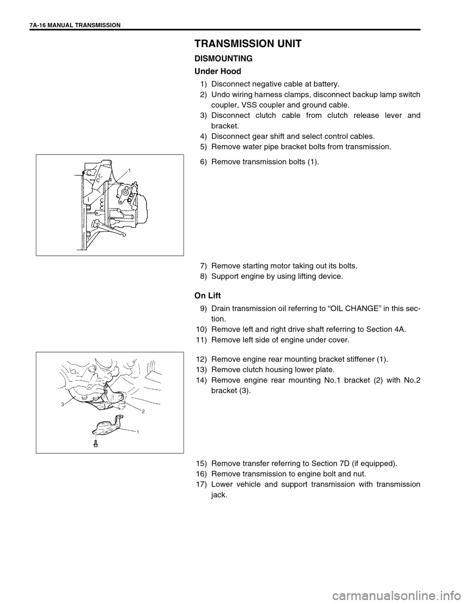
6) Remove transmission bolts (1).
7) Remove starting motor taking out its bolts.
8) Support engine by using lifting device.
On Lift
9) Drain transmission oil referring to “OIL CHANGE” in this sec-
tion.
10) Remove left and right drive shaft referring to Section 4A.
11) Remove left side of engine under cover.
12) Remove engine rear mounting bracket stiffener (1).
13) Remove clutch housing lower plate.
14) Remove engine rear mounting No.1 bracket (2) with No.2
bracket (3).
15) Remove transfer referring to Section 7D (if equipped).
16) Remove transmission to engine bolt and nut.
17) Lower vehicle and support transmission with transmission
jack.
Page 18 of 447

7A-18 MANUAL TRANSMISSION
2) Using special tool, remove circlip (1) and then hub plate (2).
Special tool
(A) : 09900-06107
3) If equipped, remove shift fork plug (1) and guide ball (2).
4) Drive out spring pin (3) by using special tool and hammer.
Special tool
(B) : 09922-85811
5) If equipped, remove circlip (4) by using circlip plier.
6) Remove gear shift fork (2), sleeve & hub assembly (3), syn-
chronizer ring spring, synchronizer ring and 5th gear all
together.Use gear puller (1) for removal if spline fitting of hub
is tight.
7) Unfasten caulking of countershaft nut, install input shaft 5th
gear (1) and special tool to stop rotation of shafts, and then
remove countershaft nut (2).
Special tool
(C) : 09927-76010
8) Remove special tool, input shaft 5th gear, needle bearing of
separated steel cage type and then counter shaft 5th gear.
Gear puller (4) would be necessary if spline fitting of counter
shaft 5th gear (3) is tight.
9) Remove plate screws (1) and take off left case plate (2), and
then bearing set shim.
NOTE:
Use of magnet would facilitate removal of guide ball.
Page 19 of 447
MANUAL TRANSMISSION 7A-19
GEAR SHIFTER, INPUT SHAFT AND COUNTER
SHAFT
1) Remove gear shift interlock bolt (1) and 5th to reverse inter-
lock guide bolt (2) from transmission case.
2) Remove gear shifter assembly (3).
3) Remove gear shift locating bolts (1) with washers, then take
out locating springs and steel balls.
4) Remove back up light switch (2).
5) Remove reverse shaft bolt (1) with washer.
6) Remove case bolts (2) from outside and another bolts from
clutch housing side.
7) Tapping left case (3) flanges with plastic hammer, remove
left case.
8) Pull out reverse gear shaft (1) with washer (2), then take off
reverse idler gear (3).
9) Remove reverse gear shift lever bolts (4), and reverse gear
shift lever (5).
10) Pull out 5th & reverse gear shift guide shaft (6) together with
5th & reverse gear shift shaft (7).
Page 20 of 447
7A-20 MANUAL TRANSMISSION
11) Tapping input shaft end with plastic hammer, push it out as
assembly from case a little, then take out input shaft assem-
bly (1), counter shaft assembly (2), high speed gear shift
shaft (3) and low speed gear shift shaft (4) all at once.
12) Remove counter shaft left bearing cup from left case.
13) Remove differential side left oil seal also from left case.
RIGHT CASE
1) Remove differential gear assembly (1) from right case (2).
2) Remove bolt and then pull out VSS (3).
3) If input shaft right bearing has been left in right case, pull it
out by using special tools.
Remove input shaft oil seal (1) by using special tools.
Special tool
(A) : 09930-30104
(B) : 09923-74510
4) Also pull out countershaft right bearing cup (2) by using spe-
cial tools.
Special tool
09941-64511
09923-30104
Page 29 of 447

MANUAL TRANSMISSION 7A-29
GEAR SHIFTER
Gear Shift and Select Shaft Assembly
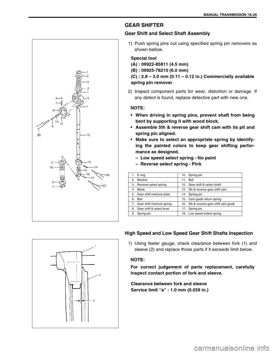
1) Push spring pins out using specified spring pin removers as
shown bellow.
Special tool
(A) : 09922-85811 (4.5 mm)
(B) : 09925-78210 (6.0 mm)
(C) : 2.8 – 3.0 mm (0.11 – 0.12 in.) Commercially available
spring pin remover
2) Inspect component parts for wear, distortion or damage. If
any detect is found, replace detective part with new one.
High Speed and Low Speed Gear Shift Shafts Inspection
1) Using feeler gauge, check clearance between fork (1) and
sleeve (2) and replace those parts if it exceeds limit below.
Clearance between fork and sleeve
Service limit “a” : 1.0 mm (0.039 in.) NOTE:
When driving in spring pins, prevent shaft from being
bent by supporting it with wood block.
Assemble 5th & reverse gear shift cam with its pit and
spring pin aligned.
Make sure to select an appropriate spring by identify-
ing the painted colors to keep gear shifting perfor-
mance as designed.
– Low speed select spring - No paint
– Reverse select spring - Pink
1. E-ring 10. Spring pin
2. Washer 11. Ball
3. Reverse select spring 12. Gear shift & select shaft
4. Blank 13. 5th & reverse gear shift cam
5. Gear shift interlock plate 14. Spring pin
6. Ball 15. Cam guide return spring
7. Gear shift interlock spring 16. 5th & reverse gear shift cam guide
8. Gear shift & select lever 17. Spring pin
9. Spring pin 18. Low speed select spring
NOTE:
For correct judgement of parts replacement, carefully
inspect contact portion of fork and sleeve.
Page 30 of 447

7A-30 MANUAL TRANSMISSION
2) Insert each gear shift shaft into case and check that it moves
smoothly. If it doesn’t, correct by using oilstone, reamer or
the like.
5th & Reverse Gear Shifter
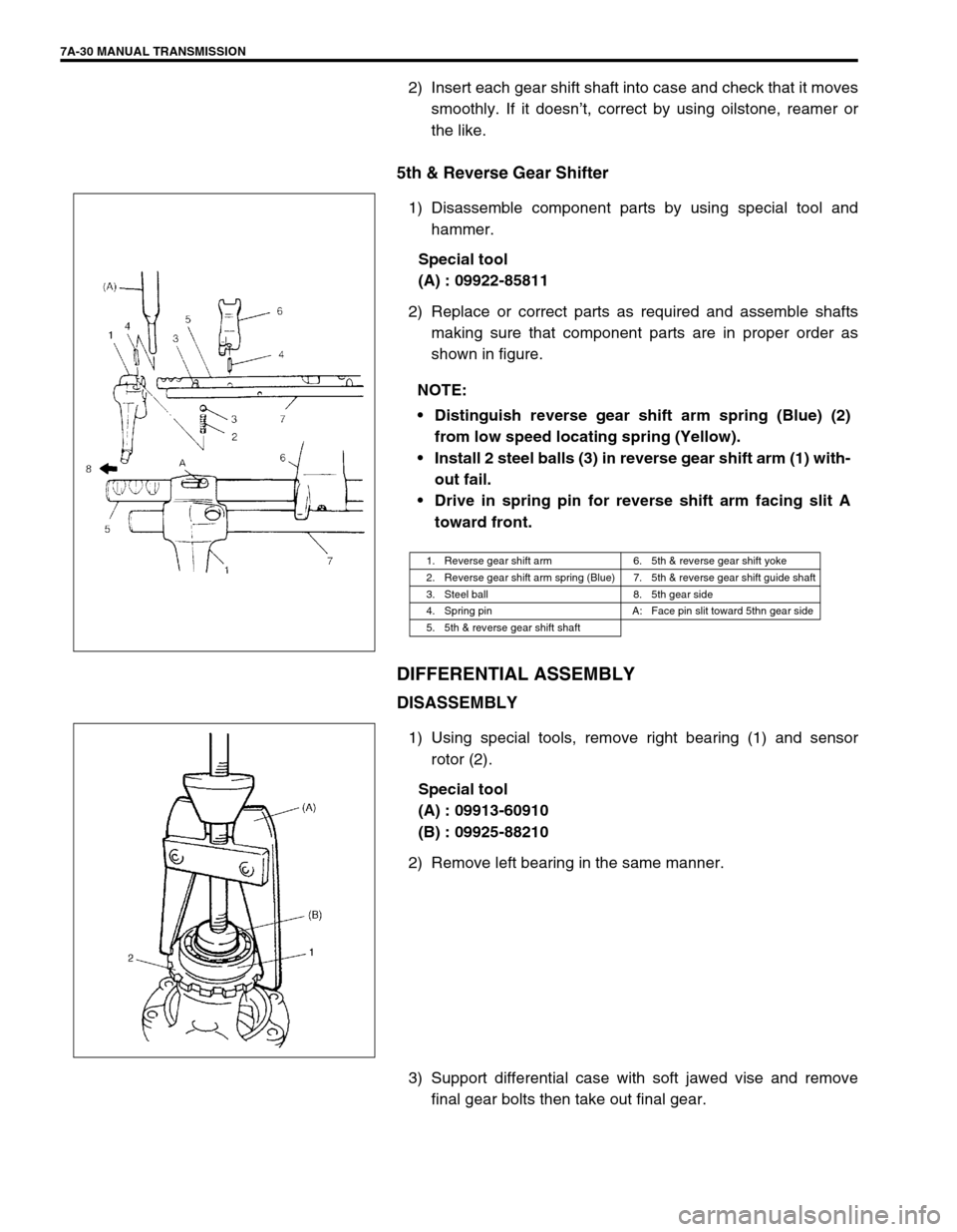
1) Disassemble component parts by using special tool and
hammer.
Special tool
(A) : 09922-85811
2) Replace or correct parts as required and assemble shafts
making sure that component parts are in proper order as
shown in figure.
DIFFERENTIAL ASSEMBLY
DISASSEMBLY
1) Using special tools, remove right bearing (1) and sensor
rotor (2).
Special tool
(A) : 09913-60910
(B) : 09925-88210
2) Remove left bearing in the same manner.
3) Support differential case with soft jawed vise and remove
final gear bolts then take out final gear. NOTE:
Distinguish reverse gear shift arm spring (Blue) (2)
from low speed locating spring (Yellow).
Install 2 steel balls (3) in reverse gear shift arm (1) with-
out fail.
Drive in spring pin for reverse shift arm facing slit A
toward front.
1. Reverse gear shift arm 6. 5th & reverse gear shift yoke
2. Reverse gear shift arm spring (Blue) 7. 5th & reverse gear shift guide shaft
3. Steel ball 8. 5th gear side
4. Spring pin A: Face pin slit toward 5thn gear side
5. 5th & reverse gear shift shaft
Page 33 of 447

MANUAL TRANSMISSION 7A-33
UNIT ASSEMBLY
DIFFERENTIAL TO LEFT CASE
ASSEMBLY
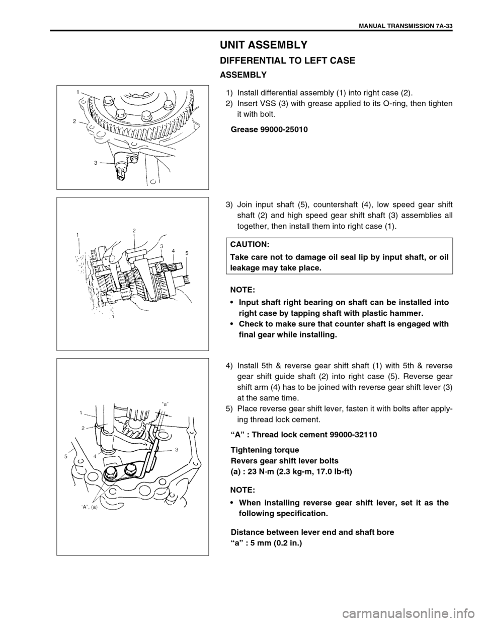
1) Install differential assembly (1) into right case (2).
2) Insert VSS (3) with grease applied to its O-ring, then tighten
it with bolt.
Grease 99000-25010
3) Join input shaft (5), countershaft (4), low speed gear shift
shaft (2) and high speed gear shift shaft (3) assemblies all
together, then install them into right case (1).
4) Install 5th & reverse gear shift shaft (1) with 5th & reverse
gear shift guide shaft (2) into right case (5). Reverse gear
shift arm (4) has to be joined with reverse gear shift lever (3)
at the same time.
5) Place reverse gear shift lever, fasten it with bolts after apply-
ing thread lock cement.
“A” : Thread lock cement 99000-32110
Tightening torque
Revers gear shift lever bolts
(a) : 23 N·m (2.3 kg-m, 17.0 lb-ft)
Distance between lever end and shaft bore
“a” : 5 mm (0.2 in.)
CAUTION:
Take care not to damage oil seal lip by input shaft, or oil
leakage may take place.
NOTE:
Input shaft right bearing on shaft can be installed into
right case by tapping shaft with plastic hammer.
Check to make sure that counter shaft is engaged with
final gear while installing.
NOTE:
When installing reverse gear shift lever, set it as the
following specification.
Page 34 of 447

7A-34 MANUAL TRANSMISSION
6) Make reverse idler gear (1) with reverse gear shift lever (2),
insert reverse gear shaft (3) into case through idler gear and
then align “A” in shaft with “B” in case.
7) Clean mating surfaces of both right and left cases, apply
sealant to right case (2) by using a nozzle as shown in figure
by such amount that its section is 1.5mm (0.059 in.) in diam-
eter then mate it with left case (1).
“B” : Sealant 99000-31110
8) Tighten case bolts (3) from left case side to specified torque.
Tightening torque
Transmission case bolts (b) : 19 N·m (1.9 kg-m, 14.0 Ib-ft)
9) Install reverse shaft bolt (4) to which thread lock cement
have been applied with aluminum washer and tighten it.
“A” : Thread lock cement 99000-32110
Tightening torque
Reverse shaft bolt (c) : 23 N·m (2.3 kg-m, 17.0 lb-ft)
10) Install another case bolts from clutch housing side and
tighten them to specification. NOTE:
Distance “a” can be measured by installing reverse
gear shaft provisionally.
When “a” is 5 mm (0.2 in.), clearance between reverse
idler gear groove and shift lever end will be 1 mm (0.04
in.).
NOTE:
Make sure that washer (4) has been installed in shaft at
above the gear.
Check to confirm that reverse gear shift lever end has
clearance 1 mm (0.04 in.) to idler gear groove.