Page 347 of 557
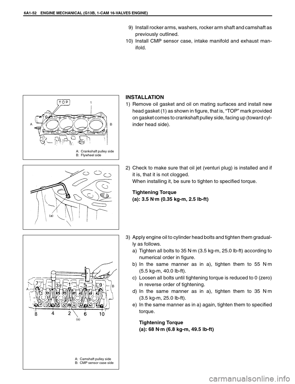
A: Crankshaft pulley side
B: Flywheel side
A: Camshaft pulley side
B: CMP sensor case side
6A1-52 ENGINE MECHANICAL (G13B, 1-CAM 16-VALVES ENGINE)
9) Install rocker arms, washers, rocker arm shaft and camshaft as
previously outlined.
10) Install CMP sensor case, intake manifold and exhaust man-
ifold.
INSTALLATION
1) Remove oil gasket and oil on mating surfaces and install new
head gasket (1) as shown in figure, that is, “TOP” mark provided
on gasket comes to crankshaft pulley side, facing up (toward cyl-
inder head side).
2) Check to make sure that oil jet (venturi plug) is installed and if
it is, that it is not clogged.
When installing it, be sure to tighten to specified torque.
Tightening Torque
(a): 3.5 N
.m (0.35 kg-m, 2.5 lb-ft)
3) Apply engine oil to cylinder head bolts and tighten them gradual-
ly as follows.
a) Tighten all bolts to 35 N
.m (3.5 kg-m, 25.0 lb-ft) according to
numerical order in figure.
b) In the same manner as in a), tighten them to 55 N
.m
(5.5 kg-m, 40.0 lb-ft).
c) Loosen all bolts until tightening torque is reduced to 0 (zero)
in reverse order of tightening.
d) In the same manner as in a), tighten them to 35 N
.m
(3.5 kg-m, 25.0 lb-ft).
e) In the same manner as in a) again, tighten them to specified
torque.
Tightening Torque
(a): 68 N
.m (6.8 kg-m, 49.5 lb-ft)
Page 353 of 557
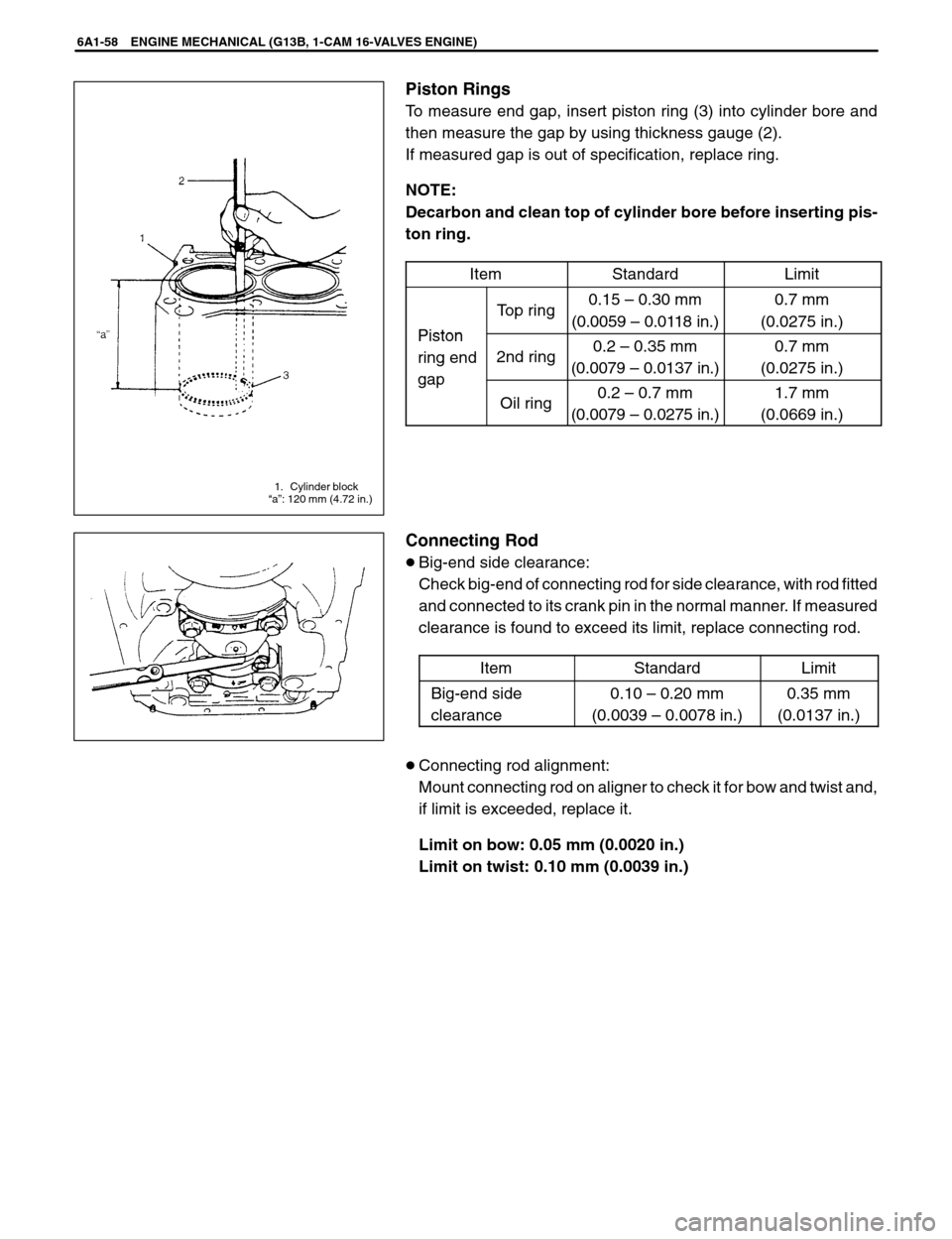
1. Cylinder block
“a”: 120 mm (4.72 in.)
6A1-58 ENGINE MECHANICAL (G13B, 1-CAM 16-VALVES ENGINE)
Piston Rings
To measure end gap, insert piston ring (3) into cylinder bore and
then measure the gap by using thickness gauge (2).
If measured gap is out of specification, replace ring.
NOTE:
Decarbon and clean top of cylinder bore before inserting pis-
ton ring.
Item
StandardLimit
Piston
Top ring0.15 – 0.30 mm
(0.0059 – 0.0118 in.)0.7 mm
(0.0275 in.)
Piston
ring end
gap
2nd ring0.2 – 0.35 mm
(0.0079 – 0.0137 in.)0.7 mm
(0.0275 in.)
ga
Oil ring0.2 – 0.7 mm
(0.0079 – 0.0275 in.)1.7 mm
(0.0669 in.)
Connecting Rod
�Big-end side clearance:
Check big-end of connecting rod for side clearance, with rod fitted
and connected to its crank pin in the normal manner. If measured
clearance is found to exceed its limit, replace connecting rod.
Item
StandardLimit
Big-end side
clearance0.10 – 0.20 mm
(0.0039 – 0.0078 in.)0.35 mm
(0.0137 in.)
�Connecting rod alignment:
Mount connecting rod on aligner to check it for bow and twist and,
if limit is exceeded, replace it.
Limit on bow: 0.05 mm (0.0020 in.)
Limit on twist: 0.10 mm (0.0039 in.)
Page 354 of 557
ENGINE MECHANICAL (G13B, 1-CAM 16-VALVES ENGINE) 6A1-59
Crank Pin and Connecting Rod Bearings
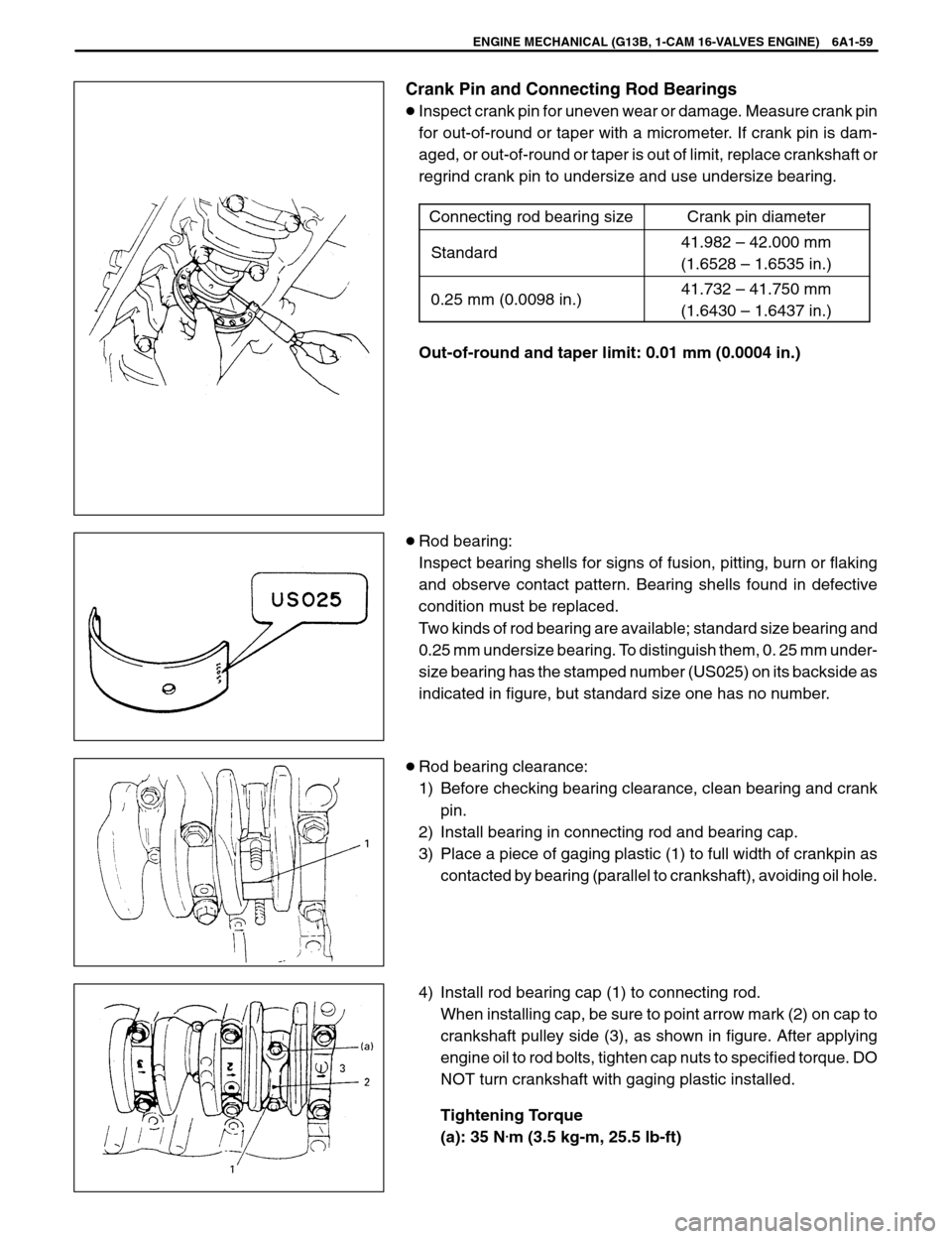
�Inspect crank pin for uneven wear or damage. Measure crank pin
for out-of-round or taper with a micrometer. If crank pin is dam-
aged, or out-of-round or taper is out of limit, replace crankshaft or
regrind crank pin to undersize and use undersize bearing.
Connecting rod bearing size
Crank pin diameter
Standard41.982 – 42.000 mm
(1.6528 – 1.6535 in.)
0.25 mm (0.0098 in.)41.732 – 41.750 mm
(1.6430 – 1.6437 in.)
Out-of-round and taper limit: 0.01 mm (0.0004 in.)
�Rod bearing:
Inspect bearing shells for signs of fusion, pitting, burn or flaking
and observe contact pattern. Bearing shells found in defective
condition must be replaced.
Two kinds of rod bearing are available; standard size bearing and
0.25 mm undersize bearing. To distinguish them, 0. 25 mm under-
size bearing has the stamped number (US025) on its backside as
indicated in figure, but standard size one has no number.
�Rod bearing clearance:
1) Before checking bearing clearance, clean bearing and crank
pin.
2) Install bearing in connecting rod and bearing cap.
3) Place a piece of gaging plastic (1) to full width of crankpin as
contacted by bearing (parallel to crankshaft), avoiding oil hole.
4) Install rod bearing cap (1) to connecting rod.
When installing cap, be sure to point arrow mark (2) on cap to
crankshaft pulley side (3), as shown in figure. After applying
engine oil to rod bolts, tighten cap nuts to specified torque. DO
NOT turn crankshaft with gaging plastic installed.
Tightening Torque
(a): 35 N
.m (3.5 kg-m, 25.5 lb-ft)
Page 358 of 557
ENGINE MECHANICAL (G13B, 1-CAM 16-VALVES ENGINE) 6A1-63
6) Reverse removal procedure for installation, as previously out-
lined.
7) Adjust water pump drive belt tension referring to Section 6B.
8) Adjust power steering pump belt tension or A / C compressor
belt tension, if equipped.
Refer to Section 0B.
9) Adjust accelerator cable play.
Refer to Section 6E.
10) Check to ensure that all removed parts are back in place. Rein-
stall any necessary parts which have not been reinstalled.
11) Refill engine with engine oil by referring to item “ENGINE OIL
CHANGE” in Section 0B.
12) Refill cooling system referring to Section 6B.
13) Connect negative cable at battery.
14) Check ignition timing referring to Section 6F.
15) Verify that there is no fuel leakage, coolant leakage, oil leakage
and exhaust gas leakage at each connection.
Page 361 of 557
6A1-66 ENGINE MECHANICAL (G13B, 1-CAM 16-VALVES ENGINE)
15) Remove exhaust No.1 pipe.
16) Remove right and left engine under covers.
17) Remove gear shift control shaft from transmission and remove
extension rod (M / T).
18) Drain engine and transmission oil.
19) Disconnect drive shaft joints from differential gears of trans-
mission or center bearing support referring to Section 4. In this
case, it is not necessary to disconnect drive shafts from steer-
ing knuckle.
20) With hoses connected, detach A / C compressor and/or P / S
pump with bracket from cylinder block, if equipped.
NOTE:
Suspend removed compressor and/or pump at a place
where no damage will be caused during removal and
installation of engine with transmission.
21) Disconnect P / S hose from P / S oil pump. (if equipped)
NOTE:
Plug pipe, hose and pump port.
22) Install support device.
23) Remove rear mounting from body. (For M / T model)
Remove rear torque rod (For A / T model).
24) Remove engine left mounting from body.
25) Remove engine right mounting from right mounting bracket
and stiffener.
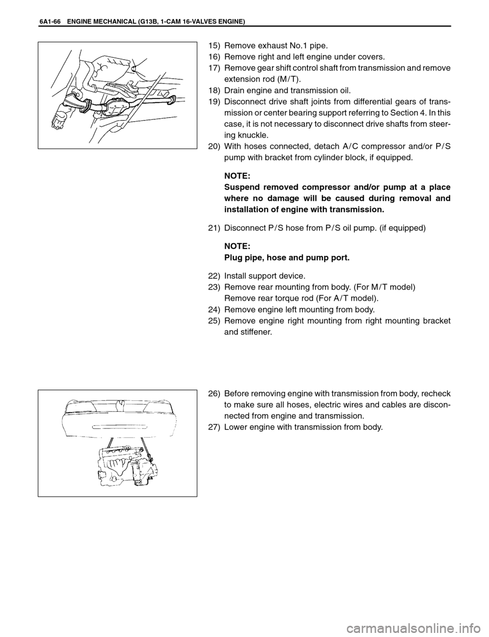
26) Before removing engine with transmission from body, recheck
to make sure all hoses, electric wires and cables are discon-
nected from engine and transmission.
27) Lower engine with transmission from body.
Page 362 of 557
(a)
1
2
3
(a)
(a)
6
74
5
(a)
M/TM/T
9
(a)
4
7
(a)
8
1. Right mounting
2. Right mounting
bracket
3. Left mounting
4. Left mounting bracket
5. Left mounting bracket
stiffener6. Rear mounting
7. Rear mounting
bracket
8. Rear torque rod
9. Rear torque rod
bracket
ENGINE MECHANICAL (G13B, 1-CAM 16-VALVES ENGINE) 6A1-67
INSTALLATION
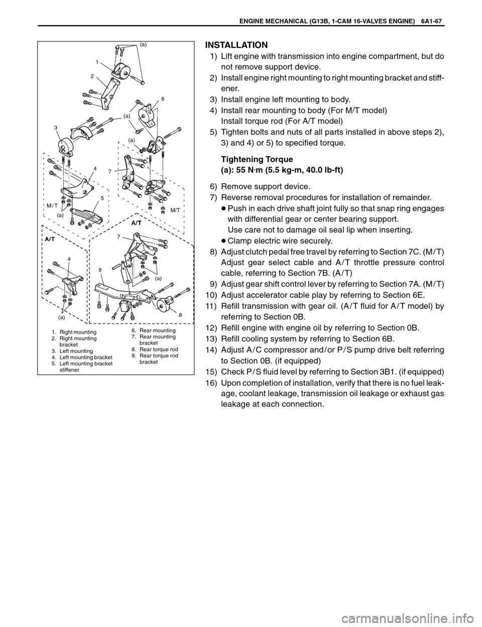
1) Lift engine with transmission into engine compartment, but do
not remove support device.
2) Install engine right mounting to right mounting bracket and stiff-
ener.
3) Install engine left mounting to body.
4) Install rear mounting to body (For M/T model)
Install torque rod (For A/T model)
5) Tighten bolts and nuts of all parts installed in above steps 2),
3) and 4) or 5) to specified torque.
Tightening Torque
(a): 55 N
.m (5.5 kg-m, 40.0 lb-ft)
6) Remove support device.
7) Reverse removal procedures for installation of remainder.
�Push in each drive shaft joint fully so that snap ring engages
with differential gear or center bearing support.
Use care not to damage oil seal lip when inserting.
�Clamp electric wire securely.
8) Adjust clutch pedal free travel by referring to Section 7C. (M / T)
Adjust gear select cable and A / T throttle pressure control
cable, referring to Section 7B. (A / T)
9) Adjust gear shift control lever by referring to Section 7A. (M / T)
10) Adjust accelerator cable play by referring to Section 6E.
11) Refill transmission with gear oil. (A / T fluid for A / T model) by
referring to Section 0B.
12) Refill engine with engine oil by referring to Section 0B.
13) Refill cooling system by referring to Section 6B.
14) Adjust A / C compressor and / or P / S pump drive belt referring
to Section 0B. (if equipped)
15) Check P / S fluid level by referring to Section 3B1. (if equipped)
16) Upon completion of installation, verify that there is no fuel leak-
age, coolant leakage, transmission oil leakage or exhaust gas
leakage at each connection.
Page 366 of 557
1. Gaging plastic
ENGINE MECHANICAL (G13B, 1-CAM 16-VALVES ENGINE) 6A1-71
Main Bearings
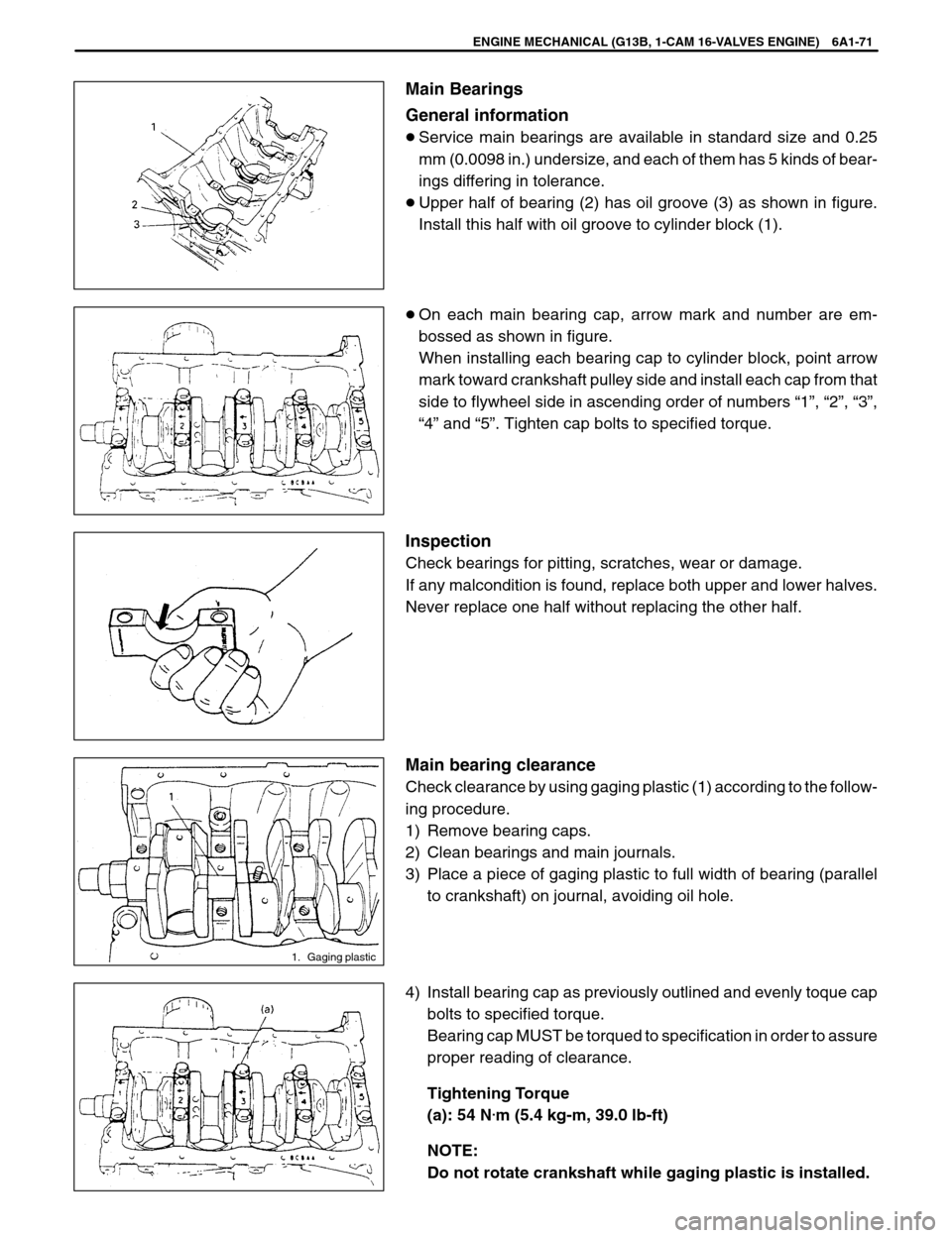
General information
�Service main bearings are available in standard size and 0.25
mm (0.0098 in.) undersize, and each of them has 5 kinds of bear-
ings differing in tolerance.
�Upper half of bearing (2) has oil groove (3) as shown in figure.
Install this half with oil groove to cylinder block (1).
�On each main bearing cap, arrow mark and number are em-
bossed as shown in figure.
When installing each bearing cap to cylinder block, point arrow
mark toward crankshaft pulley side and install each cap from that
side to flywheel side in ascending order of numbers “1”, “2”, “3”,
“4” and “5”. Tighten cap bolts to specified torque.
Inspection
Check bearings for pitting, scratches, wear or damage.
If any malcondition is found, replace both upper and lower halves.
Never replace one half without replacing the other half.
Main bearing clearance
Check clearance by using gaging plastic (1) according to the follow-
ing procedure.
1) Remove bearing caps.
2) Clean bearings and main journals.
3) Place a piece of gaging plastic to full width of bearing (parallel
to crankshaft) on journal, avoiding oil hole.
4) Install bearing cap as previously outlined and evenly toque cap
bolts to specified torque.
Bearing cap MUST be torqued to specification in order to assure
proper reading of clearance.
Tightening Torque
(a): 54 N
.m (5.4 kg-m, 39.0 lb-ft)
NOTE:
Do not rotate crankshaft while gaging plastic is installed.
Page 370 of 557
ENGINE MECHANICAL (G13B, 1-CAM 16-VALVES ENGINE) 6A1-75
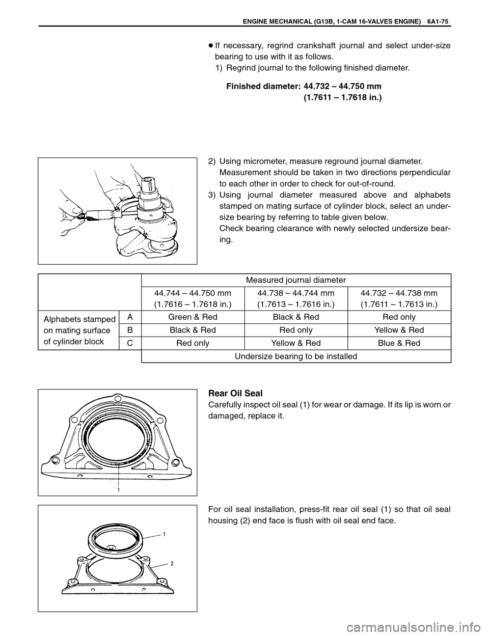
�If necessary, regrind crankshaft journal and select under-size
bearing to use with it as follows.
1) Regrind journal to the following finished diameter.
Finished diameter: 44.732 – 44.750 mm
(1.7611 – 1.7618 in.)
2) Using micrometer, measure reground journal diameter.
Measurement should be taken in two directions perpendicular
to each other in order to check for out-of-round.
3) Using journal diameter measured above and alphabets
stamped on mating surface of cylinder block, select an under-
size bearing by referring to table given below.
Check bearing clearance with newly selected undersize bear-
ing.
Measured journal diameter
44.744 – 44.750 mm
(1.7616 – 1.7618 in.)44.738 – 44.744 mm
(1.7613 – 1.7616 in.)44.732 – 44.738 mm
(1.7611 – 1.7613 in.)
Alphabets stampedAGreen & RedBlack & RedRed only
on mating surfaceBBlack & RedRed onlyYellow & Red
of cylinder block
CRed onlyYellow & RedBlue & Red
Undersize bearing to be installed
Rear Oil Seal
Carefully inspect oil seal (1) for wear or damage. If its lip is worn or
damaged, replace it.
For oil seal installation, press-fit rear oil seal (1) so that oil seal
housing (2) end face is flush with oil seal end face.