Page 39 of 557

For A / TFor M / T
MAINTENANCE AND LUBRICATION 0B-9
1) Remove radiator cap when engine is cool.
2) Loosen radiator drain plug (1) to drain coolant.
3) Remove reservoir and drain.
4) Tighten drain plug securely. Also install reservoir.
5) Slowly pour specified amount of coolant to the base of radiator
filler neck, and run engine, with radiator cap removed, until ra-
diator upper hose is hot. This drives out any air which may still
be trapped within cooling system. Add coolant as necessary un-
til coolant level reaches filler throat of radiator. Reinstall radiator
cap.
6) Add coolant to reservoir (1) so that its level aligns with Full mark
(2). Then, reinstall cap to reservoir aligning match marks (3) on
reservoir and cap.
ITEM 1-6
Exhaust System Inspection
WARNING:
To avoid danger of being burned, do not touch exhaust sys-
tem when it is still hot.
Any service on exhaust system should be performed when
it is cool.
When carrying out periodic maintenance or vehicle is raised for oth-
er service, check exhaust system as follows:
�Check rubber mountings for damage and deterioration.
�Check exhaust system for leakage, loose connections, dents,
and damages.
If bolts or nuts are loose, tighten them to specification. Refer to
SECTION 6K for torque specification of bolts and nuts.
�Check nearby body areas for damaged, missing or mispositioned
parts, open seams, holes, loose connections or other defects
which could permit exhaust fumes to seep into vehicle.
�Make sure that exhaust system components have enough clear-
ance from underbody to avoid overheating and possible damage
to floor carpet.
�Any defects should be fixed at once.
Page 320 of 557
1. Oil pan:
Apply sealant 99000-31150 to
oil pan mating surface.
2. Oil pump strainer
3. Seal
4. Drain plug gasket
5. Drain plug
6. CKP sensor : Tightening Torque
: Do not reuse
ENGINE MECHANICAL (G13B, 1-CAM 16-VALVES ENGINE) 6A1-25
OIL PAN AND OIL PUMP STRAINER
REMOVAL
1) Raise vehicle.
2) Drain engine oil by removing drain plug (1).
3) Remove right side of engine under cover.
4) Disconnect CKP sensor coupler and remove CKP sensor (1) by
removing its bolt. Then remove CKP sensor wire harness from
clamp.
5) Remove clutch housing (torque converter housing for A / T) low-
er plate.
Page 336 of 557
: Do not reuse
1. Valve cotters
2. Valve spring retainer
3. Valve spring:
be sure to position
spring in place with its
bottom end (small-pitch
end) facing the bottom
(valve spring seat side).
4. Valve stem seal
5. Valve spring seat
6. Exhaust valve
7. Intake valve
8. Cylinder head bolt
9. Camshaft housing bolt10. Camshaft housing:
Apply sealant to mating surface of
No.1 and No.6 housings.
11. Valve guide
12. Oil venturi plug
13. Cylinder head gasket:
“TOP” mark provided on gasket comes to
crankshaft pulley side, facing up
(toward cylinder head side).
14. Dowel pin
: Tightening Torque
: Apply engine oil to sliding
: surfaces of each part.
3.5 N.m (0.35 kg-m)
ENGINE MECHANICAL (G13B, 1-CAM 16-VALVES ENGINE) 6A1-41
VALVES AND CYLINDER HEAD
REMOVAL
1) Relieve fuel pressure according to procedure described in Sec-
tion 6.
2) Disconnect negative cable at battery.
3) Drain cooling system.
4) Remove air cleaner outlet hose as previously outlined.
Page 349 of 557

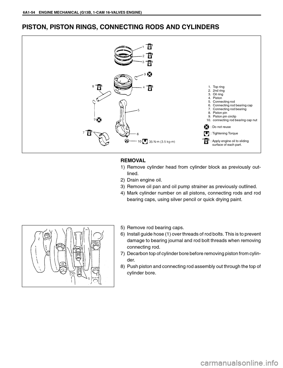
1. Top ring
2. 2nd ring
3. Oil ring
4. Piston
5. Connecting rod
6. Connecting rod bearing cap
7. Connecting rod bearing
8. Piston pin
9. Piston pin circlip
10. connecting rod bearing cap nut
: Do not reuse
: Tightening Torque
: Apply engine oil to sliding
: surface of each part.
6
10
6A1-54 ENGINE MECHANICAL (G13B, 1-CAM 16-VALVES ENGINE)
PISTON, PISTON RINGS, CONNECTING RODS AND CYLINDERS
REMOVAL
1) Remove cylinder head from cylinder block as previously out-
lined.
2) Drain engine oil.
3) Remove oil pan and oil pump strainer as previously outlined.
4) Mark cylinder number on all pistons, connecting rods and rod
bearing caps, using silver pencil or quick drying paint.
5) Remove rod bearing caps.
6) Install guide hose (1) over threads of rod bolts. This is to prevent
damage to bearing journal and rod bolt threads when removing
connecting rod.
7) Decarbon top of cylinder bore before removing piston from cylin-
der.
8) Push piston and connecting rod assembly out through the top of
cylinder bore.
Page 377 of 557

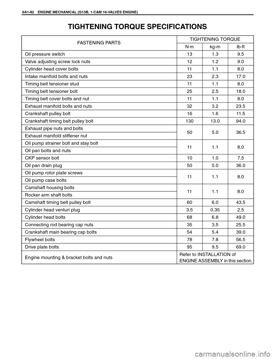
6A1-82 ENGINE MECHANICAL (G13B, 1-CAM 16-VALVES ENGINE)
TIGHTENING TORQUE SPECIFICATIONS
FASTENING PARTSTIGHTENING TORQUEFASTENING PA R T SN.mkg-mlb-ft
Oil pressure switch131.39.5
Valve adjusting screw lock nuts121.29.0
Cylinder head cover bolts111.18.0
Intake manifold bolts and nuts232.317.0
Timing belt tensioner stud111.18.0
Timing belt tensioner bolt252.518.0
Timing belt cover bolts and nut111.18.0
Exhaust manifold bolts and nuts323.223.5
Crankshaft pulley bolt161.611.5
Crankshaft timing belt pulley bolt13013.094.0
Exhaust pipe nuts and bolts505036 5Exhaust manifold stiffener nut505.036.5
Oil pump strainer bolt and stay bolt111180Oil pan bolts and nuts111.18.0
CKP sensor bolt101.07.5
Oil pan drain plug505.036.0
Oil pump rotor plate screws111180Oil pump case bolts111.18.0
Camshaft housing bolts111180Rocker arm shaft bolts111.18.0
Camshaft timing belt pulley bolt606.043.5
Cylinder head venturi plug3.50.352.5
Cylinder head bolts686.849.0
Connecting rod bearing cap nuts353.525.5
Crankshaft main bearing cap bolts545.439.0
Flywheel bolts787.856.5
Drive plate bolts959.569.0
Engine mounting & bracket bolts and nutsRefer to INSTALLATION of
ENGINE ASSEMBLY in this section.
Page 384 of 557
1. Radiator hose
2. Clamp
ENGINE COOLING 6B-7
ON-VEHICLE SERVICE
WARNING:
�Check to make sure that engine coolant temperature is
cold before removing any part of cooling system.
�Also be sure to disconnect negative cord from battery ter-
minal before removing any part.
COOLING WATER PIPES OR HOSES
REMOVAL
1) Drain cooling system.
2) To remove these pipes or hoses, loosen screw on each pipe or
hose clip and pull hose end off.
INSTALLATION
Install removed parts in reverse order of removal procedure, noting
the following.
�Tighten each clamp bolt securely.
�Refill cooling system with proper coolant, referring to description
on COOLANT of MAINTENANCE.
THERMOSTAT
REMOVAL
1) Disconnect negative cable at battery.
2) Drain cooling system and tighten drain plug.
3) Disconnect thermostat cap (1) from thermostat case (2).
Page 386 of 557

ENGINE COOLING 6B-9
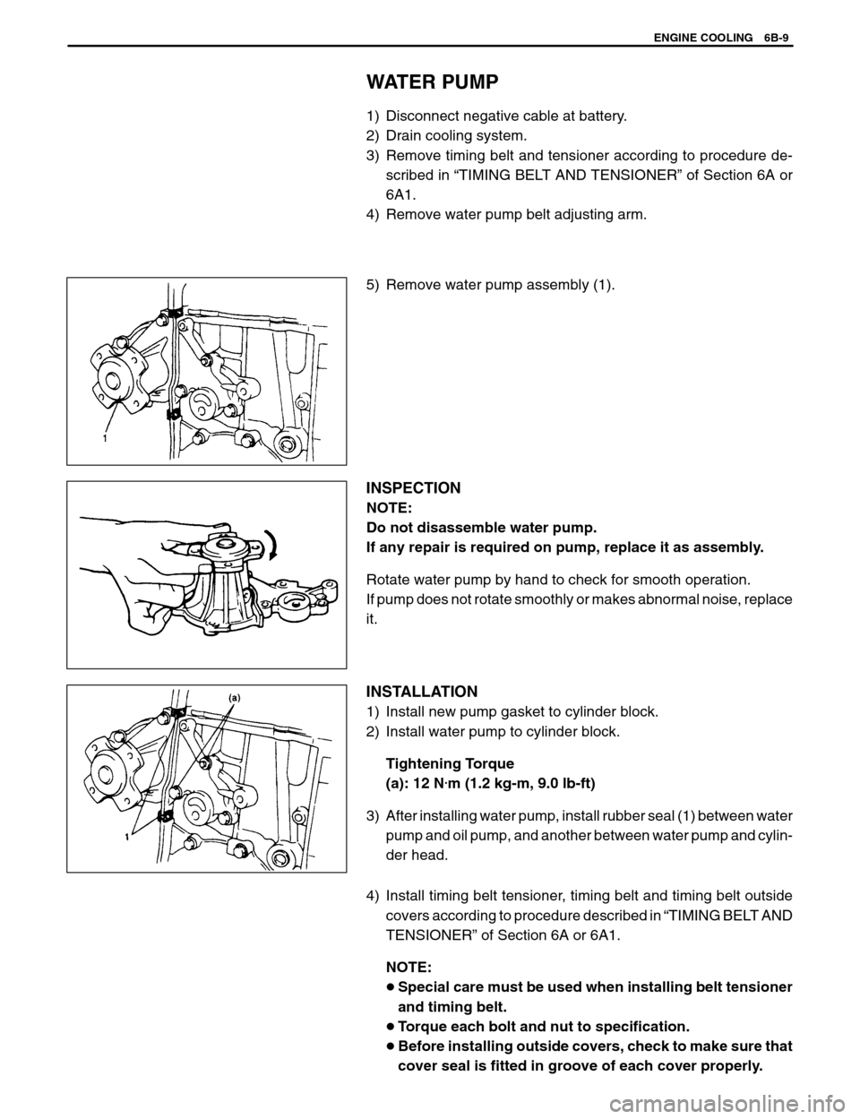
WATER PUMP
1) Disconnect negative cable at battery.
2) Drain cooling system.
3) Remove timing belt and tensioner according to procedure de-
scribed in “TIMING BELT AND TENSIONER” of Section 6A or
6A1.
4) Remove water pump belt adjusting arm.
5) Remove water pump assembly (1).
INSPECTION
NOTE:
Do not disassemble water pump.
If any repair is required on pump, replace it as assembly.
Rotate water pump by hand to check for smooth operation.
If pump does not rotate smoothly or makes abnormal noise, replace
it.
INSTALLATION
1) Install new pump gasket to cylinder block.
2) Install water pump to cylinder block.
Tightening Torque
(a): 12 N
.m (1.2 kg-m, 9.0 lb-ft)
3) After installing water pump, install rubber seal (1) between water
pump and oil pump, and another between water pump and cylin-
der head.
4) Install timing belt tensioner, timing belt and timing belt outside
covers according to procedure described in “TIMING BELT AND
TENSIONER” of Section 6A or 6A1.
NOTE:
�Special care must be used when installing belt tensioner
and timing belt.
�Torque each bolt and nut to specification.
�Before installing outside covers, check to make sure that
cover seal is fitted in groove of each cover properly.