Page 342 of 557

ENGINE MECHANICAL (G13B, 1-CAM 16-VALVES ENGINE) 6A1-47
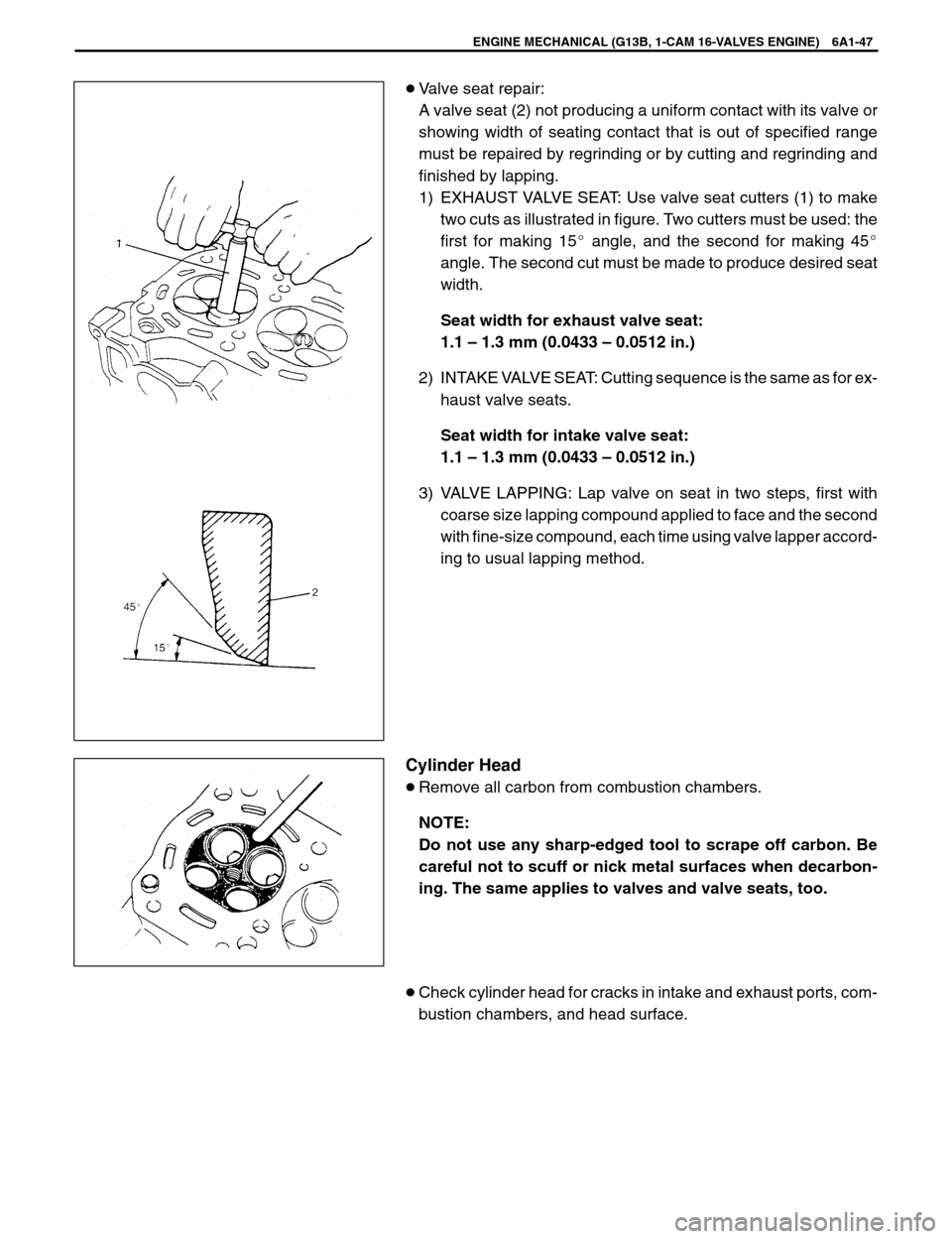
�Valve seat repair:
A valve seat (2) not producing a uniform contact with its valve or
showing width of seating contact that is out of specified range
must be repaired by regrinding or by cutting and regrinding and
finished by lapping.
1) EXHAUST VALVE SEAT: Use valve seat cutters (1) to make
two cuts as illustrated in figure. Two cutters must be used: the
first for making 15� angle, and the second for making 45�
angle. The second cut must be made to produce desired seat
width.
Seat width for exhaust valve seat:
1.1 – 1.3 mm (0.0433 – 0.0512 in.)
2) INTAKE VALVE SEAT: Cutting sequence is the same as for ex-
haust valve seats.
Seat width for intake valve seat:
1.1 – 1.3 mm (0.0433 – 0.0512 in.)
3) VALVE LAPPING: Lap valve on seat in two steps, first with
coarse size lapping compound applied to face and the second
with fine-size compound, each time using valve lapper accord-
ing to usual lapping method.
Cylinder Head
�Remove all carbon from combustion chambers.
NOTE:
Do not use any sharp-edged tool to scrape off carbon. Be
careful not to scuff or nick metal surfaces when decarbon-
ing. The same applies to valves and valve seats, too.
�Check cylinder head for cracks in intake and exhaust ports, com-
bustion chambers, and head surface.
Page 354 of 557

ENGINE MECHANICAL (G13B, 1-CAM 16-VALVES ENGINE) 6A1-59
Crank Pin and Connecting Rod Bearings
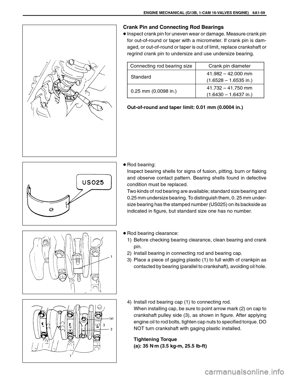
�Inspect crank pin for uneven wear or damage. Measure crank pin
for out-of-round or taper with a micrometer. If crank pin is dam-
aged, or out-of-round or taper is out of limit, replace crankshaft or
regrind crank pin to undersize and use undersize bearing.
Connecting rod bearing size
Crank pin diameter
Standard41.982 – 42.000 mm
(1.6528 – 1.6535 in.)
0.25 mm (0.0098 in.)41.732 – 41.750 mm
(1.6430 – 1.6437 in.)
Out-of-round and taper limit: 0.01 mm (0.0004 in.)
�Rod bearing:
Inspect bearing shells for signs of fusion, pitting, burn or flaking
and observe contact pattern. Bearing shells found in defective
condition must be replaced.
Two kinds of rod bearing are available; standard size bearing and
0.25 mm undersize bearing. To distinguish them, 0. 25 mm under-
size bearing has the stamped number (US025) on its backside as
indicated in figure, but standard size one has no number.
�Rod bearing clearance:
1) Before checking bearing clearance, clean bearing and crank
pin.
2) Install bearing in connecting rod and bearing cap.
3) Place a piece of gaging plastic (1) to full width of crankpin as
contacted by bearing (parallel to crankshaft), avoiding oil hole.
4) Install rod bearing cap (1) to connecting rod.
When installing cap, be sure to point arrow mark (2) on cap to
crankshaft pulley side (3), as shown in figure. After applying
engine oil to rod bolts, tighten cap nuts to specified torque. DO
NOT turn crankshaft with gaging plastic installed.
Tightening Torque
(a): 35 N
.m (3.5 kg-m, 25.5 lb-ft)
Page 355 of 557

1 or 2
Piston
No.1 Cylinder
No.2 Cylinder
No.3 Cylinder
No.4 Cylinder
Crank
pulley
side
Flywheel
side
6A1-60 ENGINE MECHANICAL (G13B, 1-CAM 16-VALVES ENGINE)
5) Remove cap and using a scale (2) on gaging plastic (1) enve-
lope, measure gaging plastic width at the widest point (clear-
ance).
If clearance exceeds its limit, use a new standard size bearing
and remeasure clearance.
Item
StandardLimit
Bearing
clearance0.020 – 0.050 mm
(0.0008 – 0.0019 in.)0.080 mm
(0.0031 in.)
6) If clearance can not be brought to within its limit even by using
a new standard size bearing, regrind crankpin to undersize
and use 0.25 mm undersize bearing.
ASSEMBLY
NOTE:
Two sizes of piston are available as standard size spare part
so as to ensure proper piston-to-cylinder clearance. When
installing a standard size piston, make sure to match piston
with cylinder as follows.
a) Each piston has stamped number 1 or 2 as shown. It represents
outer diameter of piston.
b) There are also stamped numbers of 1 and 2 on the cylinder block
as shown. The first number represents inner diameter of No.1
cylinder, the second number of No.2 cylinder, the third number
of No.3 cylinder and the fourth number of No.4 cylinder.
Page 366 of 557

1. Gaging plastic
ENGINE MECHANICAL (G13B, 1-CAM 16-VALVES ENGINE) 6A1-71
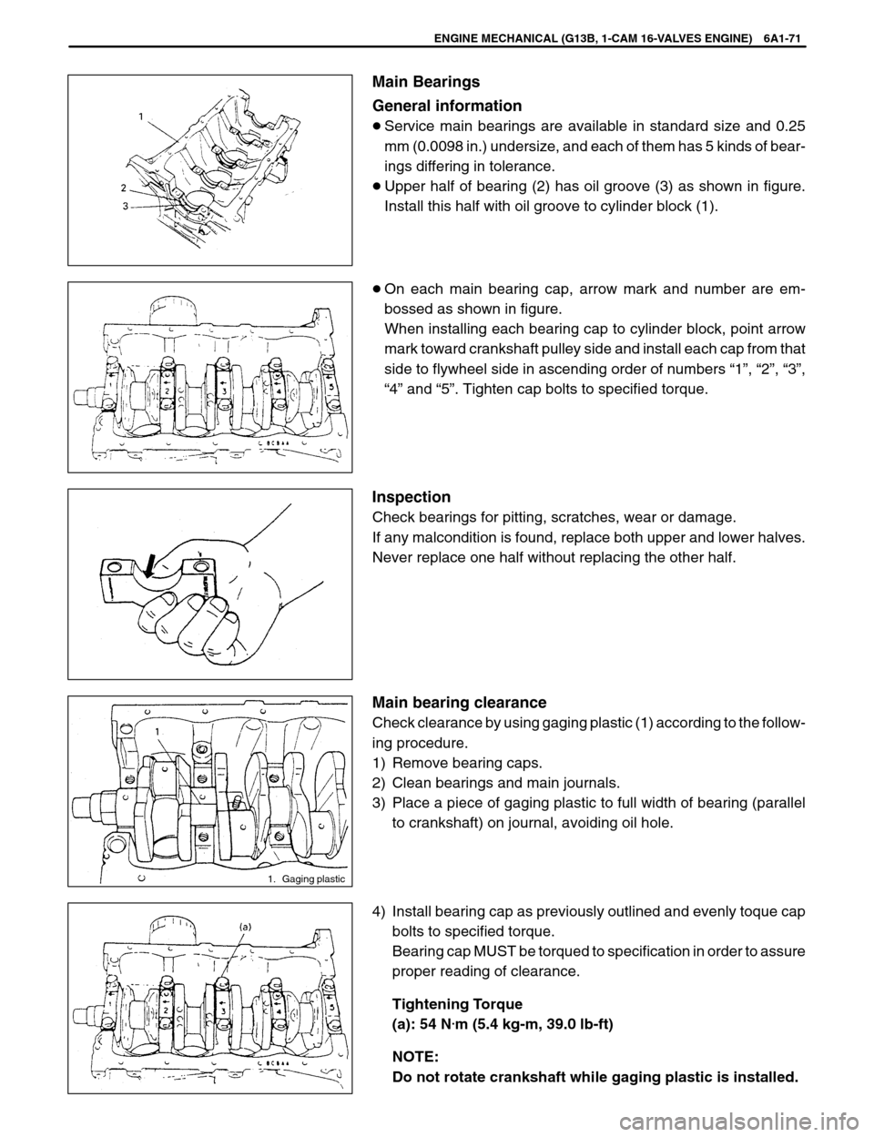
Main Bearings
General information
�Service main bearings are available in standard size and 0.25
mm (0.0098 in.) undersize, and each of them has 5 kinds of bear-
ings differing in tolerance.
�Upper half of bearing (2) has oil groove (3) as shown in figure.
Install this half with oil groove to cylinder block (1).
�On each main bearing cap, arrow mark and number are em-
bossed as shown in figure.
When installing each bearing cap to cylinder block, point arrow
mark toward crankshaft pulley side and install each cap from that
side to flywheel side in ascending order of numbers “1”, “2”, “3”,
“4” and “5”. Tighten cap bolts to specified torque.
Inspection
Check bearings for pitting, scratches, wear or damage.
If any malcondition is found, replace both upper and lower halves.
Never replace one half without replacing the other half.
Main bearing clearance
Check clearance by using gaging plastic (1) according to the follow-
ing procedure.
1) Remove bearing caps.
2) Clean bearings and main journals.
3) Place a piece of gaging plastic to full width of bearing (parallel
to crankshaft) on journal, avoiding oil hole.
4) Install bearing cap as previously outlined and evenly toque cap
bolts to specified torque.
Bearing cap MUST be torqued to specification in order to assure
proper reading of clearance.
Tightening Torque
(a): 54 N
.m (5.4 kg-m, 39.0 lb-ft)
NOTE:
Do not rotate crankshaft while gaging plastic is installed.
Page 367 of 557

6A1-72 ENGINE MECHANICAL (G13B, 1-CAM 16-VALVES ENGINE)
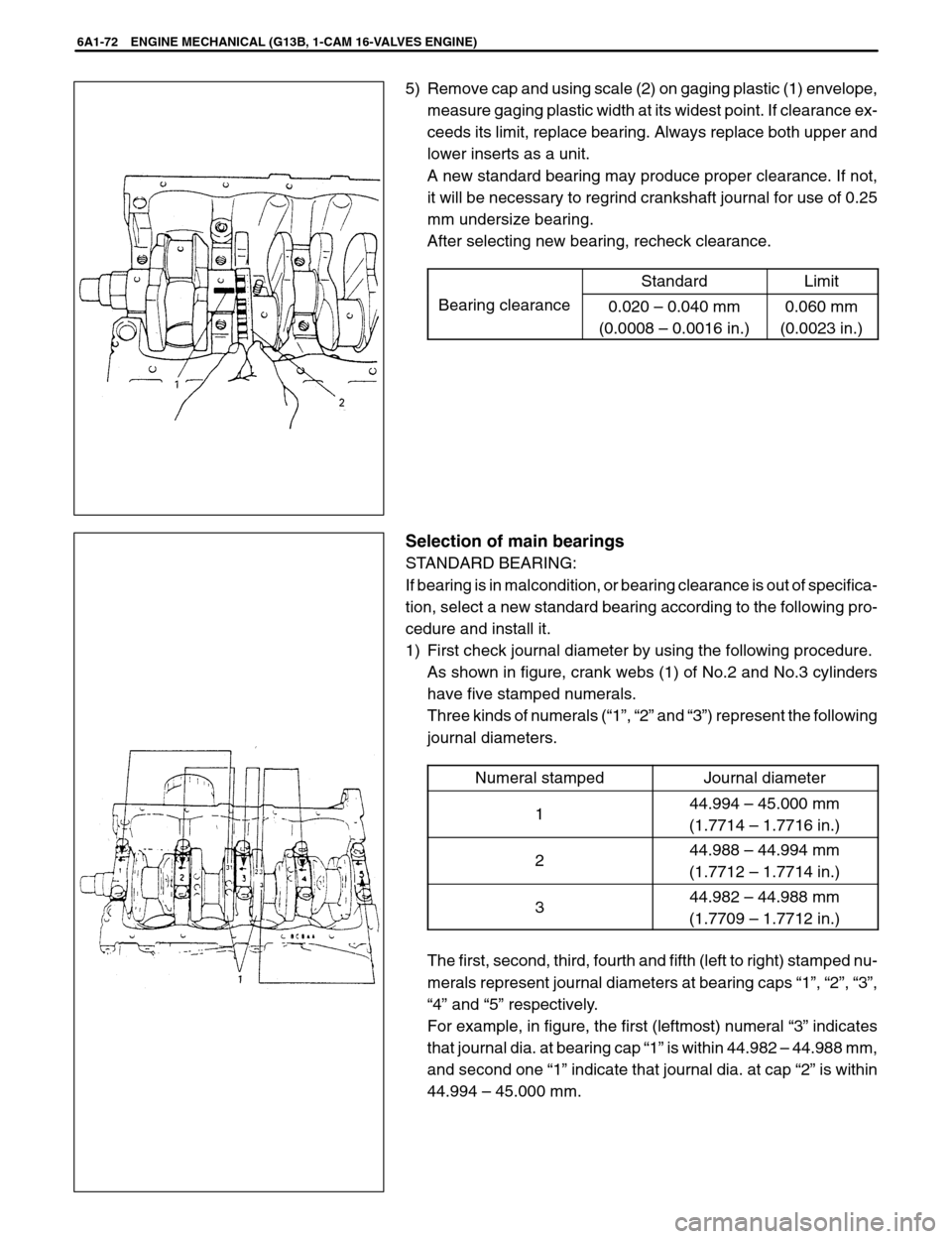
5) Remove cap and using scale (2) on gaging plastic (1) envelope,
measure gaging plastic width at its widest point. If clearance ex-
ceeds its limit, replace bearing. Always replace both upper and
lower inserts as a unit.
A new standard bearing may produce proper clearance. If not,
it will be necessary to regrind crankshaft journal for use of 0.25
mm undersize bearing.
After selecting new bearing, recheck clearance.
StandardLimit
Bearing clearance0.020 – 0.040 mm
(0.0008 – 0.0016 in.)0.060 mm
(0.0023 in.)
Selection of main bearings
STANDARD BEARING:
If bearing is in malcondition, or bearing clearance is out of specifica-
tion, select a new standard bearing according to the following pro-
cedure and install it.
1) First check journal diameter by using the following procedure.
As shown in figure, crank webs (1) of No.2 and No.3 cylinders
have five stamped numerals.
Three kinds of numerals (“1”, “2” and “3”) represent the following
journal diameters.
Numeral stamped
Journal diameter
144.994 – 45.000 mm
(1.7714 – 1.7716 in.)
244.988 – 44.994 mm
(1.7712 – 1.7714 in.)
344.982 – 44.988 mm
(1.7709 – 1.7712 in.)
The first, second, third, fourth and fifth (left to right) stamped nu-
merals represent journal diameters at bearing caps “1”, “2”, “3”,
“4” and “5” respectively.
For example, in figure, the first (leftmost) numeral “3” indicates
that journal dia. at bearing cap “1” is within 44.982 – 44.988 mm,
and second one “1” indicate that journal dia. at cap “2” is within
44.994 – 45.000 mm.