Page 643 of 698

6E1-22 ENGINE AND EMISSION CONTROL SYSTEM
6) Start engine and warm it up to normal operating tempera-
ture.
7) Measure fuel pressure at idling.
If measured pressure does not satisfy specification, refer to
“Diagnostic Flow Table B-3” in “Engine Diagnosis” section
and check each possibly defective part. Replace if found
defective.
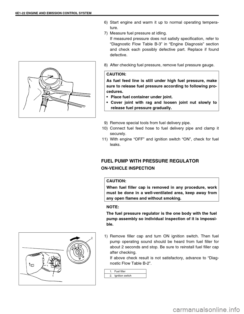
8) After checking fuel pressure, remove fuel pressure gauge.
9) Remove special tools from fuel delivery pipe.
10) Connect fuel feed hose to fuel delivery pipe and clamp it
securely.
11) With engine “OFF” and ignition switch “ON”, check for fuel
leaks.
FUEL PUMP WITH PRESSURE REGULATOR
ON-VEHICLE INSPECTION
1) Remove filler cap and turn ON ignition switch. Then fuel
pump operating sound should be heard from fuel filler for
about 2 seconds and stop. Be sure to reinstall fuel filler cap
after checking.
If above check result is not satisfactory, advance to “Diag-
nostic Flow Table B-2”. CAUTION:
As fuel feed line is still under high fuel pressure, make
sure to release fuel pressure according to following pro-
cedures.
Place fuel container under joint.
Cover joint with rag and loosen joint nut slowly to
release fuel pressure gradually.
CAUTION:
When fuel filler cap is removed in any procedure, work
must be done in a well-ventilated area, keep away from
any open flames and without smoking.
NOTE:
The fuel pressure regulator is the one body with the fuel
pump assembly so individual inspection of it is impossi-
ble.
1. Fuel filler
2. Ignition switch
Page 655 of 698

6E1-34 ENGINE AND EMISSION CONTROL SYSTEM
FUEL CUT OPERATION
INSPECTION
1) Warm up engine to normal operating temperature.
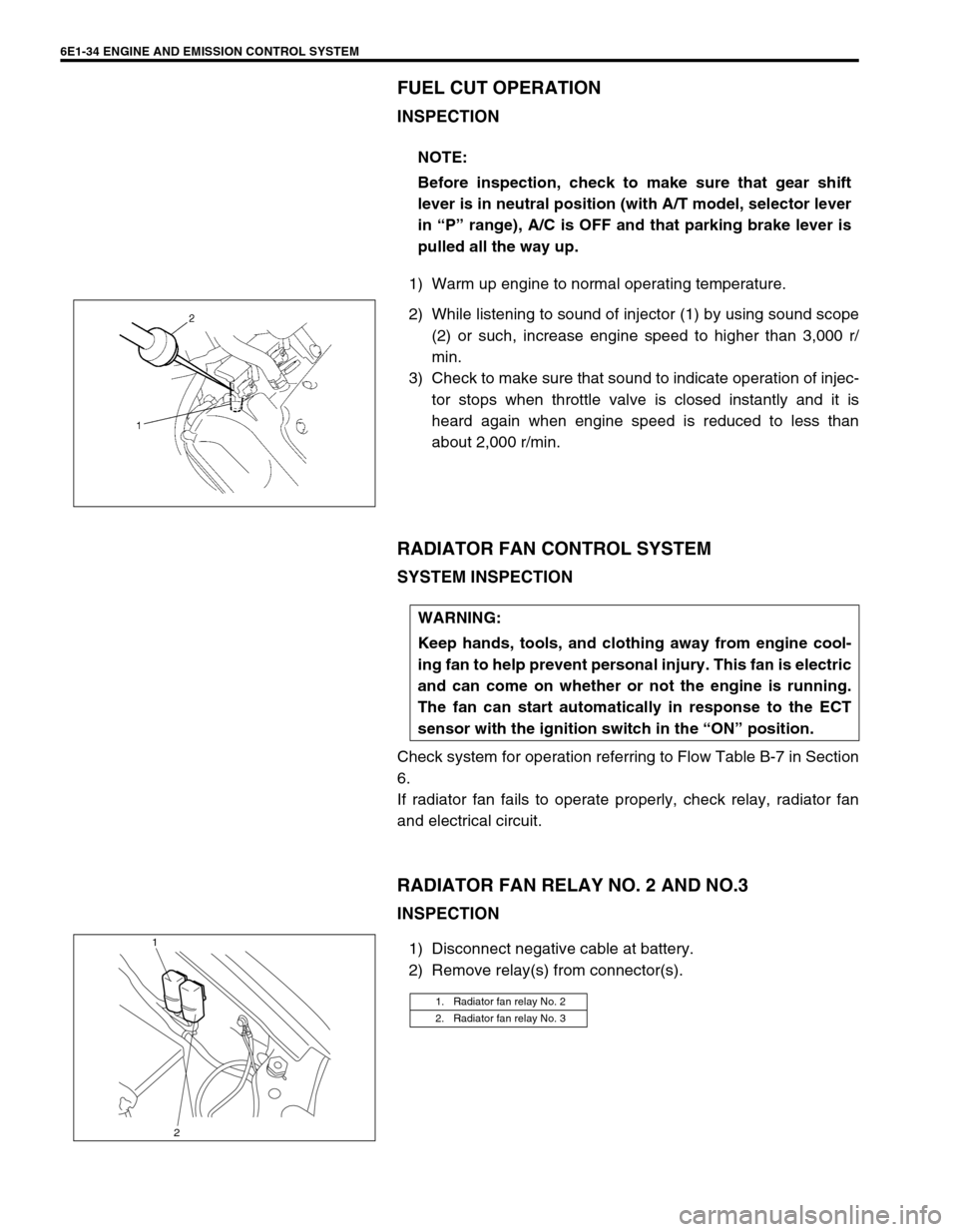
2) While listening to sound of injector (1) by using sound scope
(2) or such, increase engine speed to higher than 3,000 r/
min.
3) Check to make sure that sound to indicate operation of injec-
tor stops when throttle valve is closed instantly and it is
heard again when engine speed is reduced to less than
about 2,000 r/min.
RADIATOR FAN CONTROL SYSTEM
SYSTEM INSPECTION
Check system for operation referring to Flow Table B-7 in Section
6.
If radiator fan fails to operate properly, check relay, radiator fan
and electrical circuit.
RADIATOR FAN RELAY NO. 2 AND NO.3
INSPECTION
1) Disconnect negative cable at battery.
2) Remove relay(s) from connector(s).NOTE:
Before inspection, check to make sure that gear shift
lever is in neutral position (with A/T model, selector lever
in “P” range), A/C is OFF and that parking brake lever is
pulled all the way up.
WARNING:
Keep hands, tools, and clothing away from engine cool-
ing fan to help prevent personal injury. This fan is electric
and can come on whether or not the engine is running.
The fan can start automatically in response to the ECT
sensor with the ignition switch in the “ON” position.
1. Radiator fan relay No. 2
2. Radiator fan relay No. 3
1
2
Page 659 of 698

6E1-38 ENGINE AND EMISSION CONTROL SYSTEM
3) Connect purge hose to EVAP canister and warm up engine
to normal operating temperature.
4) Disconnect purge hose from EVAP canister.
5) Also check that vacuum is felt when engine is running at idle
speed.
If check result is not satisfactory, check vacuum passage,
hoses, EVAP canister purge valve, wire harness and ECM.
VACUUM PASSAGE INSPECTION
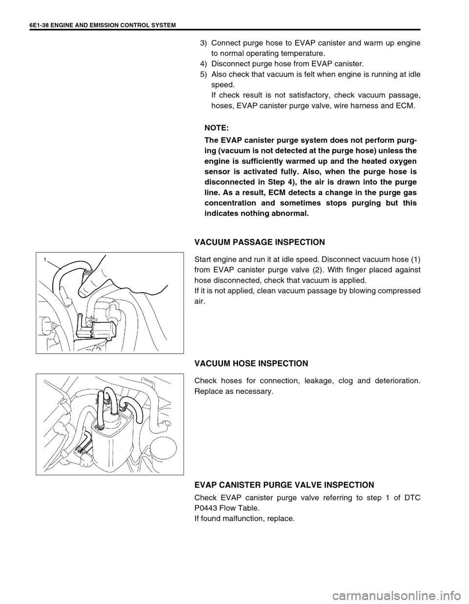
Start engine and run it at idle speed. Disconnect vacuum hose (1)
from EVAP canister purge valve (2). With finger placed against
hose disconnected, check that vacuum is applied.
If it is not applied, clean vacuum passage by blowing compressed
air.
VACUUM HOSE INSPECTION
Check hoses for connection, leakage, clog and deterioration.
Replace as necessary.
EVAP CANISTER PURGE VALVE INSPECTION
Check EVAP canister purge valve referring to step 1 of DTC
P0443 Flow Table.
If found malfunction, replace.NOTE:
The EVAP canister purge system does not perform purg-
ing (vacuum is not detected at the purge hose) unless the
engine is sufficiently warmed up and the heated oxygen
sensor is activated fully. Also, when the purge hose is
disconnected in Step 4), the air is drawn into the purge
line. As a result, ECM detects a change in the purge gas
concentration and sometimes stops purging but this
indicates nothing abnormal.
Page 675 of 698

CRANKING SYSTEM 6G-3
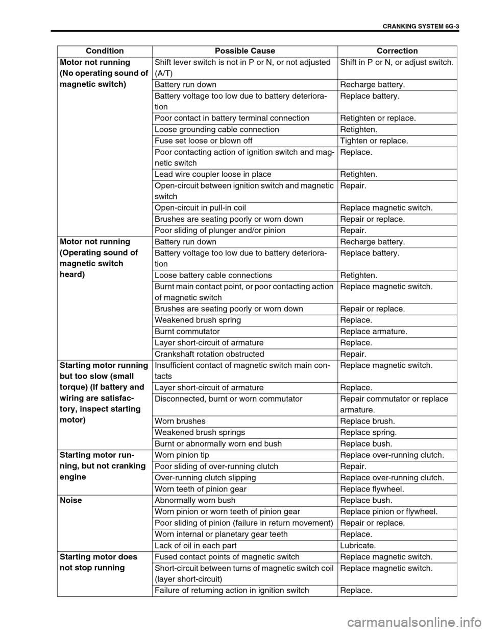
Condition Possible Cause Correction
Motor not running
(No operating sound of
magnetic switch)Shift lever switch is not in P or N, or not adjusted
(A/T)Shift in P or N, or adjust switch.
Battery run down Recharge battery.
Battery voltage too low due to battery deteriora-
tionReplace battery.
Poor contact in battery terminal connection Retighten or replace.
Loose grounding cable connection Retighten.
Fuse set loose or blown off Tighten or replace.
Poor contacting action of ignition switch and mag-
netic switchReplace.
Lead wire coupler loose in place Retighten.
Open-circuit between ignition switch and magnetic
switchRepair.
Open-circuit in pull-in coil Replace magnetic switch.
Brushes are seating poorly or worn down Repair or replace.
Poor sliding of plunger and/or pinion Repair.
Motor not running
(Operating sound of
magnetic switch
heard)Battery run down Recharge battery.
Battery voltage too low due to battery deteriora-
tionReplace battery.
Loose battery cable connections Retighten.
Burnt main contact point, or poor contacting action
of magnetic switchReplace magnetic switch.
Brushes are seating poorly or worn down Repair or replace.
Weakened brush spring Replace.
Burnt commutator Replace armature.
Layer short-circuit of armature Replace.
Crankshaft rotation obstructed Repair.
Starting motor running
but too slow (small
torque) (If battery and
wiring are satisfac-
tory, inspect starting
motor)Insufficient contact of magnetic switch main con-
tactsReplace magnetic switch.
Layer short-circuit of armature Replace.
Disconnected, burnt or worn commutator Repair commutator or replace
armature.
Worn brushes Replace brush.
Weakened brush springs Replace spring.
Burnt or abnormally worn end bush Replace bush.
Starting motor run-
ning, but not cranking
engineWorn pinion tip Replace over-running clutch.
Poor sliding of over-running clutch Repair.
Over-running clutch slipping Replace over-running clutch.
Worn teeth of pinion gear Replace flywheel.
Noise
Abnormally worn bush Replace bush.
Worn pinion or worn teeth of pinion gear Replace pinion or flywheel.
Poor sliding of pinion (failure in return movement) Repair or replace.
Worn internal or planetary gear teeth Replace.
Lack of oil in each part Lubricate.
Starting motor does
not stop runningFused contact points of magnetic switch Replace magnetic switch.
Short-circuit between turns of magnetic switch coil
(layer short-circuit)Replace magnetic switch.
Failure of returning action in ignition switch Replace.