2000 SUZUKI SWIFT stop start
[x] Cancel search: stop startPage 37 of 698
0B-8 MAINTENANCE AND LUBRICATION
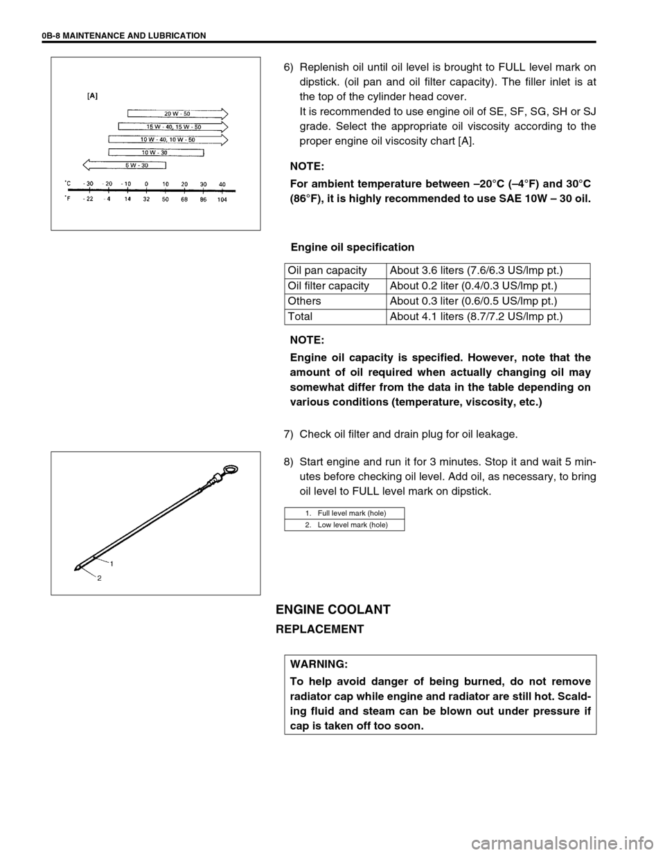
6) Replenish oil until oil level is brought to FULL level mark on
dipstick. (oil pan and oil filter capacity). The filler inlet is at
the top of the cylinder head cover.
It is recommended to use engine oil of SE, SF, SG, SH or SJ
grade. Select the appropriate oil viscosity according to the
proper engine oil viscosity chart [A].
Engine oil specification
7) Check oil filter and drain plug for oil leakage.
8) Start engine and run it for 3 minutes. Stop it and wait 5 min-
utes before checking oil level. Add oil, as necessary, to bring
oil level to FULL level mark on dipstick.
ENGINE COOLANT
REPLACEMENT
NOTE:
For ambient temperature between –20°C (–4°F) and 30°C
(86°F), it is highly recommended to use SAE 10W – 30 oil.
Oil pan capacity About 3.6 liters (7.6/6.3 US/lmp pt.)
Oil filter capacity About 0.2 liter (0.4/0.3 US/lmp pt.)
Others About 0.3 liter (0.6/0.5 US/lmp pt.)
Total About 4.1 liters (8.7/7.2 US/lmp pt.)
NOTE:
Engine oil capacity is specified. However, note that the
amount of oil required when actually changing oil may
somewhat differ from the data in the table depending on
various conditions (temperature, viscosity, etc.)
1. Full level mark (hole)
2. Low level mark (hole)
WARNING:
To help avoid danger of being burned, do not remove
radiator cap while engine and radiator are still hot. Scald-
ing fluid and steam can be blown out under pressure if
cap is taken off too soon.
Page 49 of 698

0B-20 MAINTENANCE AND LUBRICATION
ENGINE START
Check engine start for readiness.
On automatic transmission vehicles, try to start the engine in each select lever position. The starting motor
should crank only in “P” (Park) or “N” (Neutral).
On manual transmission vehicles, place the shift lever in “Neutral,” depress clutch pedal fully any try to start.
EXHAUST SYSTEM CHECK
Check for leakage, cracks or loose supports.
CLUTCH (FOR MANUAL TRANSMISSION)
Check for the following.
Clutch is completely released when depressing clutch pedal,
No slipping clutch occurs when releasing pedal and accelerating.
Clutch itself is free from any abnormal condition.
GEARSHIFT OR SELECT LEVER (TRANSMISSION)
Check gear shift or select lever for smooth shifting to all positions and for good performance of transmission in
any position.
With automatic transmission equipped vehicle, also check that shift indicator indicates properly according to
which position select lever is shifted to.
With automatic transmission equipped vehicle, make sure that vehicle is at complete stop when shifting select
lever to “P” range position and release all brakes.
BRAKE
Foot Brake
Check the followings:
that brake pedal has proper travel,
that brake works properly,
that it is free from noise,
that vehicle does not pull to one side when brake is applied.
and that brake do not drag.
Parking Brake
Check that lever has proper travel.
Check to ensure that parking brake is fully effective when the vehicle is stopped on the safe slope and brake
lever is pulled all the way.WARNING:
Before performing the following check, be sure to have enough room around the vehicle. Then, firmly
apply both the parking brake and the regular brakes. Do not use the accelerator pedal. If the engine
starts, be ready to turn off the ignition promptly. Take these precautions because the vehicle could
move without warning and possibly cause personal injury or property damage.
WARNING:
With vehicle parked on a fairly steep slope, make sure nothing is in the way downhill to avoid any per-
sonal injury or property damage. Be prepared to apply regular brake quickly even if vehicle should
start to move.
Page 85 of 698
1B-20 AIR CONDITIONING (OPTIONAL)
REFRIGERANT RECOVERY, EVACUATING AND CHARGING
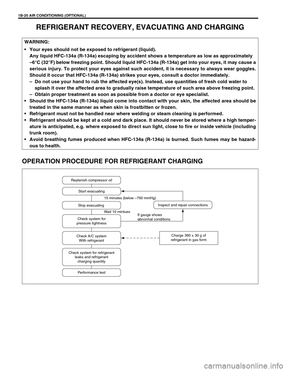
OPERATION PROCEDURE FOR REFRIGERANT CHARGING
WARNING:
Your eyes should not be exposed to refrigerant (liquid).
Any liquid HFC-134a (R-134a) escaping by accident shows a temperature as low as approximately
–6°C (32°F) below freezing point. Should liquid HFC-134a (R-134a) get into your eyes, it may cause a
serious injury. To protect your eyes against such accident, it is necessary to always wear goggles.
Should it occur that HFC-134a (R-134a) strikes your eyes, consult a doctor immediately.
– Do not use your hand to rub the affected eye(s). Instead, use quantities of fresh cold water to
splash it over the affected area to gradually raise temperature of such area above freezing point.
– Obtain proper treatment as soon as possible from a doctor or eye specialist.
Should the HFC-134a (R-134a) liquid come into contact with your skin, the affected area should be
treated in the same manner as when skin is frostbitten or frozen.
Refrigerant must not be handled near where welding or steam cleaning is performed.
Refrigerant should be kept at a cold and dark place. It should never be stored where a high temper-
ature is anticipated, e.g. where exposed to direct sun light, close to fire or inside vehicle (including
trunk room).
Avoid breathing fumes produced when HFC-134a (R-134a) is burned. Such fumes may be hazard-
ous to health.
Replenish compressor oil
Start evacuating
Inspect and repair connections
Charge 360 ± 30 g of
refrigerant in gas form Stop evacuating 15 minutes (below –760 mmHg)
Wait 10 mintues
If gauge shows
abnormal conditions Check system for
pressure tightness
Check A/C system
With refrigerant
Check system for refrigerant
leaks and refrigerant
charging quantity
Performance test
Page 89 of 698
1B-24 AIR CONDITIONING (OPTIONAL)
CHARGING
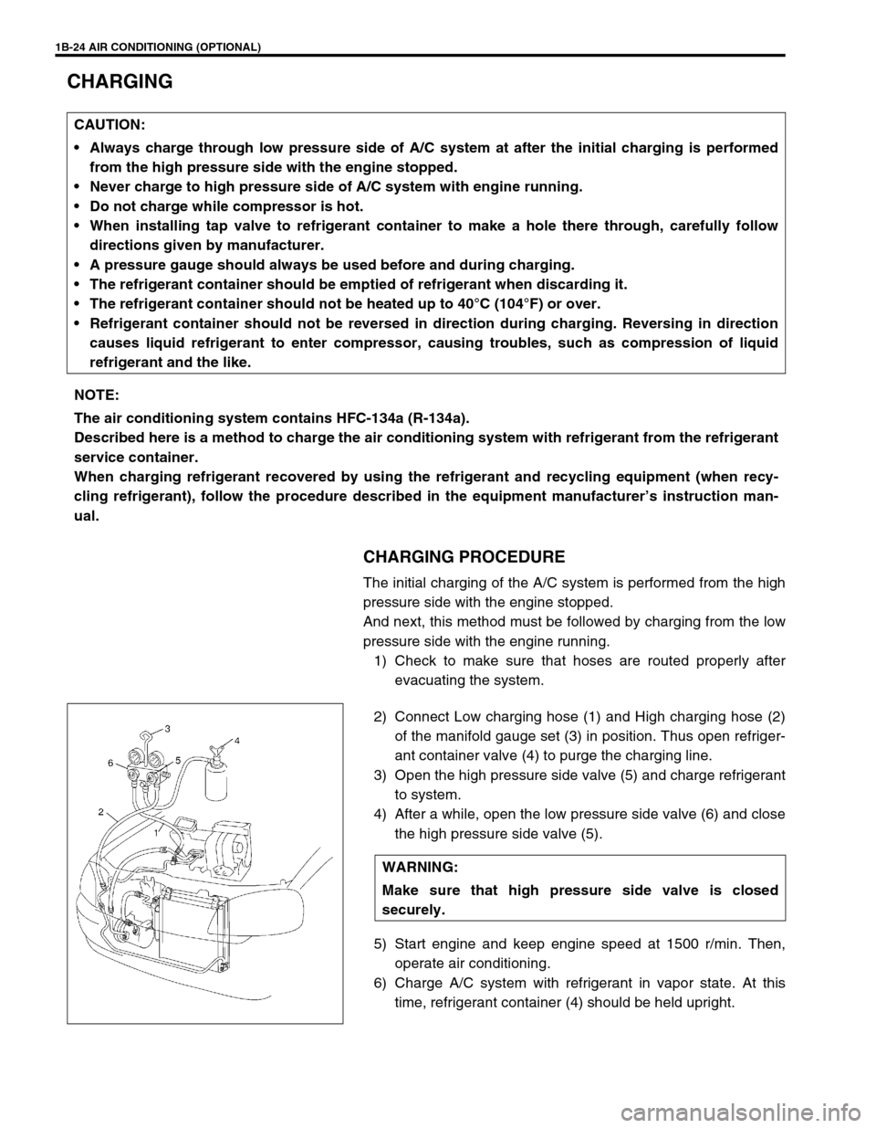
CHARGING PROCEDURE
The initial charging of the A/C system is performed from the high
pressure side with the engine stopped.
And next, this method must be followed by charging from the low
pressure side with the engine running.
1) Check to make sure that hoses are routed properly after
evacuating the system.
2) Connect Low charging hose (1) and High charging hose (2)
of the manifold gauge set (3) in position. Thus open refriger-
ant container valve (4) to purge the charging line.
3) Open the high pressure side valve (5) and charge refrigerant
to system.
4) After a while, open the low pressure side valve (6) and close
the high pressure side valve (5).
5) Start engine and keep engine speed at 1500 r/min. Then,
operate air conditioning.
6) Charge A/C system with refrigerant in vapor state. At this
time, refrigerant container (4) should be held upright. CAUTION:
Always charge through low pressure side of A/C system at after the initial charging is performed
from the high pressure side with the engine stopped.
Never charge to high pressure side of A/C system with engine running.
Do not charge while compressor is hot.
When installing tap valve to refrigerant container to make a hole there through, carefully follow
directions given by manufacturer.
A pressure gauge should always be used before and during charging.
The refrigerant container should be emptied of refrigerant when discarding it.
The refrigerant container should not be heated up to 40°C (104°F) or over.
Refrigerant container should not be reversed in direction during charging. Reversing in direction
causes liquid refrigerant to enter compressor, causing troubles, such as compression of liquid
refrigerant and the like.
NOTE:
The air conditioning system contains HFC-134a (R-134a).
Described here is a method to charge the air conditioning system with refrigerant from the refrigerant
service container.
When charging refrigerant recovered by using the refrigerant and recycling equipment (when recy-
cling refrigerant), follow the procedure described in the equipment manufacturer’s instruction man-
ual.
WARNING:
Make sure that high pressure side valve is closed
securely.
Page 145 of 698

3B1-4 ELECTRICAL POWER STEERING (P/S) SYSTEM
DIAGNOSIS
The P/S system in this vehicle is controlled by P/S control module. P/S control module has an on-board diagnos-
tic system which detects a malfunction in this system.
When diagnosing troubles, be sure to have full understanding of the outline of “ON-BOARD DIAGNOSTIC SYS-
TEM” and each item in “PRECAUTION IN DIAGNOSING TROUBLE” and execute diagnosis according to “SYS-
TEM CHECK FLOW TABLE”.
ON-BOARD DIAGNOSTIC SYSTEM
P/S control module performs on-board diagnosis (self-diagnosis)
on the system and operates “EPS” warning lamp (1) (malfunction
indicator lamp) as follows.
Malfunction indicator lamp (“EPS” warning lamp) lights when
the ignition switch is turned to ON position (but the engine at
stop) regardless of the condition of P/S control system. This
is only to check the malfunction indicator lamp (“EPS” warn-
ing lamp) bulb and its circuit.
If the areas monitored by P/S control module is free from any
trouble after the engine start (while engine is running), mal-
function indicator lamp (“EPS” warning lamp) turns OFF.
When P/S control module detects a trouble which has
occurred in the areas it monitors, malfunction indicator lamp
(“EPS” warning lamp) turns ON while the engine is running
to warn the driver of such occurrence of trouble and at the
same time it stores the exact trouble area in memory inside
of P/S control module.
PRECAUTIONS IN DIAGNOSING TROUBLES
Take a note of DTC indicated first.
Be sure to read “PRECAUTIONS FOR ELECTRONIC CIRCUIT SERVICE” in Section 0A before inspection
and observe what is written there.
When two or more troubles have occurred, their DTCs are indicated 3 times each starting with the smallest
code number and up.
DTC C1122 (DTC No.22) (engine speed signal failure) is indicated when ignition switch is ON position and
engine is not running but if indication changes to a normal one when engine is started, it means nothing
abnormal.
As DTC is stored in memory of P/S control module, be sure to clear memory after repair by performing the
procedure described in “DTC CLEARANCE”.
1
Page 169 of 698
3B1-28 ELECTRICAL POWER STEERING (P/S) SYSTEM
STEERING WHEEL PLAY INSPECTION
Check steering wheel for looseness or rattle by trying to move it in
its shaft direction and lateral direction.
If found defective, repair or replace.
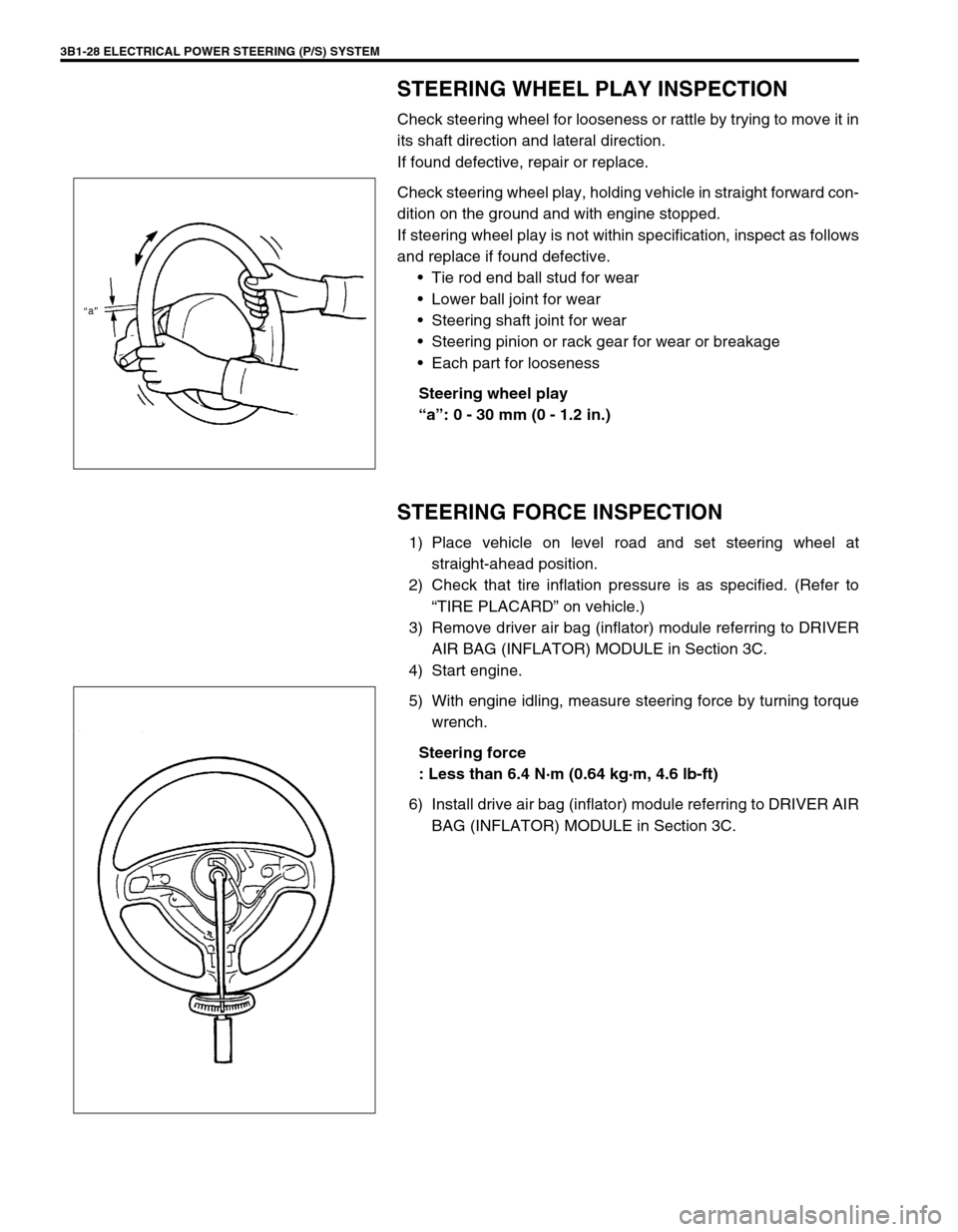
Check steering wheel play, holding vehicle in straight forward con-
dition on the ground and with engine stopped.
If steering wheel play is not within specification, inspect as follows
and replace if found defective.
Tie rod end ball stud for wear
Lower ball joint for wear
Steering shaft joint for wear
Steering pinion or rack gear for wear or breakage
Each part for looseness
Steering wheel play
“a”: 0 - 30 mm (0 - 1.2 in.)
STEERING FORCE INSPECTION
1) Place vehicle on level road and set steering wheel at
straight-ahead position.
2) Check that tire inflation pressure is as specified. (Refer to
“TIRE PLACARD” on vehicle.)
3) Remove driver air bag (inflator) module referring to DRIVER
AIR BAG (INFLATOR) MODULE in Section 3C.
4) Start engine.
5) With engine idling, measure steering force by turning torque
wrench.
Steering force
: Less than 6.4 N·m (0.64 kg·m, 4.6 lb-ft)
6) Install drive air bag (inflator) module referring to DRIVER AIR
BAG (INFLATOR) MODULE in Section 3C.
Page 284 of 698
BRAKES 5-11
Parking brake stroke (When lever is pulled up at 200 N (20
kg, 44 lbs)
: 4 to 9 notches
BOOSTER OPERATION INSPECTION
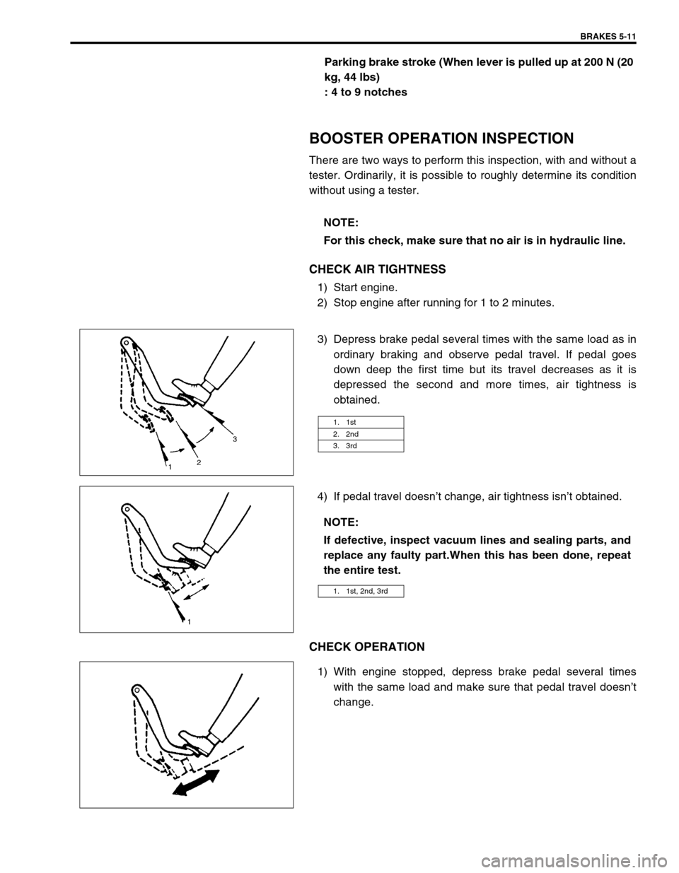
There are two ways to perform this inspection, with and without a
tester. Ordinarily, it is possible to roughly determine its condition
without using a tester.
CHECK AIR TIGHTNESS
1) Start engine.
2) Stop engine after running for 1 to 2 minutes.
3) Depress brake pedal several times with the same load as in
ordinary braking and observe pedal travel. If pedal goes
down deep the first time but its travel decreases as it is
depressed the second and more times, air tightness is
obtained.
4) If pedal travel doesn’t change, air tightness isn’t obtained.
CHECK OPERATION
1) With engine stopped, depress brake pedal several times
with the same load and make sure that pedal travel doesn’t
change. NOTE:
For this check, make sure that no air is in hydraulic line.
1. 1st
2. 2nd
3. 3rd
NOTE:
If defective, inspect vacuum lines and sealing parts, and
replace any faulty part.When this has been done, repeat
the entire test.
1. 1st, 2nd, 3rd
Page 285 of 698

5-12 BRAKES
2) Start engine while depressing brake pedal. If pedal travel
increases a little, operation is satisfactory. But no change in
pedal travel indicates malfunction.
CHECK AIR TIGHTNESS UNDER LOAD
1) With engine running, depress brake pedal. Then stop engine
while holding brake pedal depressed.
2) Hold brake pedal depressed for 30 seconds. If pedal height
does not change, condition is good. But it isn’t if pedal rises.
FLUID PRESSURE TEST (IF EQUIPPED WITH
LSPV)
Test procedure for LSPV assembly is as follows.
Before testing, confirm the following.
Fuel tank is filled with fuel fully.
Vehicle is equipped with spare tire, tools, jack and jack han-
dle.
H: Hold
H: Hold
T: 30 seconds