Page 440 of 698
ENGINE GENERAL INFORMATION AND DIAGNOSIS 6-71
INSPECTION
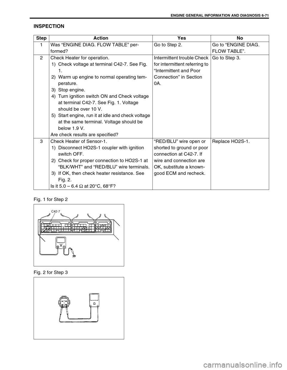
Fig. 1 for Step 2
Fig. 2 for Step 3Step Action Yes No
1Was “ENGINE DIAG. FLOW TABLE” per-
formed?Go to Step 2. Go to “ENGINE DIAG.
FLOW TABLE”.
2 Check Heater for operation.
1) Check voltage at terminal C42-7. See Fig.
1.
2) Warm up engine to normal operating tem-
perature.
3) Stop engine.
4) Turn ignition switch ON and Check voltage
at terminal C42-7. See Fig. 1. Voltage
should be over 10 V.
5) Start engine, run it at idle and check voltage
at the same terminal. Voltage should be
below 1.9 V.
Are check results are specified?Intermittent trouble Check
for intermittent referring to
“Intermittent and Poor
Connection” in Section
0A.Go to Step 3.
3 Check Heater of Sensor-1.
1) Disconnect HO2S-1 coupler with ignition
switch OFF.
2) Check for proper connection to HO2S-1 at
“BLK/WHT” and “RED/BLU” wire terminals.
3) If OK, then check heater resistance. See
Fig. 2.
Is it 5.0 – 6.4 Ω at 20°C, 68°F?“RED/BLU” wire open or
shorted to ground or poor
connection at C42-7. If
wire and connection are
OK, substitute a known-
good ECM and recheck.Replace HO2S-1.
Page 443 of 698
6-74 ENGINE GENERAL INFORMATION AND DIAGNOSIS
DTC P0141 HEATED OXYGEN SENSOR (HO2S) HEATER CIRCUIT MALFUNC-
TION (SENSOR-2)
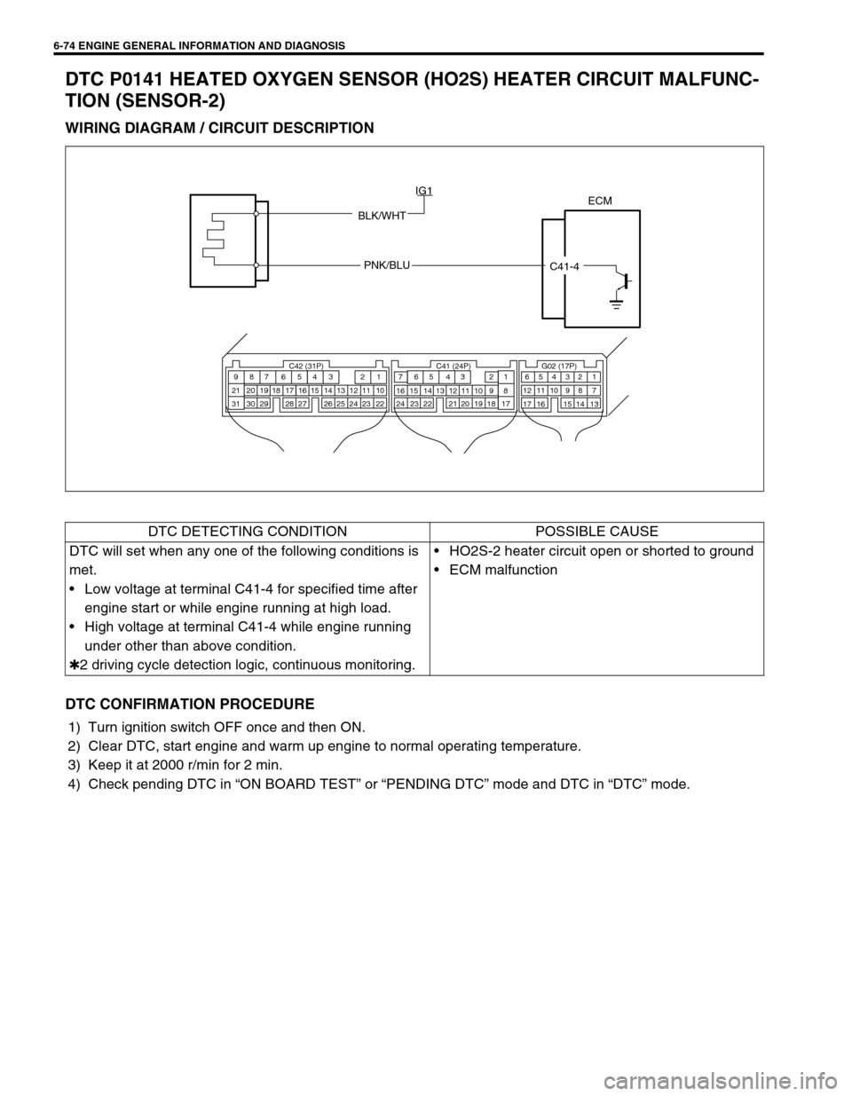
WIRING DIAGRAM / CIRCUIT DESCRIPTION
DTC CONFIRMATION PROCEDURE
1) Turn ignition switch OFF once and then ON.
2) Clear DTC, start engine and warm up engine to normal operating temperature.
3) Keep it at 2000 r/min for 2 min.
4) Check pending DTC in “ON BOARD TEST” or “PENDING DTC” mode and DTC in “DTC” mode.
ECM
BLK/WHT
PNK/BLU
C41-4 IG1
C42 (31P) C41 (24P) G02 (17P)1 2 3 4 5 6 7 8 9
10 11 12 13 14 15 16 17 18 19 20 21
22 23 24 25 26 28 27 29 30 315 6
1 2 3 4 5 6 7
11 12
9 10 11 13 12 14 15 16
16 171 2
7 8
13 14 3 4
9 10
15 17 188
19 20 21 22 23 24
DTC DETECTING CONDITION POSSIBLE CAUSE
DTC will set when any one of the following conditions is
met.
Low voltage at terminal C41-4 for specified time after
engine start or while engine running at high load.
High voltage at terminal C41-4 while engine running
under other than above condition.
✱2 driving cycle detection logic, continuous monitoring.HO2S-2 heater circuit open or shorted to ground
ECM malfunction
Page 444 of 698
ENGINE GENERAL INFORMATION AND DIAGNOSIS 6-75
INSPECTION
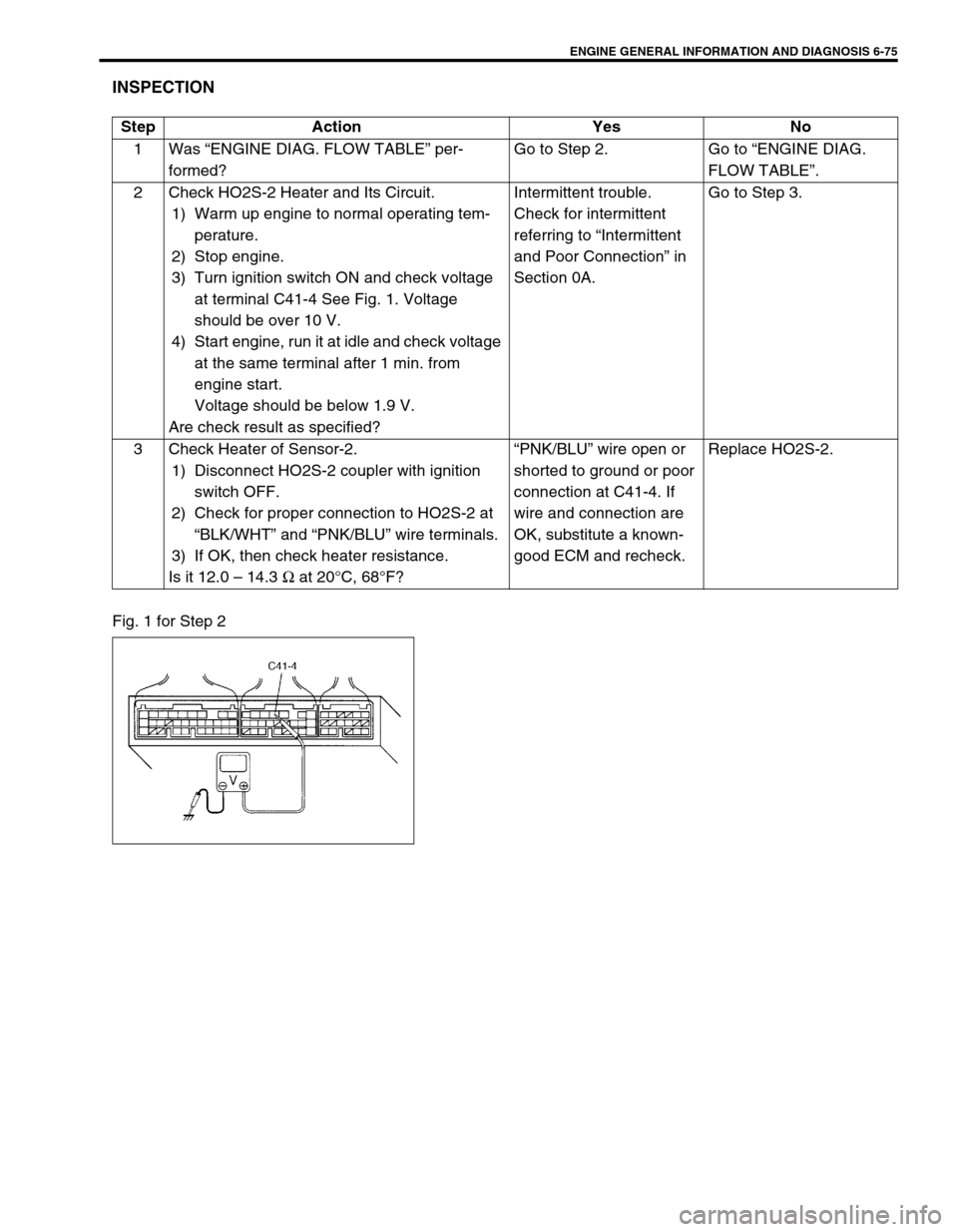
Fig. 1 for Step 2Step Action Yes No
1Was “ENGINE DIAG. FLOW TABLE” per-
formed?Go to Step 2. Go to “ENGINE DIAG.
FLOW TABLE”.
2 Check HO2S-2 Heater and Its Circuit.
1) Warm up engine to normal operating tem-
perature.
2) Stop engine.
3) Turn ignition switch ON and check voltage
at terminal C41-4 See Fig. 1. Voltage
should be over 10 V.
4) Start engine, run it at idle and check voltage
at the same terminal after 1 min. from
engine start.
Voltage should be below 1.9 V.
Are check result as specified?Intermittent trouble.
Check for intermittent
referring to “Intermittent
and Poor Connection” in
Section 0A.Go to Step 3.
3 Check Heater of Sensor-2.
1) Disconnect HO2S-2 coupler with ignition
switch OFF.
2) Check for proper connection to HO2S-2 at
“BLK/WHT” and “PNK/BLU” wire terminals.
3) If OK, then check heater resistance.
Is it 12.0 – 14.3 Ω at 20°C, 68°F?“PNK/BLU” wire open or
shorted to ground or poor
connection at C41-4. If
wire and connection are
OK, substitute a known-
good ECM and recheck.Replace HO2S-2.
Page 496 of 698
ENGINE GENERAL INFORMATION AND DIAGNOSIS 6-127
Fig. 1 for Step 2
Fig. 2 for Step 3
Table 1 for Step 2 and 3
[A] : When using SUZUKI scan tool:
[ A]
[A] : When not using SUZUKI scan tool:
[a] : Case of TYPE A is shown (See NOTE)
[b] : Case of TYPE B is shown (See NOTE)
Scan tool or voltmeter
SUZUKI
SCAN TOOLVOLTAGE
AT C42-17VOLTAGE
AT G02-13
Ignition switch ON, Small
light, heater blower fan and
rear defogger all turnedOFF OFF 0V 10 – 14V
ON ON 10 – 14V 0V
Page 546 of 698
ENGINE MECHANICAL (M13 ENGINE) 6A1-45
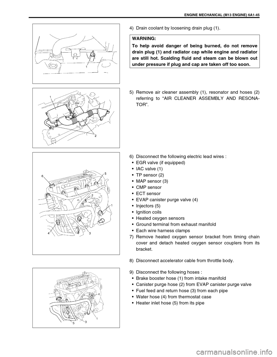
4) Drain coolant by loosening drain plug (1).
5) Remove air cleaner assembly (1), resonator and hoses (2)
referring to “AIR CLEANER ASSEMBLY AND RESONA-
TOR”.
6) Disconnect the following electric lead wires :
EGR valve (if equipped)
IAC valve (1)
TP sensor (2)
MAP sensor (3)
CMP sensor
ECT sensor
EVAP canister purge valve (4)
Injectors (5)
Ignition coils
Heated oxygen sensors
Ground terminal from exhaust manifold
Each wire harness clamps
7) Remove heated oxygen sensor bracket from timing chain
cover and detach heated oxygen sensor couplers from its
bracket.
8) Disconnect accelerator cable from throttle body.
9) Disconnect the following hoses :
Brake booster hose (1) from intake manifold
Canister purge hose (2) from EVAP canister purge valve
Fuel feed and return hose (3) from each pipe
Water hose (4) from thermostat case
Heater inlet hose (5) from its pipe WARNING:
To help avoid danger of being burned, do not remove
drain plug (1) and radiator cap while engine and radiator
are still hot. Scalding fluid and steam can be blown out
under pressure if plug and cap are taken off too soon.
Page 570 of 698
ENGINE MECHANICAL (M13 ENGINE) 6A1-69
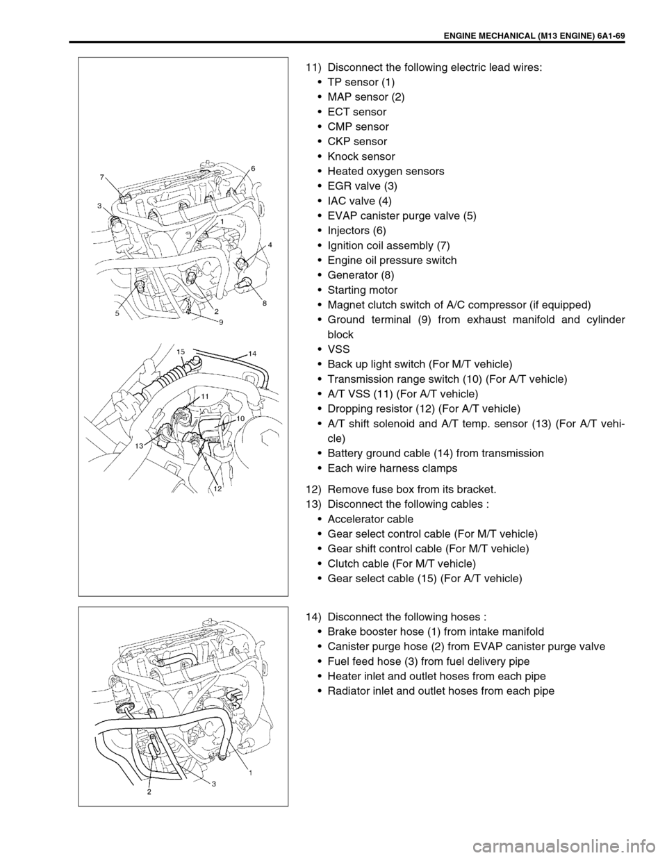
11) Disconnect the following electric lead wires:
TP sensor (1)
MAP sensor (2)
ECT sensor
CMP sensor
CKP sensor
Knock sensor
Heated oxygen sensors
EGR valve (3)
IAC valve (4)
EVAP canister purge valve (5)
Injectors (6)
Ignition coil assembly (7)
Engine oil pressure switch
Generator (8)
Starting motor
Magnet clutch switch of A/C compressor (if equipped)
Ground terminal (9) from exhaust manifold and cylinder
block
VSS
Back up light switch (For M/T vehicle)
Transmission range switch (10) (For A/T vehicle)
A/T VSS (11) (For A/T vehicle)
Dropping resistor (12) (For A/T vehicle)
A/T shift solenoid and A/T temp. sensor (13) (For A/T vehi-
cle)
Battery ground cable (14) from transmission
Each wire harness clamps
12) Remove fuse box from its bracket.
13) Disconnect the following cables :
Accelerator cable
Gear select control cable (For M/T vehicle)
Gear shift control cable (For M/T vehicle)
Clutch cable (For M/T vehicle)
Gear select cable (15) (For A/T vehicle)
14) Disconnect the following hoses :
Brake booster hose (1) from intake manifold
Canister purge hose (2) from EVAP canister purge valve
Fuel feed hose (3) from fuel delivery pipe
Heater inlet and outlet hoses from each pipe
Radiator inlet and outlet hoses from each pipe
Page 591 of 698
6B-2 ENGINE COOLING
GENERAL DESCRIPTION
The cooling system consists of the radiator cap, radiator, coolant reservoir tank, hoses, water pump, cooling fan
and thermostat. The radiator is of tube-and-fin type.
COOLING SYSTEM CIRCULATION
While the engine is warmed up (thermostat closed), coolant circulates as follows.
When coolant is warmed up to normal temperature and the thermostat opens, coolant passes through the radi-
ator core to be cooled as well as the above flow circuit.
1. Radiator inlet hose 5. Water pump 9. Heater outlet hose
2. Radiator outlet hose 6. Throttle body (Fast idle control plunger) 10. Radiator
3. Water inlet pipe 7. Engine
4. Thermostat 8. Heater inlet hose
Water pump Cylinder block
Thermostat closedCylinder head Water intake pipeThrottle body
Heater unit
Page 592 of 698
ENGINE COOLING 6B-3
COOLANT
The coolant recovery system is standard. The coolant in the radiator expands with heat, and the overflow is col-
lected in the reservoir.
When the system cools down, the coolant is drawn back into the radiator.
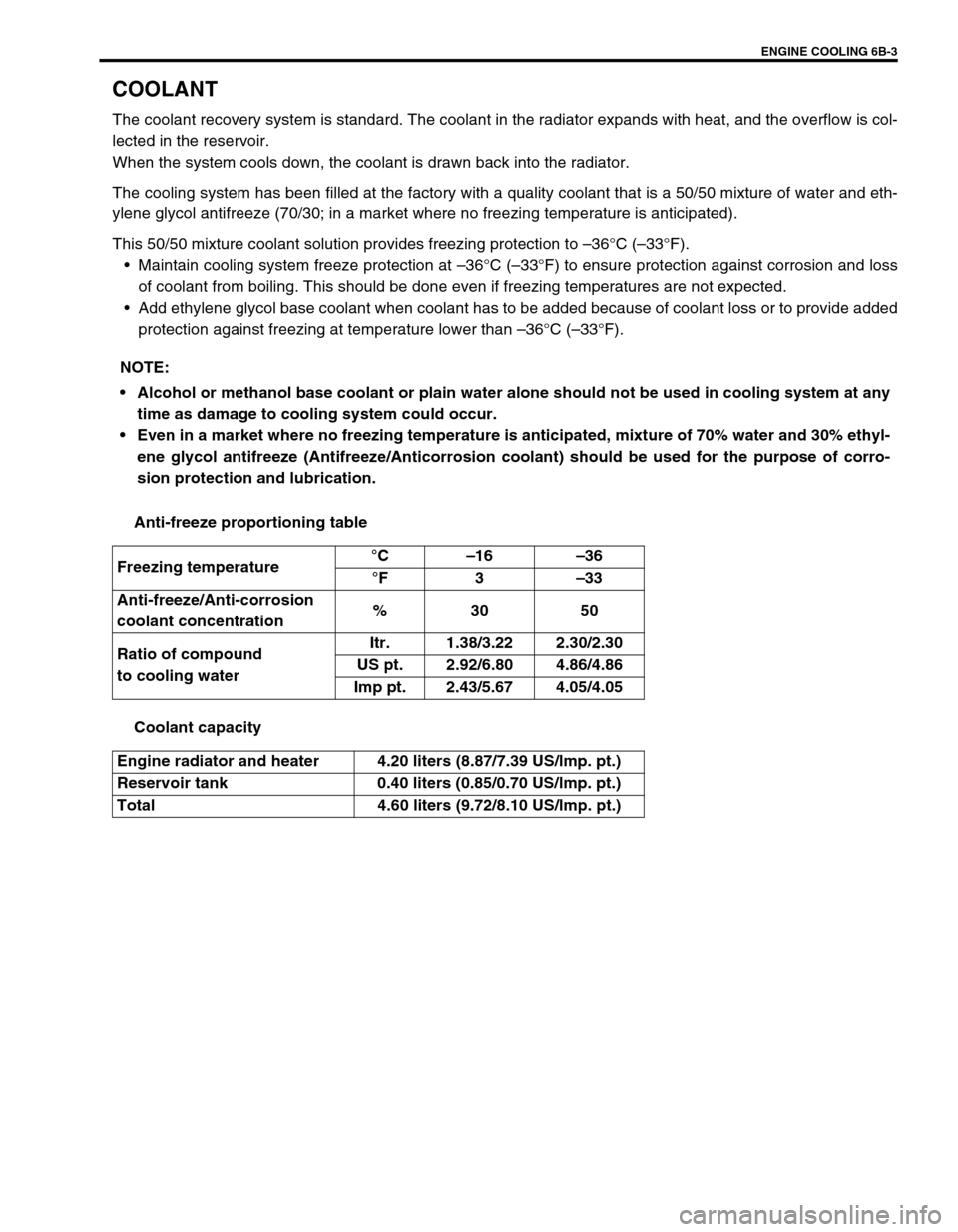
The cooling system has been filled at the factory with a quality coolant that is a 50/50 mixture of water and eth-
ylene glycol antifreeze (70/30; in a market where no freezing temperature is anticipated).
This 50/50 mixture coolant solution provides freezing protection to –36°C (–33°F).
Maintain cooling system freeze protection at –36°C (–33°F) to ensure protection against corrosion and loss
of coolant from boiling. This should be done even if freezing temperatures are not expected.
Add ethylene glycol base coolant when coolant has to be added because of coolant loss or to provide added
protection against freezing at temperature lower than –36°C (–33°F).
Anti-freeze proportioning table
Coolant capacity NOTE:
Alcohol or methanol base coolant or plain water alone should not be used in cooling system at any
time as damage to cooling system could occur.
Even in a market where no freezing temperature is anticipated, mixture of 70% water and 30% ethyl-
ene glycol antifreeze (Antifreeze/Anticorrosion coolant) should be used for the purpose of corro-
sion protection and lubrication.
Freezing temperature°C–16–36
°F3–33
Anti-freeze/Anti-corrosion
coolant concentration%30 50
Ratio of compound
to cooling waterItr. 1.38/3.22 2.30/2.30
US pt. 2.92/6.80 4.86/4.86
Imp pt. 2.43/5.67 4.05/4.05
Engine radiator and heater 4.20 liters (8.87/7.39 US/lmp. pt.)
Reservoir tank 0.40 liters (0.85/0.70 US/lmp. pt.)
Total 4.60 liters (9.72/8.10 US/lmp. pt.)