2000 SUZUKI SWIFT radiator
[x] Cancel search: radiatorPage 404 of 698

ENGINE GENERAL INFORMATION AND DIAGNOSIS 6-35
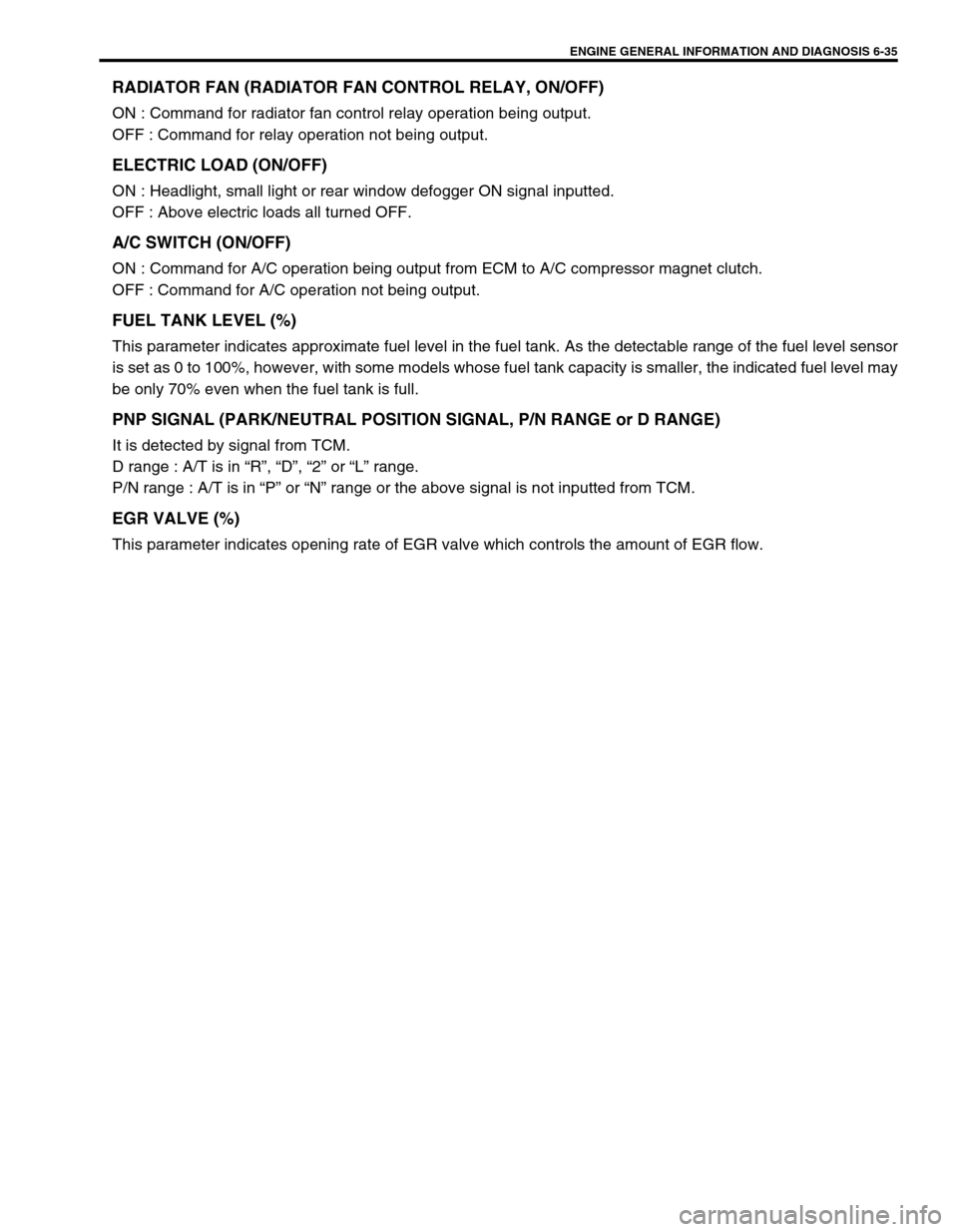
RADIATOR FAN (RADIATOR FAN CONTROL RELAY, ON/OFF)
ON : Command for radiator fan control relay operation being output.
OFF : Command for relay operation not being output.
ELECTRIC LOAD (ON/OFF)
ON : Headlight, small light or rear window defogger ON signal inputted.
OFF : Above electric loads all turned OFF.
A/C SWITCH (ON/OFF)
ON : Command for A/C operation being output from ECM to A/C compressor magnet clutch.
OFF : Command for A/C operation not being output.
FUEL TANK LEVEL (%)
This parameter indicates approximate fuel level in the fuel tank. As the detectable range of the fuel level sensor
is set as 0 to 100%, however, with some models whose fuel tank capacity is smaller, the indicated fuel level may
be only 70% even when the fuel tank is full.
PNP SIGNAL (PARK/NEUTRAL POSITION SIGNAL, P/N RANGE or D RANGE)
It is detected by signal from TCM.
D range : A/T is in “R”, “D”, “2” or “L” range.
P/N range : A/T is in “P” or “N” range or the above signal is not inputted from TCM.
EGR VALVE (%)
This parameter indicates opening rate of EGR valve which controls the amount of EGR flow.
Page 407 of 698

6-38 ENGINE GENERAL INFORMATION AND DIAGNOSIS
TERMINAL
NO.CIRCUIT NORMAL
VOLTAGECONDITION
C411 A/C compressor clutch 0 V Ignition switch ON
2 EGR valve (stepper motor coil 1)
(if equipped)10 – 14 V Ignition switch ON
3 Throttle position sensor 0.2 – 1.0 V Ignition switch ON
Throttle valve at idle position
2.8 – 4.8 V Ignition switch ON
Throttle valve at full open position
4 Heater of HO2S-2
(Vehicle with immobilizer indicator lamp)10 – 14 V Ignition switch ON
5 Power source 10 – 14 V Ignition switch ON
6 Power source 10 – 14 V Ignition switch ON
7 Engine start switch
(Engine start signal)6 – 12 V While engine cranking
0 V Other than above
8 EGR valve (stepper motor coil 3)
(if equipped)10 – 14 V Ignition switch ON
9 EGR valve (stepper motor coil 2)
(if equipped)10 – 14 V Ignition switch ON
10 Main relay 10 – 14 V Ignition switch OFF
0.4 – 1.5 V Ignition switch ON
11 Blank––
12 Blank––
13 Heated oxygen sensor-2
(Vehicle with immobilizer indicator lamp)Refer to DTC P0130 diag. flow table
14 D-range ID-up signal (A/T) 10 – 14 V Ignition switch ON
15 R-range signal (A/T) 0 V Ignition switch ON
16 A/C (input) signal 10 – 14 V Ignition switch ON
A/C switch OFF
0 – 2 V Ignition switch ON
A/C switch ON
17 EGR valve (stepper motor coil 4)
(if equipped)10 – 14 V Ignition switch ON
18 Radiator fan control relay 10 – 14 V Ignition switch ON
Engine coolant temp. : 9.5°C or
lower (203°F)
0 – 1 V Ignition switch ON
Engine coolant temp. : 97.5°C
(208°F) or higher
19 Fuel pump relay 0 – 1 V For 2 seconds after ignition switch
ON
10 – 14 V After the above time
20–––
Page 408 of 698

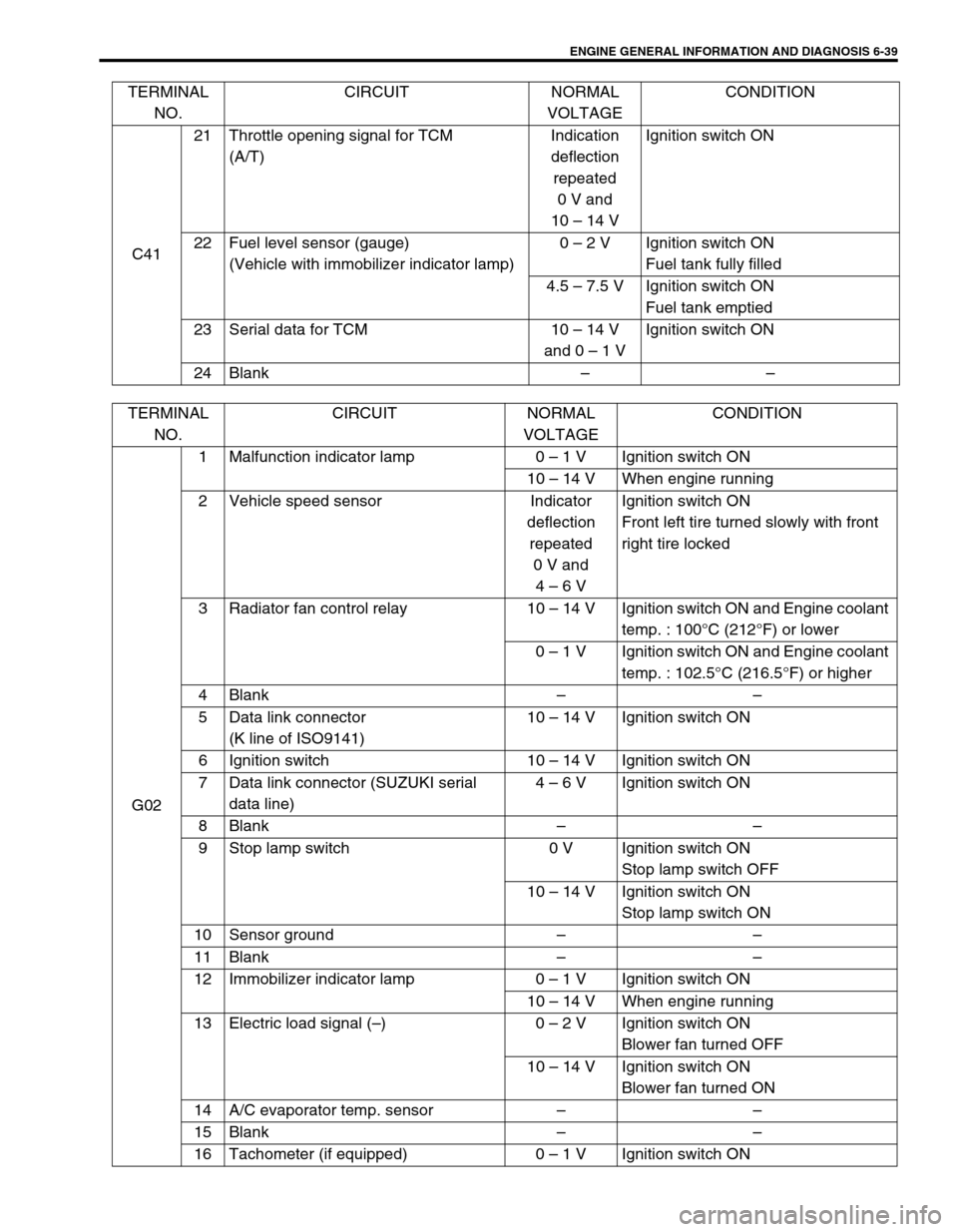
ENGINE GENERAL INFORMATION AND DIAGNOSIS 6-39
C4121 Throttle opening signal for TCM
(A/T)Indication
deflection
repeated
0 V and
10 – 14 VIgnition switch ON
22 Fuel level sensor (gauge)
(Vehicle with immobilizer indicator lamp)0 – 2 V Ignition switch ON
Fuel tank fully filled
4.5 – 7.5 V Ignition switch ON
Fuel tank emptied
23 Serial data for TCM 10 – 14 V
and 0 – 1 VIgnition switch ON
24 Blank–– TERMINAL
NO.CIRCUIT NORMAL
VOLTAGECONDITION
TERMINAL
NO.CIRCUIT NORMAL
VOLTAGECONDITION
G021 Malfunction indicator lamp 0 – 1 V Ignition switch ON
10 – 14 V When engine running
2 Vehicle speed sensor Indicator
deflection
repeated
0 V and
4 – 6 VIgnition switch ON
Front left tire turned slowly with front
right tire locked
3 Radiator fan control relay 10 – 14 V Ignition switch ON and Engine coolant
temp. : 100°C (212°F) or lower
0 – 1 V Ignition switch ON and Engine coolant
temp. : 102.5°C (216.5°F) or higher
4 Blank––
5 Data link connector
(K line of ISO9141)10 – 14 V Ignition switch ON
6 Ignition switch 10 – 14 V Ignition switch ON
7 Data link connector (SUZUKI serial
data line)4 – 6 V Ignition switch ON
8 Blank––
9 Stop lamp switch 0 V Ignition switch ON
Stop lamp switch OFF
10 – 14 V Ignition switch ON
Stop lamp switch ON
10 Sensor ground––
11 Blank––
12 Immobilizer indicator lamp 0 – 1 V Ignition switch ON
10 – 14 V When engine running
13 Electric load signal (–)0 – 2 V Ignition switch ON
Blower fan turned OFF
10 – 14 V Ignition switch ON
Blower fan turned ON
14 A/C evaporator temp. sensor––
15 Blank––
16 Tachometer (if equipped) 0 – 1 V Ignition switch ON
Page 410 of 698

ENGINE GENERAL INFORMATION AND DIAGNOSIS 6-41
TERMINAL
NO.CIRCUIT NORMAL
VOLTAGECONDITION
C411 A/C compressor clutch 0 V Ignition switch ON
2–––
3–––
4–––
5 Power source 10 – 14 V Ignition switch ON
6 Power source 10 – 14 V Ignition switch ON
7 Power source for back-up 10 – 14V Anytime
8 Monitor output (Vehicle without immobi-
lizer indicator lamp)––
9 Radiator fan control relay 10 – 14 V Ignition switch ON and Engine
coolant temp. : 100°C (212°F)or
lower
0 – 1 V Ignition switch ON and Engine
coolant temp. : 102.5°C (216.5°F)
or higher
10 Main relay 10 – 14 V Ignition switch OFF
0.4 – 1.5 V Ignition switch ON
11 Ignition switch 10 – 14 V Ignition switch ON
12 Blank––
13–––
14 Diag. Switch terminal (Vehicle without
immobilizer indicator lamp)4 – 6 V Ignition switch ON
15 Test switch terminal (Vehicle without
immobilizer indicator lamp)4 – 6 V Ignition switch ON
16 A/C (input) signal 10 – 14 V Ignition switch ON
A/C switch OFF
0 – 2 V Ignition switch ON
A/C switch ON
17 Electric load signal (+) 0 V Ignition switch ON
Small light and rear defogger OFF
10 – 14 V Ignition switch ON
Small light and rear defogger OFF
18 Radiator fan control relay 10 – 14 V Ignition switch ON
Engine coolant temp. : 9.5°C or
lower (203°F)
0 – 1 V Ignition switch ON
Engine coolant temp. : 97.5°C
(208°F) or higher
19 Fuel pump relay 0 – 1 V For 2 seconds after ignition switch
ON
10 – 14 V After the above time
20 Engine start switch
(Engine start signal)6 – 12 V While engine cranking
0 V Other than above
Page 412 of 698

ENGINE GENERAL INFORMATION AND DIAGNOSIS 6-43
Resistance Check
1) Disconnect ECM couplers from ECM with ignition switch
OFF.
2) Check resistance between each terminal of connectors dis-
connected.
TERMINAL RESISTANCE TABLE
For TYPE A (Refer to NOTE in “ECM VOLTAGE VALUES TABLE” for applicable model) CAUTION:
Never touch terminals of ECM itself or connect voltmeter
or ohmmeter.
CAUTION:
Be sure to connect ohmmeter probe from wire harness
side of coupler.
Be sure to turn OFF ignition switch for this check.
Resistance in table below represents that when parts
temperature is 20°C (68°F).
1. ECM coupler disconnected
2. Ohmmeter
TERMINALS CIRCUIT STANDARD
RESISTANCE
C42-7 to G02-6 HO2S-1 heater (if equipped) 5.0 – 6.4 Ω
C41-4 to G02-6 HO2S-2 heater (if equipped) 12.0 – 14.3 Ω
C42-9 to C41-5/6 No.1 injector 11.3 – 13.8 Ω
C42-21 to C41-5/6 No.2 injector 11.3 – 13.8 Ω
C42-31 to C41-5/6 No.3 injector 11.3 – 13.8 Ω
C42-8 to C41-5/6 No.4 injector 11.3 – 13.8 Ω
C41-2 to C41-5/6 EGR valve (stepper motor coil 1) (if equipped) 20 – 24 Ω
C41-9 to C41-5/6 EGR valve (stepper motor coil 2) (if equipped) 20 – 24 Ω
C41-8 to C41-5/6 EGR valve (stepper motor coil 3) (if equipped) 20 – 24 Ω
C41-17 to C41-5/6 EGR valve (stepper motor coil 4) (if equipped) 20 – 24 Ω
C42-4 to C41-5/6 EVAP canister purge valve 30 – 34 Ω
C41-19 to G02-6 Fuel pump relay 56 – 146 Ω
C41-1 to Body ground A/C compressor clutch 3 – 5.5 Ω
C41-18 to C41-5/6 Radiator fan control relay No.1 56 – 146 Ω
C41-10 to G02-17 Main relay 56 – 146 Ω
C42-1 to Body ground Ground Continuity
C42-2 to Body ground Ground Continuity
C42-3 to Body ground Ground Continuity
Page 413 of 698

6-44 ENGINE GENERAL INFORMATION AND DIAGNOSIS
For TYPE B (Refer to NOTE in “ECM VOLTAGE VALUES TABLE” for applicable model.)
TERMINALS CIRCUIT STANDARD
RESISTANCE
C42-7 to C41-11 HO2S-1 heater (if equipped) 5.0 – 6.4 Ω
C41-4 to C41-11 HO2S-2 heater (if equipped) 12.0 – 14.3 Ω
C42-9 to C41-5/6 No.1 injector 11.3 – 13.8 Ω
C42-21 to C41-5/6 No.2 injector 11.3 – 13.8 Ω
C42-31 to C41-5/6 No.3 injector 11.3 – 13.8 Ω
C42-8 to C41-5/6 No.4 injector 11.3 – 13.8 Ω
C42-18 to C41-5/6 EGR valve (stepper motor coil 1) (if equipped) 20 – 24 Ω
C42-29 to C41-5/6 EGR valve (stepper motor coil 2) (if equipped) 20 – 24 Ω
C42-17 to C41-5/6 EGR valve (stepper motor coil 3) (if equipped) 20 – 24 Ω
C42-28 to C41-5/6 EGR valve (stepper motor coil 4) (if equipped) 20 – 24 Ω
C42-4 to C41-5/6 EVAP canister purge valve 30 – 34 Ω
C41-19 to G02-6 Fuel pump relay 56 – 146 Ω
C41-1 to Body ground A/C compressor clutch 3 – 5.5 Ω
C41-18 to C41-5/6 Radiator fan control relay No.1 56 – 146 Ω
C41-10 to C41-7 Main relay 56 – 146 Ω
C42-1 to Body ground Ground Continuity
C42-2 to Body ground Ground Continuity
C42-3 to Body ground Ground Continuity
Page 414 of 698

ENGINE GENERAL INFORMATION AND DIAGNOSIS 6-45
COMPONENT LOCATION
1. TP sensor 9. Radiator fan control relay No.3 17. ECM
2. MAP sensor 10. EVAP canister purge valve 18. Monitor connector
3. IAC valve 11. ECT sensor 19. VSS
4. IAT sensor 12. Ignition coil with igniter 20. Knock sensor (if equipped)
5. Radiator fan control relay No.1 13. HO2S-1 (if equipped) 21. CMP sensor
6. Main relay 14. HO2S-2 (if equipped) 22. EGR valve (if equipped)
7. Fuel pump relay 15. CKP sensor✱ : This figure shows left-hand steering vehicle, these parts are
installed at the other side for right-hand steering vehicle.
8. Radiator fan control relay No.2 16. TCM
1
3
24
518
6 7
20
19
8
9 1617
21
15
131214
10
22
11
Page 470 of 698

ENGINE GENERAL INFORMATION AND DIAGNOSIS 6-101
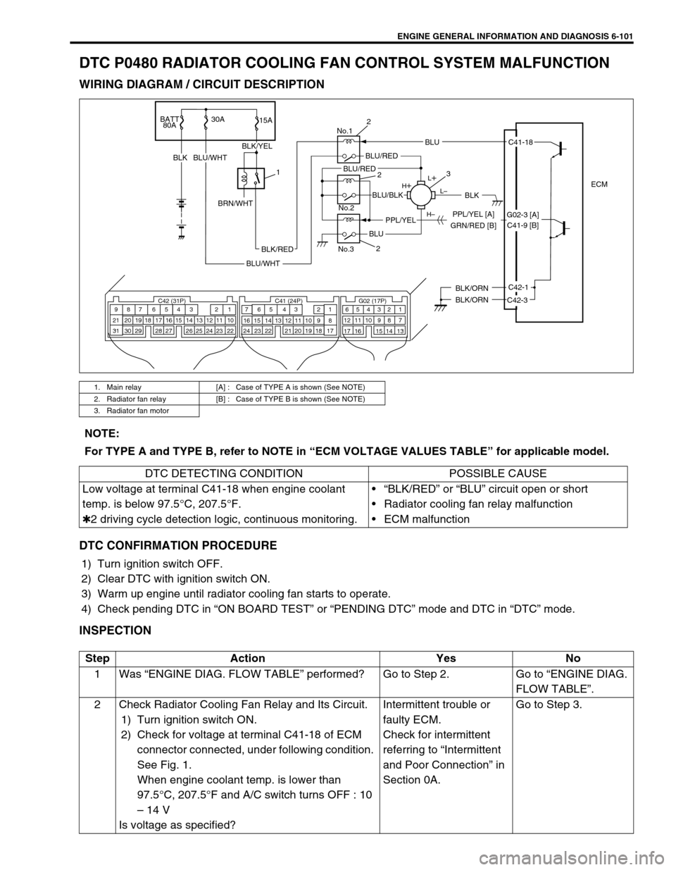
DTC P0480 RADIATOR COOLING FAN CONTROL SYSTEM MALFUNCTION
WIRING DIAGRAM / CIRCUIT DESCRIPTION
DTC CONFIRMATION PROCEDURE
1) Turn ignition switch OFF.
2) Clear DTC with ignition switch ON.
3) Warm up engine until radiator cooling fan starts to operate.
4) Check pending DTC in “ON BOARD TEST” or “PENDING DTC” mode and DTC in “DTC” mode.
INSPECTION
1. Main relay [A] : Case of TYPE A is shown (See NOTE)
2. Radiator fan relay [B] : Case of TYPE B is shown (See NOTE)
3. Radiator fan motor
BATT
80A30A
15A
BLKBLU/WHT
ECM
BLK/ORN
BLK/ORNC42-1
C42-3
L
L–
H– H
No.1
No.2
No.3
BLU
C42 (31P) C41 (24P) G02 (17P)1 2 3 4 5 6 7 8 9
10 11 12 13 14 15 16 17 18 19 20 21
22 23 24 25 26 28 27 29 30 315 6
1 2 3 4 5 6 7
11 12
9 10 11 13 12 14 15 16
16 171 2
7 8
13 14 3 4
9 10
15 17 188
19 20 21 22 23 24
C41-18
GRN/RED [B]PPL/YEL [A]
BLK/RED
BLU/WHT
BLU/RED
BLK
BLU
BLU/BLK
PPL/YEL
BLU/RED
BLK/YEL
1
BRN/WHT
2
3
2
2
G02-3 [A]
C41-9 [B]
NOTE:
For TYPE A and TYPE B, refer to NOTE in “ECM VOLTAGE VALUES TABLE” for applicable model.
DTC DETECTING CONDITION POSSIBLE CAUSE
Low voltage at terminal C41-18 when engine coolant
temp. is below 97.5°C, 207.5°F.
✱2 driving cycle detection logic, continuous monitoring.“BLK/RED” or “BLU” circuit open or short
Radiator cooling fan relay malfunction
ECM malfunction
Step Action Yes No
1Was “ENGINE DIAG. FLOW TABLE” performed? Go to Step 2. Go to “ENGINE DIAG.
FLOW TABLE”.
2 Check Radiator Cooling Fan Relay and Its Circuit.
1) Turn ignition switch ON.
2) Check for voltage at terminal C41-18 of ECM
connector connected, under following condition.
See Fig. 1.
When engine coolant temp. is lower than
97.5°C, 207.5°F and A/C switch turns OFF : 10
– 14 V
Is voltage as specified?Intermittent trouble or
faulty ECM.
Check for intermittent
referring to “Intermittent
and Poor Connection” in
Section 0A.Go to Step 3.