Page 471 of 698
6-102 ENGINE GENERAL INFORMATION AND DIAGNOSIS
Fig. 1 for Step 2
Fig. 2 for Step 3
Fig. 3 for Step 33 Check Radiator Cooling Fan Control Relay.
1) Turn ignition switch OFF and remove radiator
cooling fan relay.
2) Check for proper connection to the relay at
“BLK/RED”, “BLU”, “BLU/RED” and “BLU/BLK”
wire terminals.
3) If OK, then measure resistance between termi-
nals a and b. See Fig. 2 and 3.
Is it 56 – 146 Ω?“BLK/RED” or “BLU” cir-
cuit open or short.
If wires and connections
are OK, substitute a
known-good ECM and
recheck.Replace radiator cool-
ing fan relay. Step Action Yes No
1. Radiator fan relay No.11
Page 497 of 698
![SUZUKI SWIFT 2000 1.G RG413 Service Workshop Manual 6-128 ENGINE GENERAL INFORMATION AND DIAGNOSIS
TABLE B-7 RADIATOR FAN CONTROL SYSTEM CHECK
INSPECTION
1. Radiator fan relay No.1 3. Radiator fan relay No.3 [A] : Case of TYPE A is shown (See NOTE)
2. SUZUKI SWIFT 2000 1.G RG413 Service Workshop Manual 6-128 ENGINE GENERAL INFORMATION AND DIAGNOSIS
TABLE B-7 RADIATOR FAN CONTROL SYSTEM CHECK
INSPECTION
1. Radiator fan relay No.1 3. Radiator fan relay No.3 [A] : Case of TYPE A is shown (See NOTE)
2.](/manual-img/20/7606/w960_7606-496.png)
6-128 ENGINE GENERAL INFORMATION AND DIAGNOSIS
TABLE B-7 RADIATOR FAN CONTROL SYSTEM CHECK
INSPECTION
1. Radiator fan relay No.1 3. Radiator fan relay No.3 [A] : Case of TYPE A is shown (See NOTE)
2. Radiator fan relay No.2 4. Radiator fan [B] : Case of TYPE B is shown (See NOTE)
BATT
80A30A
15A
BLKBLU/WHT
ECM
BLK/ORN
BLK/ORNC42-1
C42-3
L+
L–
H– H+
BLU
C42 (31P) C41 (24P) G02 (17P)1 2 3 4 5 6 7 8 9
10 11 12 13 14 15 16 17 18 19 20 21
22 23 24 25 26 28 27 29 30 315 6
1 2 3 4 5 6 7
11 12
9 10 11 13 12 14 15 16
16 171 2
7 8
13 14 3 4
9 10
15 17 188
19 20 21 22 23 24
C41-18
GRN/RED [B]PPL/YEL [A]
BLK/RED
BLU/WHT
BLU/RED
BLK
BLU
BLU/BLK
PPL/YEL
BLU/REDBLK/YEL
BRN/WHT
1
2
34
G02-3 [A]
C41-9 [B]
NOTE:
For TYPE A and TYPE B, refer to NOTE in “ECM VOLTAGE VALUES TABLE” for applicable model.
Step Action Yes No
1 Check Fan Control System.
1) Connect scan tool to DLC with ignition switch OFF.
2) Start engine and select “DATA LIST” mode on scan
tool.
3) Warm up engine until coolant temp. is 97.5°C, 208°F or
higher and A/C switch turn OFF. (If engine coolant
temp. does not rise, check engine cooling system or
ECT sensor.) See Fig. 1.
Is radiator cooling fan started when engine coolant temp.
reached above temp.?Radiator cooling fan
control system is in
good condition.Go to Step 2.
2 Check Radiator Fan Relay and Its Circuit.
1) Check DTC and pending DTC with scan tool.
Is DTC P0480 displayed?Go to DTC P0480 Diag.
Flow Table.Go to Step 3.
3 Check Radiator Fan Relays.
1) Turn ignition switch OFF and remove radiator cooling
fan relays. (No.1 – No.3)
2) Check for proper connection to relay at terminals “c”
and “d”.
3) If OK, check that there is continuity between “c” and “d”
when battery is connected to terminals “a” and “b”. See
Fig. 2.
Is check result satisfactory?Go to Step 4. Replace radia-
tor fan relay(s).
Page 498 of 698
ENGINE GENERAL INFORMATION AND DIAGNOSIS 6-129
Fig. 1 for Step 1
Fig. 2 for Step 34 Check Radiator Fan.
1) Turn ignition switch OFF.
2) Disconnect cooling fan motor connector.
3) Check for proper connection to motor at “BLU/RED”
and “BLK” terminals.
4) If OK, connect battery to motor and check for operation.
See Fig. 3.
Is it in good condition?“BLU/WHT”, “BLU/
RED” or “BLK” circuit
open.Replace radia-
tor fan motor. Step Action Yes No
[A] : When using SUZUKI scan tool:[ A]
1. Radiator fan No.1
2. Radiator fan No.2
3. Radiator fan No.3
1
1
2
3
2, 3ca
db
Page 517 of 698
6A1-16 ENGINE MECHANICAL (M13 ENGINE)
THROTTLE BODY AND INTAKE MANIFOLD
REMOVAL
1) Relieve fuel pressure according to fuel pressure relief proce-
dure described in Section 6.
2) Disconnect negative cable at battery.
3) Drain coolant by loosening drain plug (1).
1. Intake manifold 7. EVAP canister purge valve 13. Intake manifold mounting bolt (short) 19. Cushion
2. Intake manifold gasket 8. TP sensor 14. Intake manifold mounting bolt (long) 20. Fuel delivery pipe mounting bolt
3. Throttle body 9. IAC valve 15. EGR pipe gasket Tightening torque
4. Gasket 10. Fuel delivery pipe 16. O-Ring Do not reuse.
5. EGR pipe 11. Intake manifold stiffener 17. Grommet
6. MAP sensor 12. Intake manifold mounting nut 18. Injector assembly
WARNING:
To help avoid danger of being burned, do not remove
drain plug (1) and radiator cap while engine and radiator
are still hot. Scalding fluid and steam can be blown out
under pressure if plug and cap are taken off too soon.
Page 546 of 698

ENGINE MECHANICAL (M13 ENGINE) 6A1-45
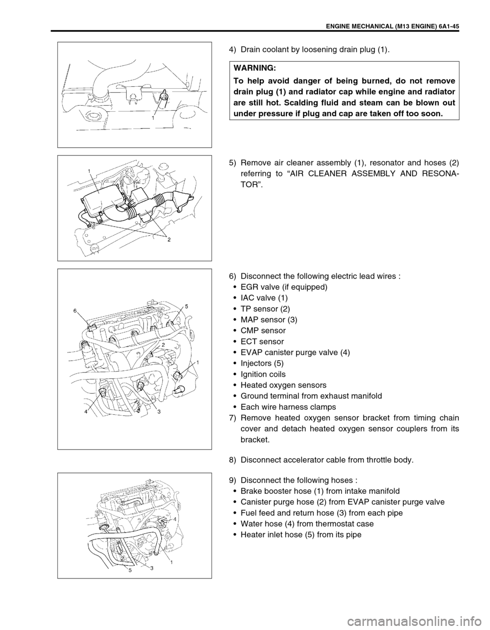
4) Drain coolant by loosening drain plug (1).
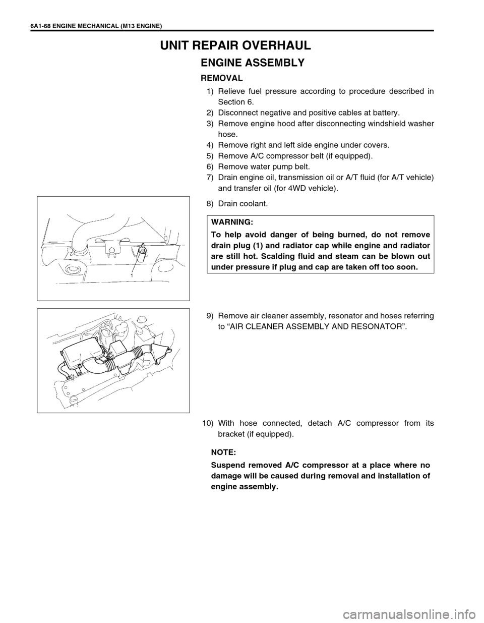
5) Remove air cleaner assembly (1), resonator and hoses (2)
referring to “AIR CLEANER ASSEMBLY AND RESONA-
TOR”.
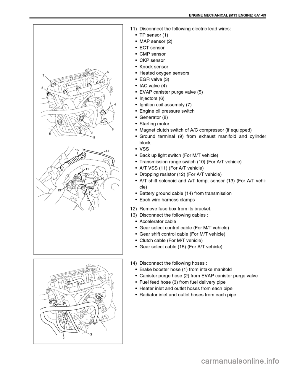
6) Disconnect the following electric lead wires :
EGR valve (if equipped)
IAC valve (1)
TP sensor (2)
MAP sensor (3)
CMP sensor
ECT sensor
EVAP canister purge valve (4)
Injectors (5)
Ignition coils
Heated oxygen sensors
Ground terminal from exhaust manifold
Each wire harness clamps
7) Remove heated oxygen sensor bracket from timing chain
cover and detach heated oxygen sensor couplers from its
bracket.
8) Disconnect accelerator cable from throttle body.
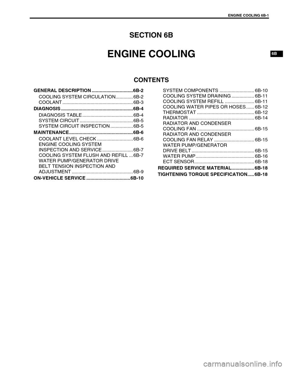
9) Disconnect the following hoses :
Brake booster hose (1) from intake manifold
Canister purge hose (2) from EVAP canister purge valve
Fuel feed and return hose (3) from each pipe
Water hose (4) from thermostat case
Heater inlet hose (5) from its pipe WARNING:
To help avoid danger of being burned, do not remove
drain plug (1) and radiator cap while engine and radiator
are still hot. Scalding fluid and steam can be blown out
under pressure if plug and cap are taken off too soon.
Page 569 of 698

6A1-68 ENGINE MECHANICAL (M13 ENGINE)
UNIT REPAIR OVERHAUL
ENGINE ASSEMBLY
REMOVAL
1) Relieve fuel pressure according to procedure described in
Section 6.
2) Disconnect negative and positive cables at battery.
3) Remove engine hood after disconnecting windshield washer
hose.
4) Remove right and left side engine under covers.
5) Remove A/C compressor belt (if equipped).
6) Remove water pump belt.
7) Drain engine oil, transmission oil or A/T fluid (for A/T vehicle)
and transfer oil (for 4WD vehicle).
8) Drain coolant.
9) Remove air cleaner assembly, resonator and hoses referring
to “AIR CLEANER ASSEMBLY AND RESONATOR”.
10) With hose connected, detach A/C compressor from its
bracket (if equipped). WARNING:
To help avoid danger of being burned, do not remove
drain plug (1) and radiator cap while engine and radiator
are still hot. Scalding fluid and steam can be blown out
under pressure if plug and cap are taken off too soon.
NOTE:
Suspend removed A/C compressor at a place where no
damage will be caused during removal and installation of
engine assembly.
Page 570 of 698

ENGINE MECHANICAL (M13 ENGINE) 6A1-69
11) Disconnect the following electric lead wires:
TP sensor (1)
MAP sensor (2)
ECT sensor
CMP sensor
CKP sensor
Knock sensor
Heated oxygen sensors
EGR valve (3)
IAC valve (4)
EVAP canister purge valve (5)
Injectors (6)
Ignition coil assembly (7)
Engine oil pressure switch
Generator (8)
Starting motor
Magnet clutch switch of A/C compressor (if equipped)
Ground terminal (9) from exhaust manifold and cylinder
block
VSS
Back up light switch (For M/T vehicle)
Transmission range switch (10) (For A/T vehicle)
A/T VSS (11) (For A/T vehicle)
Dropping resistor (12) (For A/T vehicle)
A/T shift solenoid and A/T temp. sensor (13) (For A/T vehi-
cle)
Battery ground cable (14) from transmission
Each wire harness clamps
12) Remove fuse box from its bracket.
13) Disconnect the following cables :
Accelerator cable
Gear select control cable (For M/T vehicle)
Gear shift control cable (For M/T vehicle)
Clutch cable (For M/T vehicle)
Gear select cable (15) (For A/T vehicle)
14) Disconnect the following hoses :
Brake booster hose (1) from intake manifold
Canister purge hose (2) from EVAP canister purge valve
Fuel feed hose (3) from fuel delivery pipe
Heater inlet and outlet hoses from each pipe
Radiator inlet and outlet hoses from each pipe
Page 590 of 698

ENGINE COOLING 6B-1
6B
SECTION 6B
ENGINE COOLING
CONTENTS
GENERAL DESCRIPTION ...............................6B-2
COOLING SYSTEM CIRCULATION............. 6B-2
COOLANT ..................................................... 6B-3
DIAGNOSIS ......................................................6B-4
DIAGNOSIS TABLE ...................................... 6B-4
SYSTEM CIRCUIT ........................................ 6B-5
SYSTEM CIRCUIT INSPECTION ................. 6B-5
MAINTENANCE................................................6B-6
COOLANT LEVEL CHECK ........................... 6B-6
ENGINE COOLING SYSTEM
INSPECTION AND SERVICE ....................... 6B-7
COOLING SYSTEM FLUSH AND REFILL ... 6B-7
WATER PUMP/GENERATOR DRIVE
BELT TENSION INSPECTION AND
ADJUSTMENT .............................................. 6B-9
ON-VEHICLE SERVICE .................................6B-10SYSTEM COMPONENTS .......................... 6B-10
COOLING SYSTEM DRAINING ................. 6B-11
COOLING SYSTEM REFILL ...................... 6B-11
COOLING WATER PIPES OR HOSES ...... 6B-12
THERMOSTAT ........................................... 6B-12
RADIATOR ................................................. 6B-14
RADIATOR AND CONDENSER
COOLING FAN ........................................... 6B-15
RADIATOR AND CONDENSER
COOLING FAN RELAY .............................. 6B-15
WATER PUMP/GENERATOR
DRIVE BELT ............................................... 6B-15
WATER PUMP............................................ 6B-16
ECT SENSOR............................................. 6B-18
REQUIRED SERVICE MATERIAL................. 6B-18
TIGHTENING TORQUE SPECIFICATION..... 6B-18