Page 122 of 698

MANUAL RACK AND PINION 3B-1
6F1
6F2
6G
6H
7A
3B
7C1
7D
7E
7F
8A
8B
8C
8D
8E
9
10
10A
10B
SECTION 3B
MANUAL RACK AND PINION
CONTENTS
GENERAL DESCRIPTION .............................. 3B-2
DIAGNOSIS ..................................................... 3B-3
ON-VEHICLE SERVICE .................................. 3B-4
LUBRICATION ............................................. 3B-4
TIE ROD END .............................................. 3B-6
MANUAL RACK AND PINION ASSEMBLY
(STEERING GEAR CASE) .......................... 3B-7
RACK BOOT/TIE ROD .............................. 3B-10STEERING RACK PLUNGER ................... 3B-12
STEERING PINION ................................... 3B-14
STEERING RACK...................................... 3B-15
PINION BEARING ..................................... 3B-17
RACK BUSHING ........................................ 3B-18
REQUIRED SERVICE MATERIAL................ 3B-19
SPECIAL TOOL ............................................ 3B-20
WARNING:
For vehicles equipped with a Air Bag System
Service on or around air bag system components or wiring must be performed only by an autho-
rized suzuki dealer. Please observe all WARNINGS and CAUTIONS in SECTION 10B and Precau-
tions, Air Bag System Components and Wiring Location view in Section 10B before performing
service on or around air bag system components or wiring. Failure to follow WARNINGS could
result in unintended activation of the system or could render the system inoperative. Either of these
two conditions may result in severe injury.
Technical service work must be started at least 90 seconds after the ignition switch is turned to the
“LOCK” position and the negative cable is disconnected from the battery. Otherwise, the system
may be deployed by reserve energy in the Sensing and Diagnostic Module (SDM).
NOTE:
All steering gear fasteners are important attaching parts in that they could affect the performance of
vital parts and systems, and/or could result in major repair expense. They must be replaced with one
of the same part number or with an equivalent part if replacement becomes necessary. Do not use a
replacement part of lesser quality or substitute design. Torque values must be used as specified dur-
ing reassembly to assure proper retention of these parts.
Page 127 of 698
3B-6 MANUAL RACK AND PINION
TIE ROD END
REMOVAL
1) Hoist vehicle and remove wheel.
2) Remove split pin (1) and tie rod end castle nut (3) from steer-
ing knuckle (2).
3) Disconnect tie rod end from knuckle, using special tool.
Special tool
(A) : 09913-65210
4) For ease of adjustment after installation, make marking (2) of
tie rod end lock nut (3) position on tie rod end thread. Then
loosen lock nut and remove tie rod end (4) from tie rod (1).
INSTALLATION
1) Install tie rod end lock nut (3) and tie rod end (4) to tie rod
(1). Align lock nut with mar (2) on tie rod thread.
5. Knuckle
6. Castle nut
7. Split pin
Page 128 of 698

MANUAL RACK AND PINION 3B-7
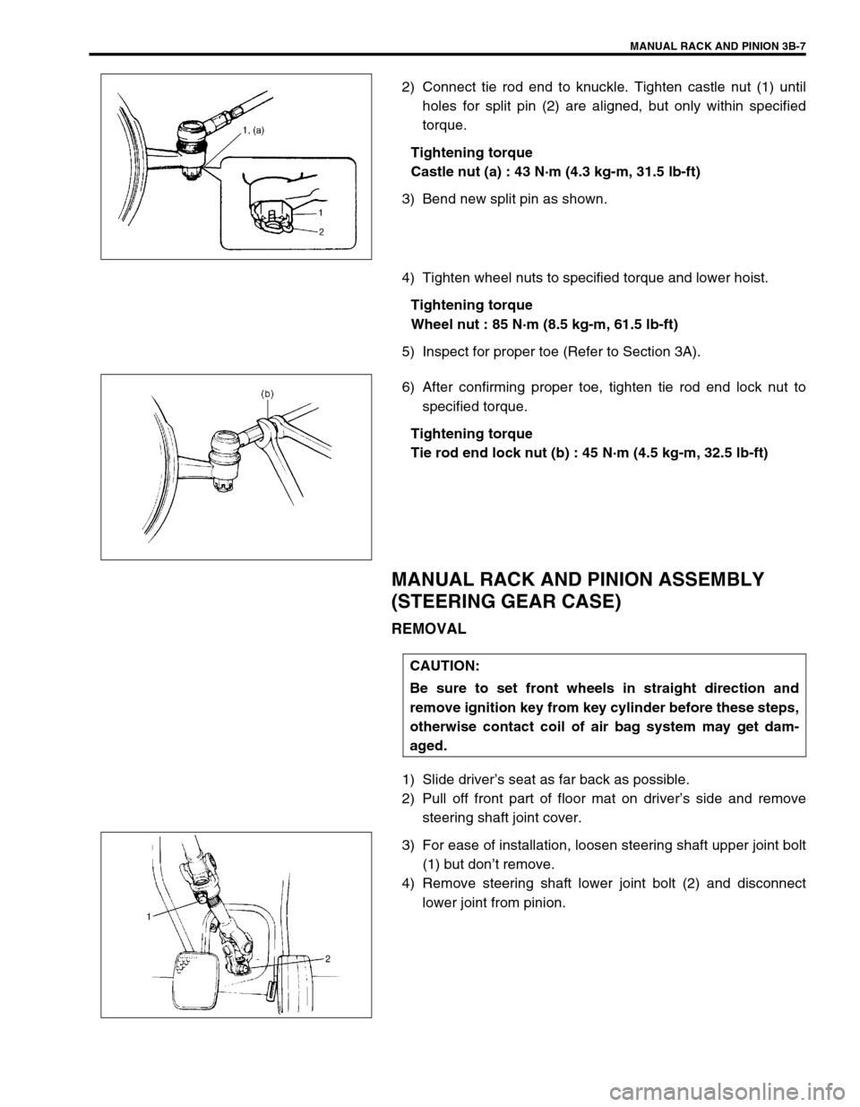
2) Connect tie rod end to knuckle. Tighten castle nut (1) until
holes for split pin (2) are aligned, but only within specified
torque.
Tightening torque
Castle nut (a) : 43 N·m (4.3 kg-m, 31.5 lb-ft)
3) Bend new split pin as shown.
4) Tighten wheel nuts to specified torque and lower hoist.
Tightening torque
Wheel nut : 85 N·m (8.5 kg-m, 61.5 lb-ft)
5) Inspect for proper toe (Refer to Section 3A).
6) After confirming proper toe, tighten tie rod end lock nut to
specified torque.
Tightening torque
Tie rod end lock nut (b) : 45 N·m (4.5 kg-m, 32.5 lb-ft)
MANUAL RACK AND PINION ASSEMBLY
(STEERING GEAR CASE)
REMOVAL
1) Slide driver’s seat as far back as possible.
2) Pull off front part of floor mat on driver’s side and remove
steering shaft joint cover.
3) For ease of installation, loosen steering shaft upper joint bolt
(1) but don’t remove.
4) Remove steering shaft lower joint bolt (2) and disconnect
lower joint from pinion.
CAUTION:
Be sure to set front wheels in straight direction and
remove ignition key from key cylinder before these steps,
otherwise contact coil of air bag system may get dam-
aged.
Page 129 of 698
3B-8 MANUAL RACK AND PINION
5) Hoist vehicle and remove both wheels.
6) Remove split pins (3) and tie rod castle nuts (2) from both
knuckles (1).
7) Disconnect both tie rod ends (2) from knuckles (1), using
special tool.
Special tool
(A) : 09913-65210
8) Remove exhaust No.1 pipe (1).
9) For ease of adjustment after installation, make marking of tie
rod end lock nut position on tie rod end thread. Then loosen
lock nut and remove tie rod end.
10) Remove steering gear case mount bolts (1) and gear case
brackets, then remove gear case (2).
1
NOTE:
For right-hand steering 4WD vehicle, before removing
steering gear case, remove transfer assembly referring
to Section 7D if necessary.
2
1
Page 131 of 698
3B-10 MANUAL RACK AND PINION
6) Reinstall cover (1) removed previously to steering shaft joint.
7) Put back floor mat as it was.
8) Install both wheels and tighten wheel nuts to specified
torque.
Tightening torque
Wheel nut : 85 N·m (8.5 kg-m, 61.5 lb-ft)
9) Lower hoist.
10) Check toe setting. Adjust as required (refer to Section 3A).
11) Tighten both tie rod end lock nuts to specified torque.
Tightening torque
Tie rod end lock nut (d) : 45 N·m (4.5 kg-m, 32.5 lb-ft)
RACK BOOT/TIE ROD
REMOVAL
1) Remove steering gear case by performing “MANUAL RACK
AND PINION ASSEMBLY REMOVAL” of this section.
2) For ease of adjustment after installation, make marking (1) of
tie rod end lock nut position of tie rod end thread.
3) Loosen tie rod end lock nut and remove tie rod end.
4) Remove boot wire (2) and clip (1).
5) Remove boot from tie rod.
Page 132 of 698
MANUAL RACK AND PINION 3B-11
6) Unbend bent part of tie rod lock washer (1) and remove tie
rod (2) from rack (3).
INSTALLATION
1) Install new tie rod lock washer (2) and tie rod (3) to rack (1).
Align straight part “A” of washer with flat part “B” of rack.
2) Tighten tie rod inside ball nut to specified torque.
Tightening torque
Tie rod inside ball nut (a) : 85 N·m (8.5 kg-m, 61.5 lb-ft)
3) Bend new lock washer to tie rod side as shown.
NOTE:
For correct installation of tie rod lock washer, referring to
the figure.
“B”: Upper
Page 133 of 698

3B-12 MANUAL RACK AND PINION
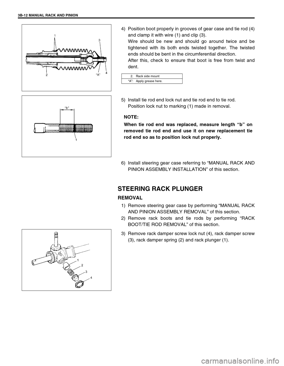
4) Position boot properly in grooves of gear case and tie rod (4)
and clamp it with wire (1) and clip (3).
Wire should be new and should go around twice and be
tightened with its both ends twisted together. The twisted
ends should be bent in the circumferential direction.
After this, check to ensure that boot is free from twist and
dent.
5) Install tie rod end lock nut and tie rod end to tie rod.
Position lock nut to marking (1) made in removal.
6) Install steering gear case referring to “MANUAL RACK AND
PINION ASSEMBLY INSTALLATION” of this section.
STEERING RACK PLUNGER
REMOVAL
1) Remove steering gear case by performing “MANUAL RACK
AND PINION ASSEMBLY REMOVAL” of this section.
2) Remove rack boots and tie rods by performing “RACK
BOOT/TIE ROD REMOVAL” of this section.
3) Remove rack damper screw lock nut (4), rack damper screw
(3), rack damper spring (2) and rack plunger (1).
2. Rack side mount
“A”: Apply grease here.
NOTE:
When tie rod end was replaced, measure length “b” on
removed tie rod end and use it on new replacement tie
rod end so as to position lock nut properly.
Page 134 of 698

MANUAL RACK AND PINION 3B-13
INSPECTION
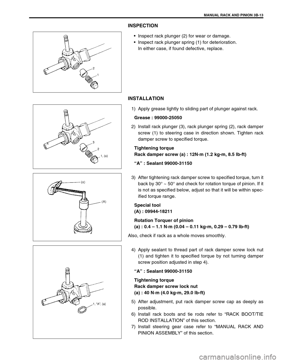
Inspect rack plunger (2) for wear or damage.
Inspect rack plunger spring (1) for deterioration.
In either case, if found defective, replace.
INSTALLATION
1) Apply grease lightly to sliding part of plunger against rack.
Grease : 99000-25050
2) Install rack plunger (3), rack plunger spring (2), rack damper
screw (1) to steering case in direction shown. Tighten rack
damper screw to specified torque.
Tightening torque
Rack damper screw (a) : 12N·m (1.2 kg-m, 8.5 lb-ft)
“A” : Sealant 99000-31150
3) After tightening rack damper screw to specified torque, turn it
back by 30° ~ 50° and check for rotation torque of pinion. If it
is not as specified below, adjust so that it will be within spec-
ified torque range.
Special tool
(A) : 09944-18211
Rotation Torquer of pinion
(a) : 0.4 – 1.1 N·m (0.04 – 0.11 kg-m, 0.29 – 0.79 lb-ft)
Also, check if rack as a whole moves smoothly.
4) Apply sealant to thread part of rack damper screw lock nut
(1) and tighten it to specified torque by not turning damper
screw position adjusted in step 4).
“A” : Sealant 99000-31150
Tightening torque
Rack damper screw lock nut
(a) : 40 N·m (4.0 kg-m, 29.0 lb-ft)
5) After adjustment, put rack damper screw cap as deeply as
possible.
6) Install rack boots and tie rods refer to “RACK BOOT/TIE
ROD INSTALLATION” of this section.
7) Install steering gear case refer to “MANUAL RACK AND
PINION ASSEMBLY” of this section.