2000 SUZUKI SWIFT lock
[x] Cancel search: lockPage 190 of 698
STEERING WHEEL AND COLUMN 3C-17
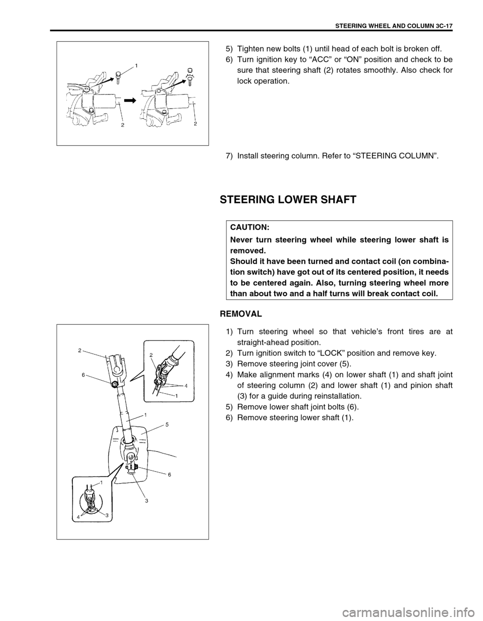
5) Tighten new bolts (1) until head of each bolt is broken off.
6) Turn ignition key to “ACC” or “ON” position and check to be
sure that steering shaft (2) rotates smoothly. Also check for
lock operation.
7) Install steering column. Refer to “STEERING COLUMN”.
STEERING LOWER SHAFT
REMOVAL
1) Turn steering wheel so that vehicle’s front tires are at
straight-ahead position.
2) Turn ignition switch to “LOCK” position and remove key.
3) Remove steering joint cover (5).
4) Make alignment marks (4) on lower shaft (1) and shaft joint
of steering column (2) and lower shaft (1) and pinion shaft
(3) for a guide during reinstallation.
5) Remove lower shaft joint bolts (6).
6) Remove steering lower shaft (1).
CAUTION:
Never turn steering wheel while steering lower shaft is
removed.
Should it have been turned and contact coil (on combina-
tion switch) have got out of its centered position, it needs
to be centered again. Also, turning steering wheel more
than about two and a half turns will break contact coil.
Page 250 of 698

WHEELS AND TIRES 3F-5
MAINTENANCE AND MINOR ADJUSTMENTS
WHEEL MAINTENANCE
Wheel repairs that use welding, heating, or peening are not approved. All damaged wheels should be replaced.
WHEEL ATTACHING STUDS
If a broken stud is found, see Section 3E (rear) or Section 3D (front) for Note and Replacement procedure.
MATCHED TIRES AND WHEELS
Tires and wheels are match mounted at the assembly plant.
This means that the radially stiffest part of the tire, or “high spot”,
is matched to the smallest radius or “low spot” of the wheel.
This is done to provide the smoothest possible ride.
The “high spot” of the tire is originally marked by paint dot (1) on
the outboard sidewall. This paint dot will eventually wash off the
tire.
The “ow spot” of the wheel is originally marked by paint dot (2) on
the wheel rim-flange. Properly assembled, the wheel rims’ paint
dot should be aligned with the tires’ paint dot as shown in left fig-
ure.
Whenever a tire is dismounted from its wheel, it should be
remounted so that the tire and wheel are matched. If the tire’s
paint dot cannot be located, a line should be scribed on the tire
and wheel before dismounting to assure that it is remounted in
the same position.
TIRE MAINTENANCE
TIRE PLACARD
The “Tire Placard” is located on the left door (right door for right-hand side steering vehicle) lock pillar and
should be referred to tire information.
The placard lists the maximum load, tire size and cold tire pressure where applicable.
NOTE:
Whether rim size and/or maximum load are listed or not depends on regulations of each country.
Page 251 of 698
3F-6 WHEELS AND TIRES
INFLATION OF TIRES
The pressure recommended for any model is carefully calculated to give a satisfactory ride, stability, steering,
tread wear, tire life and resistance to bruises.
Tire pressure, with tires cold, (after vehicle has set for 3 hours or more, or driven less than one mile) should be
checked monthly or before any extended trip. Set to the specifications on the “Tire Placard” located on the left
door (right door for right-hand side steering vehicle) lock pillar.
It is normal for tire pressure to increase when the tires become hot during driving.
Do not bleed or reduce tire pressure after driving. Bleeding reduces the “Cold Inflation Pressure”.
Higher than recommended pressure can cause :
Hard ride
Tire bruising or carcass damage
Rapid tread wear at center of tire
Unequal pressure on same axle can cause :
Uneven braking
Steering lead
Reduced handling
Swerve on acceleration
Lower than recommended pressure can cause :
Tire squeal on turns
Hard Steering
Rapid and uneven wear on the edges of the tread
Tire rim bruises and rupture
Tire cord breakage
High tire temperature
Reduced handling
High fuel consumption
TIRE ROTATION
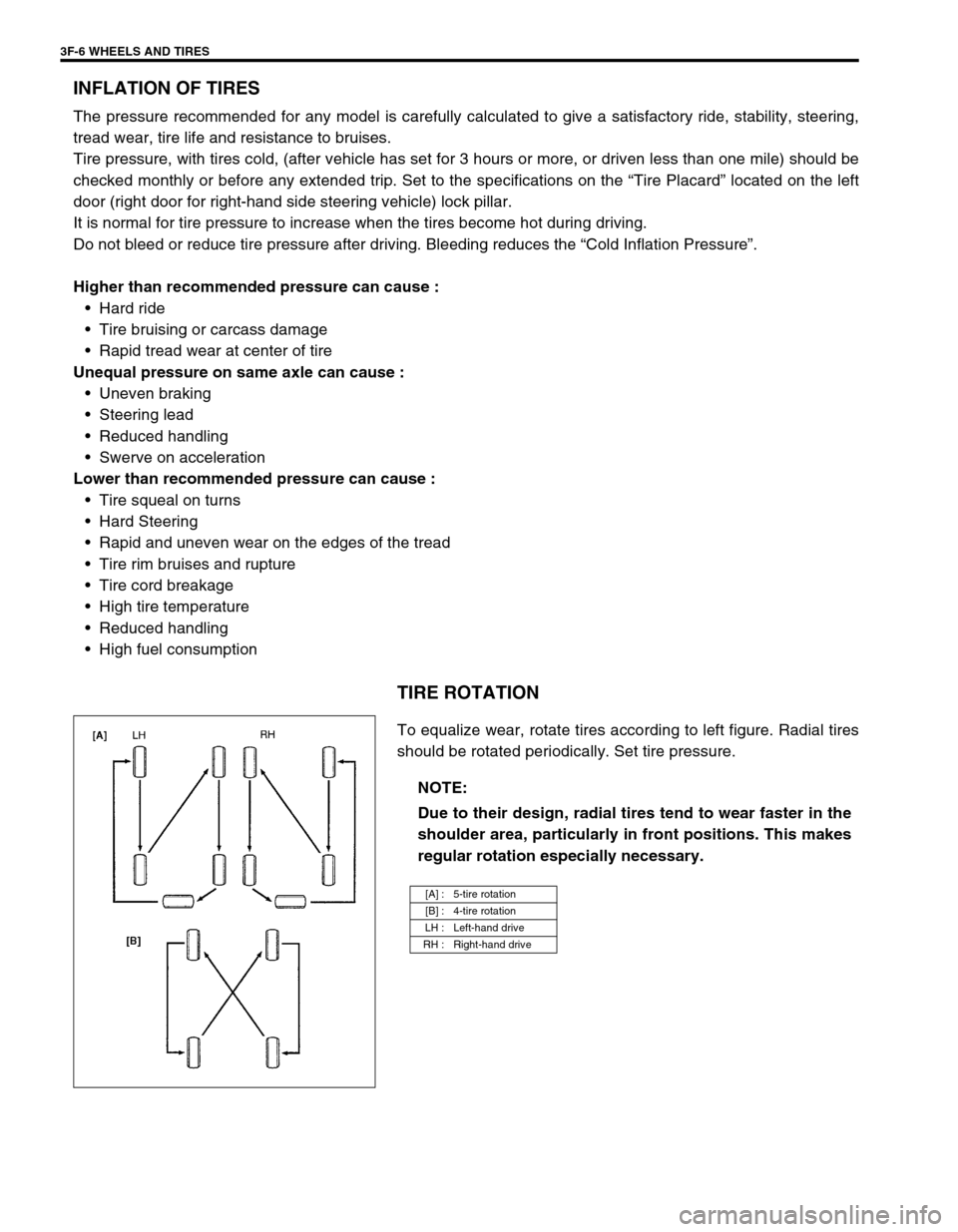
To equalize wear, rotate tires according to left figure. Radial tires
should be rotated periodically. Set tire pressure.
NOTE:
Due to their design, radial tires tend to wear faster in the
shoulder area, particularly in front positions. This makes
regular rotation especially necessary.
[A] : 5-tire rotation
[B] : 4-tire rotation
LH : Left-hand drive
RH : Right-hand drive
Page 278 of 698
BRAKES 5-5
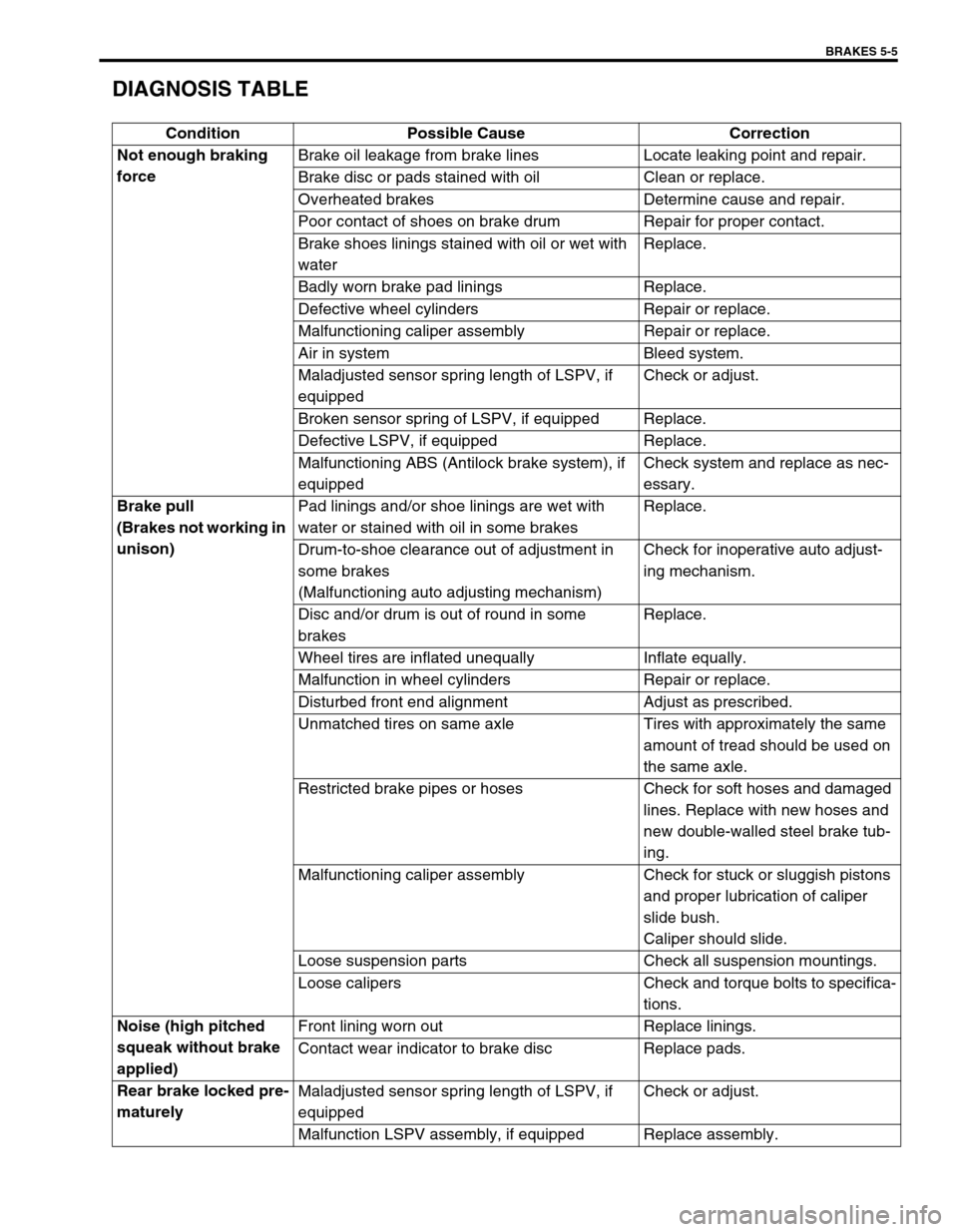
DIAGNOSIS TABLE
Condition Possible Cause Correction
Not enough braking
forceBrake oil leakage from brake lines Locate leaking point and repair.
Brake disc or pads stained with oil Clean or replace.
Overheated brakes Determine cause and repair.
Poor contact of shoes on brake drum Repair for proper contact.
Brake shoes linings stained with oil or wet with
waterReplace.
Badly worn brake pad linings Replace.
Defective wheel cylinders Repair or replace.
Malfunctioning caliper assembly Repair or replace.
Air in system Bleed system.
Maladjusted sensor spring length of LSPV, if
equippedCheck or adjust.
Broken sensor spring of LSPV, if equipped Replace.
Defective LSPV, if equipped Replace.
Malfunctioning ABS (Antilock brake system), if
equippedCheck system and replace as nec-
essary.
Brake pull
(Brakes not working in
unison)Pad linings and/or shoe linings are wet with
water or stained with oil in some brakesReplace.
Drum-to-shoe clearance out of adjustment in
some brakes
(Malfunctioning auto adjusting mechanism)Check for inoperative auto adjust-
ing mechanism.
Disc and/or drum is out of round in some
brakesReplace.
Wheel tires are inflated unequally Inflate equally.
Malfunction in wheel cylinders Repair or replace.
Disturbed front end alignment Adjust as prescribed.
Unmatched tires on same axle Tires with approximately the same
amount of tread should be used on
the same axle.
Restricted brake pipes or hoses Check for soft hoses and damaged
lines. Replace with new hoses and
new double-walled steel brake tub-
ing.
Malfunctioning caliper assembly Check for stuck or sluggish pistons
and proper lubrication of caliper
slide bush.
Caliper should slide.
Loose suspension parts Check all suspension mountings.
Loose calipers Check and torque bolts to specifica-
tions.
Noise (high pitched
squeak without brake
applied)Front lining worn out Replace linings.
Contact wear indicator to brake disc Replace pads.
Rear brake locked pre-
maturelyMaladjusted sensor spring length of LSPV, if
equippedCheck or adjust.
Malfunction LSPV assembly, if equipped Replace assembly.
Page 279 of 698
5-6 BRAKES
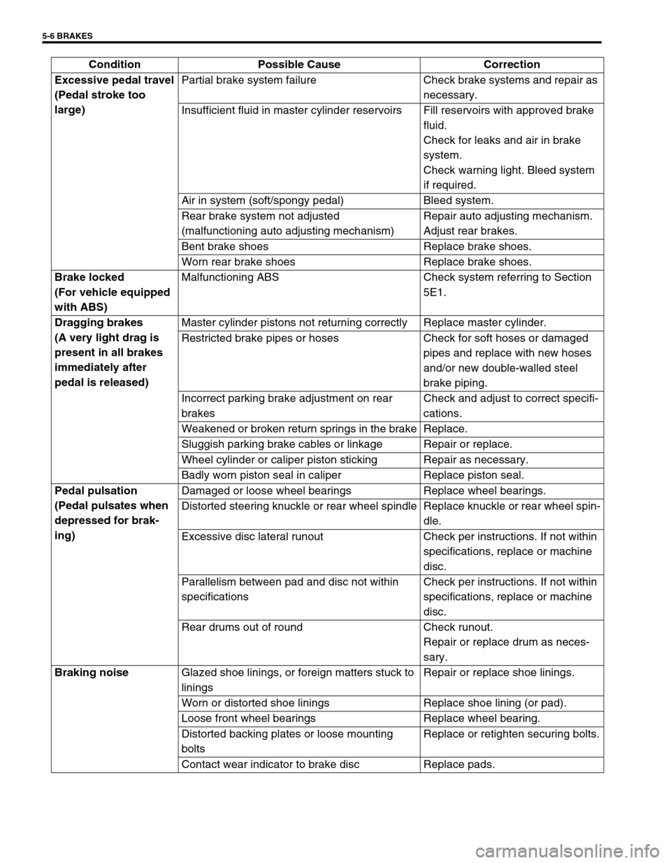
Excessive pedal travel
(Pedal stroke too
large)Partial brake system failure Check brake systems and repair as
necessary.
Insufficient fluid in master cylinder reservoirs Fill reservoirs with approved brake
fluid.
Check for leaks and air in brake
system.
Check warning light. Bleed system
if required.
Air in system (soft/spongy pedal) Bleed system.
Rear brake system not adjusted
(malfunctioning auto adjusting mechanism)Repair auto adjusting mechanism.
Adjust rear brakes.
Bent brake shoes Replace brake shoes.
Worn rear brake shoes Replace brake shoes.
Brake locked
(For vehicle equipped
with ABS)Malfunctioning ABS Check system referring to Section
5E1.
Dragging brakes
(A very light drag is
present in all brakes
immediately after
pedal is released)Master cylinder pistons not returning correctly Replace master cylinder.
Restricted brake pipes or hoses Check for soft hoses or damaged
pipes and replace with new hoses
and/or new double-walled steel
brake piping.
Incorrect parking brake adjustment on rear
brakesCheck and adjust to correct specifi-
cations.
Weakened or broken return springs in the brake Replace.
Sluggish parking brake cables or linkage Repair or replace.
Wheel cylinder or caliper piston sticking Repair as necessary.
Badly worn piston seal in caliper Replace piston seal.
Pedal pulsation
(Pedal pulsates when
depressed for brak-
ing)Damaged or loose wheel bearings Replace wheel bearings.
Distorted steering knuckle or rear wheel spindle Replace knuckle or rear wheel spin-
dle.
Excessive disc lateral runout Check per instructions. If not within
specifications, replace or machine
disc.
Parallelism between pad and disc not within
specificationsCheck per instructions. If not within
specifications, replace or machine
disc.
Rear drums out of round Check runout.
Repair or replace drum as neces-
sary.
Braking noise
Glazed shoe linings, or foreign matters stuck to
liningsRepair or replace shoe linings.
Worn or distorted shoe linings Replace shoe lining (or pad).
Loose front wheel bearings Replace wheel bearing.
Distorted backing plates or loose mounting
boltsReplace or retighten securing bolts.
Contact wear indicator to brake disc Replace pads. Condition Possible Cause Correction
Page 281 of 698
5-8 BRAKES
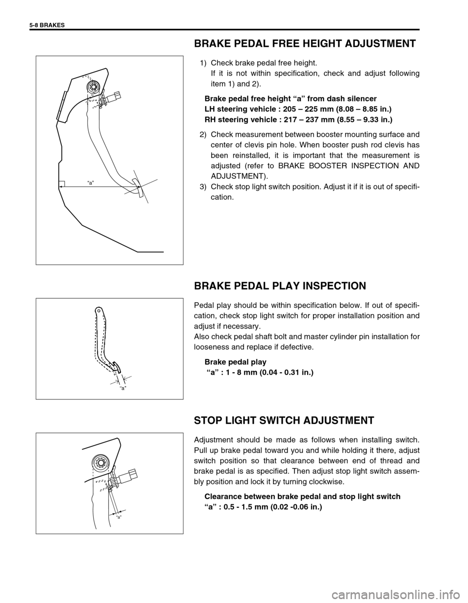
BRAKE PEDAL FREE HEIGHT ADJUSTMENT
1) Check brake pedal free height.
If it is not within specification, check and adjust following
item 1) and 2).
Brake pedal free height “a” from dash silencer
LH steering vehicle : 205 – 225 mm (8.08 – 8.85 in.)
RH steering vehicle : 217 – 237 mm (8.55 – 9.33 in.)
2) Check measurement between booster mounting surface and
center of clevis pin hole. When booster push rod clevis has
been reinstalled, it is important that the measurement is
adjusted (refer to BRAKE BOOSTER INSPECTION AND
ADJUSTMENT).
3) Check stop light switch position. Adjust it if it is out of specifi-
cation.
BRAKE PEDAL PLAY INSPECTION
Pedal play should be within specification below. If out of specifi-
cation, check stop light switch for proper installation position and
adjust if necessary.
Also check pedal shaft bolt and master cylinder pin installation for
looseness and replace if defective.
Brake pedal play
“a” : 1 - 8 mm (0.04 - 0.31 in.)
STOP LIGHT SWITCH ADJUSTMENT
Adjustment should be made as follows when installing switch.
Pull up brake pedal toward you and while holding it there, adjust
switch position so that clearance between end of thread and
brake pedal is as specified. Then adjust stop light switch assem-
bly position and lock it by turning clockwise.
Clearance between brake pedal and stop light switch
“a” : 0.5 - 1.5 mm (0.02 -0.06 in.)
“a”
“a”
Page 283 of 698
5-10 BRAKES
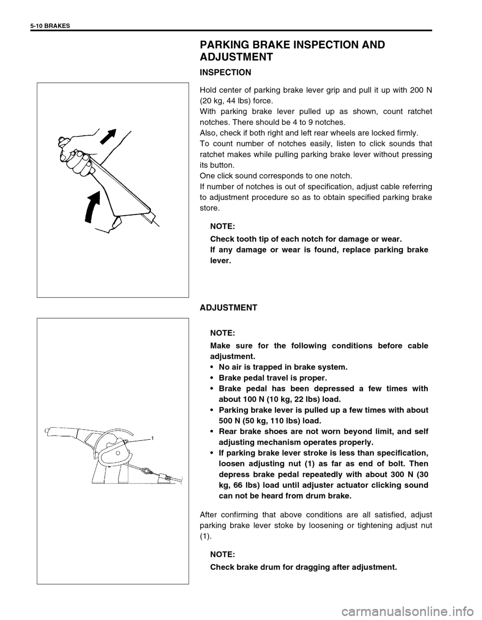
PARKING BRAKE INSPECTION AND
ADJUSTMENT
INSPECTION
Hold center of parking brake lever grip and pull it up with 200 N
(20 kg, 44 lbs) force.
With parking brake lever pulled up as shown, count ratchet
notches. There should be 4 to 9 notches.
Also, check if both right and left rear wheels are locked firmly.
To count number of notches easily, listen to click sounds that
ratchet makes while pulling parking brake lever without pressing
its button.
One click sound corresponds to one notch.
If number of notches is out of specification, adjust cable referring
to adjustment procedure so as to obtain specified parking brake
store.
ADJUSTMENT
After confirming that above conditions are all satisfied, adjust
parking brake lever stoke by loosening or tightening adjust nut
(1).NOTE:
Check tooth tip of each notch for damage or wear.
If any damage or wear is found, replace parking brake
lever.
NOTE:
Make sure for the following conditions before cable
adjustment.
No air is trapped in brake system.
Brake pedal travel is proper.
Brake pedal has been depressed a few times with
about 100 N (10 kg, 22 lbs) load.
Parking brake lever is pulled up a few times with about
500 N (50 kg, 110 lbs) load.
Rear brake shoes are not worn beyond limit, and self
adjusting mechanism operates properly.
If parking brake lever stroke is less than specification,
loosen adjusting nut (1) as far as end of bolt. Then
depress brake pedal repeatedly with about 300 N (30
kg, 66 lbs) load until adjuster actuator clicking sound
can not be heard from drum brake.
NOTE:
Check brake drum for dragging after adjustment.
Page 313 of 698

5-40 BRAKES
INSPECTION AND ADJUSTMENT
Installation Position Of Push Rod
If push rod clevis (1) has been removed, adjust distance between
booster installation surface (without including packing) and the
center of clevis pin hole to standard value “a” and tighten nut (2)
to specified torque.
Distance “a” between center of booster clevis pin hole
and booster surface
Standard : 97 - 98 mm (3.82 - 3.86 in.)
Tightening torque
Clevis pin lock nut (a) : 19 N·m (1.9 kg-m, 14.0 lb-ft)
Clearance Between Booster Piston Rod And Master Cylin-
der Piston
The length of booster piston rod (1) is adjusted to provide speci-
fied clearance “a” between piston rod (1) end and master cylinder
piston (2).
Before measuring clearance, push piston rod several times
so as to make sure reaction disc is in place.
Keep inside of booster at atmospheric pressure for measure-
ment.
Measure length “a” of piston rod, i.e. distance between piston rod
and mating surface of booster-to-master cylinder.
Length “a” of piston rod
: 30.3 - 30.5 mm (1.193 - 1.200 in.)
If measurement is out of specification, adjust piston rod by turning
adjusting screw of piston rod.
Special tool
(B) : 09952-16020
NOTE:
Remove gasket from booster, if equipped.