Page 140 of 698
MANUAL RACK AND PINION 3B-19
INSTALLATION
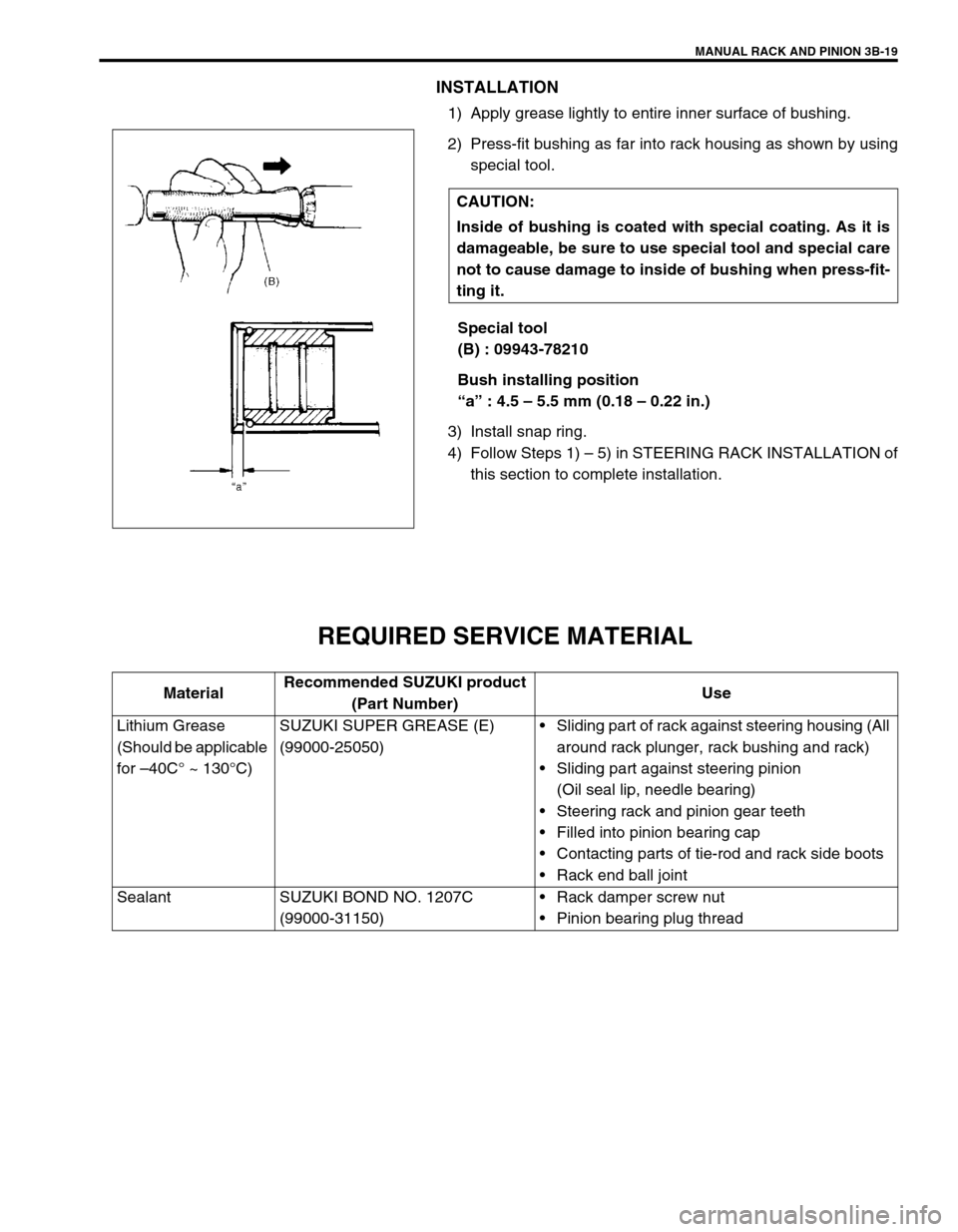
1) Apply grease lightly to entire inner surface of bushing.
2) Press-fit bushing as far into rack housing as shown by using
special tool.
Special tool
(B) : 09943-78210
Bush installing position
“a” : 4.5 – 5.5 mm (0.18 – 0.22 in.)
3) Install snap ring.
4) Follow Steps 1) – 5) in STEERING RACK INSTALLATION of
this section to complete installation.
REQUIRED SERVICE MATERIAL
CAUTION:
Inside of bushing is coated with special coating. As it is
damageable, be sure to use special tool and special care
not to cause damage to inside of bushing when press-fit-
ting it.
MaterialRecommended SUZUKI product
(Part Number)Use
Lithium Grease
(Should be applicable
for –40C° ~ 130°C)SUZUKI SUPER GREASE (E)
(99000-25050)Sliding part of rack against steering housing (All
around rack plunger, rack bushing and rack)
Sliding part against steering pinion
(Oil seal lip, needle bearing)
Steering rack and pinion gear teeth
Filled into pinion bearing cap
Contacting parts of tie-rod and rack side boots
Rack end ball joint
Sealant SUZUKI BOND NO. 1207C
(99000-31150)Rack damper screw nut
Pinion bearing plug thread
Page 160 of 698
ELECTRICAL POWER STEERING (P/S) SYSTEM 3B1-19
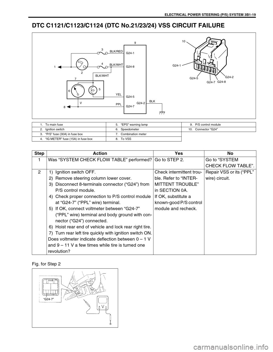
DTC C1121/C1123/C1124 (DTC No.21/23/24) VSS CIRCUIT FAILURE
Fig. for Step 2
1. To main fuse 5.“EPS” warning lamp 9. P/S control module
2. Ignition switch 6. Speedometer 10. Connector “G24”
3.“P/S” fuse (30A) in fuse box 7. Combination meter
4.“IG METER” fuse (15A) in fuse box 8. To VSS
G24-2 G24-1
G24-8
G24-7 G24-5 1
23
4
5
67
89
BLK/WHT
BLK/WHTBLK/RED
YEL
PPL VBLK
G24-1
G24-5
G24-7G24-8G24-2
10
Step Action Yes No
1Was “SYSTEM CHECK FLOW TABLE” performed? Go to STEP 2. Go to “SYSTEM
CHECK FLOW TABLE”.
2 1) Ignition switch OFF.
2) Remove steering column lower cover.
3) Disconnect 8-terminals connector (“G24”) from
P/S control module.
4) Check proper connection to P/S control module
at “G24-7” (“PPL” wire) terminal.
5) If OK, connect voltmeter between “G24-7”
(“PPL” wire) terminal and body ground with con-
nector (“G24”) connected.
6) Hoist rear end of vehicle and lock rear right tire.
7) Turn rear left tire quickly with ignition switch ON.
Does voltmeter indicate deflection between 0 – 1 V
and 9 – 11 V a few times while tire is turned one
revolution?Check intermittent trou-
ble. Refer to “INTER-
MITTENT TROUBLE”
in SECTION 0A.
If OK, substitute a
known-good P/S control
module and recheck.Repair VSS or its (“PPL”
wire) circuit.
Page 168 of 698
ELECTRICAL POWER STEERING (P/S) SYSTEM 3B1-27
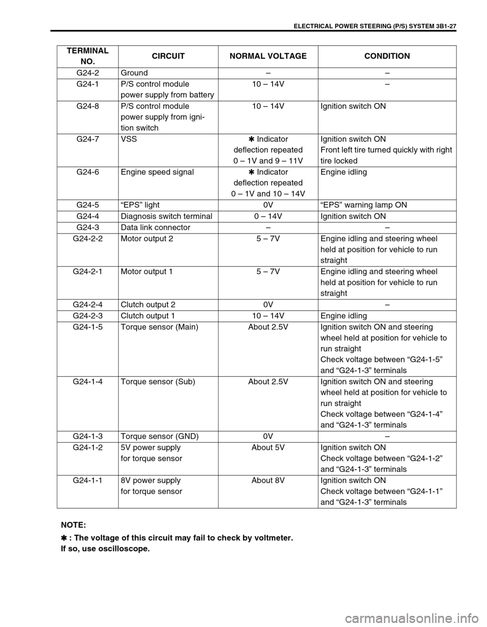
TERMINAL
NO.CIRCUIT NORMAL VOLTAGE CONDITION
G24-2 Ground––
G24-1 P/S control module
power supply from battery10 – 14V–
G24-8 P/S control module
power supply from igni-
tion switch10 – 14V Ignition switch ON
G24-7 VSS✱ Indicator
deflection repeated
0 – 1V and 9 – 11VIgnition switch ON
Front left tire turned quickly with right
tire locked
G24-6 Engine speed signal✱ Indicator
deflection repeated
0 – 1V and 10 – 14VEngine idling
G24-5“EPS” light 0V“EPS” warning lamp ON
G24-4 Diagnosis switch terminal 0 – 14V Ignition switch ON
G24-3 Data link connector––
G24-2-2 Motor output 2 5 – 7V Engine idling and steering wheel
held at position for vehicle to run
straight
G24-2-1 Motor output 1 5 – 7V Engine idling and steering wheel
held at position for vehicle to run
straight
G24-2-4 Clutch output 2 0V–
G24-2-3 Clutch output 1 10 – 14V Engine idling
G24-1-5 Torque sensor (Main) About 2.5V Ignition switch ON and steering
wheel held at position for vehicle to
run straight
Check voltage between “G24-1-5”
and “G24-1-3” terminals
G24-1-4 Torque sensor (Sub) About 2.5V Ignition switch ON and steering
wheel held at position for vehicle to
run straight
Check voltage between “G24-1-4”
and “G24-1-3” terminals
G24-1-3 Torque sensor (GND) 0V–
G24-1-2 5V power supply
for torque sensorAbout 5V Ignition switch ON
Check voltage between “G24-1-2”
and “G24-1-3” terminals
G24-1-1 8V power supply
for torque sensorAbout 8V Ignition switch ON
Check voltage between “G24-1-1”
and “G24-1-3” terminals
NOTE:
✱
✱✱ ✱ : The voltage of this circuit may fail to check by voltmeter.
If so, use oscilloscope.
Page 169 of 698
3B1-28 ELECTRICAL POWER STEERING (P/S) SYSTEM
STEERING WHEEL PLAY INSPECTION
Check steering wheel for looseness or rattle by trying to move it in
its shaft direction and lateral direction.
If found defective, repair or replace.
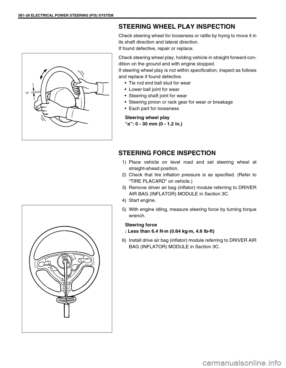
Check steering wheel play, holding vehicle in straight forward con-
dition on the ground and with engine stopped.
If steering wheel play is not within specification, inspect as follows
and replace if found defective.
Tie rod end ball stud for wear
Lower ball joint for wear
Steering shaft joint for wear
Steering pinion or rack gear for wear or breakage
Each part for looseness
Steering wheel play
“a”: 0 - 30 mm (0 - 1.2 in.)
STEERING FORCE INSPECTION
1) Place vehicle on level road and set steering wheel at
straight-ahead position.
2) Check that tire inflation pressure is as specified. (Refer to
“TIRE PLACARD” on vehicle.)
3) Remove driver air bag (inflator) module referring to DRIVER
AIR BAG (INFLATOR) MODULE in Section 3C.
4) Start engine.
5) With engine idling, measure steering force by turning torque
wrench.
Steering force
: Less than 6.4 N·m (0.64 kg·m, 4.6 lb-ft)
6) Install drive air bag (inflator) module referring to DRIVER AIR
BAG (INFLATOR) MODULE in Section 3C.
Page 180 of 698
STEERING WHEEL AND COLUMN 3C-7
INSTALLATION
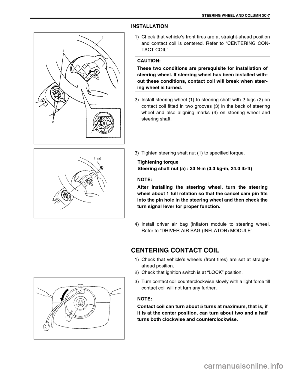
1) Check that vehicle’s front tires are at straight-ahead position
and contact coil is centered. Refer to “CENTERING CON-
TACT COIL”.
2) Install steering wheel (1) to steering shaft with 2 lugs (2) on
contact coil fitted in two grooves (3) in the back of steering
wheel and also aligning marks (4) on steering wheel and
steering shaft.
3) Tighten steering shaft nut (1) to specified torque.
Tightening torque
Steering shaft nut (a) : 33 N·m (3.3 kg-m, 24.0 lb-ft)
4) Install driver air bag (inflator) module to steering wheel.
Refer to “DRIVER AIR BAG (INFLATOR) MODULE”.
CENTERING CONTACT COIL
1) Check that vehicle’s wheels (front tires) are set at straight-
ahead position.
2) Check that ignition switch is at “LOCK” position.
3) Turn contact coil counterclockwise slowly with a light force till
contact coil will not turn any further. CAUTION:
These two conditions are prerequisite for installation of
steering wheel. If steering wheel has been installed with-
out these conditions, contact coil will break when steer-
ing wheel is turned.
NOTE:
After installing the steering wheel, turn the steering
wheel about 1 full rotation so that the cancel cam pin fits
into the pin hole in the steering wheel and then check the
turn signal lever for proper function.
NOTE:
Contact coil can turn about 5 turns at maximum, that is, if
it is at the center position, can turn about two and a half
turns both clockwise and counterclockwise.
Page 182 of 698
STEERING WHEEL AND COLUMN 3C-9
5) Remove contact coil and combination switch assembly
screws (1) and disconnect connectors (2) from combination
switch (3).
6) Disconnect horn connector (1) from instrument panel har-
ness.
7) Remove contact coil and combination switch assembly from
steering column.
INSPECTION
Check contact coil harness (1) for any signs of scorching, melting
or other damage.
If it is damaged, replace.
INSTALLATION
1) Check to make sure that vehicle’s front tires are set at
straight-ahead position and then ignition switch is at “LOCK”
position.
2) Connect all connectors disconnected in REMOVAL.
Page 184 of 698
STEERING WHEEL AND COLUMN 3C-11
REMOVAL
1) Disconnect negative cable at battery.
2) Disable air bag system. Refer to “DISABLING AIR BAG
SYSTEM” under “SERVICE PRECAUTIONS” in Section
10B.
3) If it is necessary to remove steering wheel and contact coil
and combination switch assembly, remove them, referring to
“STEERING WHEEL” and “CONTACT COIL AND COMBI-
NATION SWITCH ASSEMBLY”.
If it is not necessary to remove steering wheel and contact
coil and combination switch assembly, perform the following
procedure.
a) Turn steering wheel so that vehicle’s front tires are at
straight-ahead position.
b) Turn ignition switch to “LOCK” position and remove key.
4) Remove steering column hole cover (1).
5) Loosen steering column mounting nuts (“A”, “B”). WARNING:
Never rest a steering column assembly on the steering
wheel with the air bag (inflator) module face down and
column vertical. Otherwise, personal injury may result.
1
Page 190 of 698
STEERING WHEEL AND COLUMN 3C-17
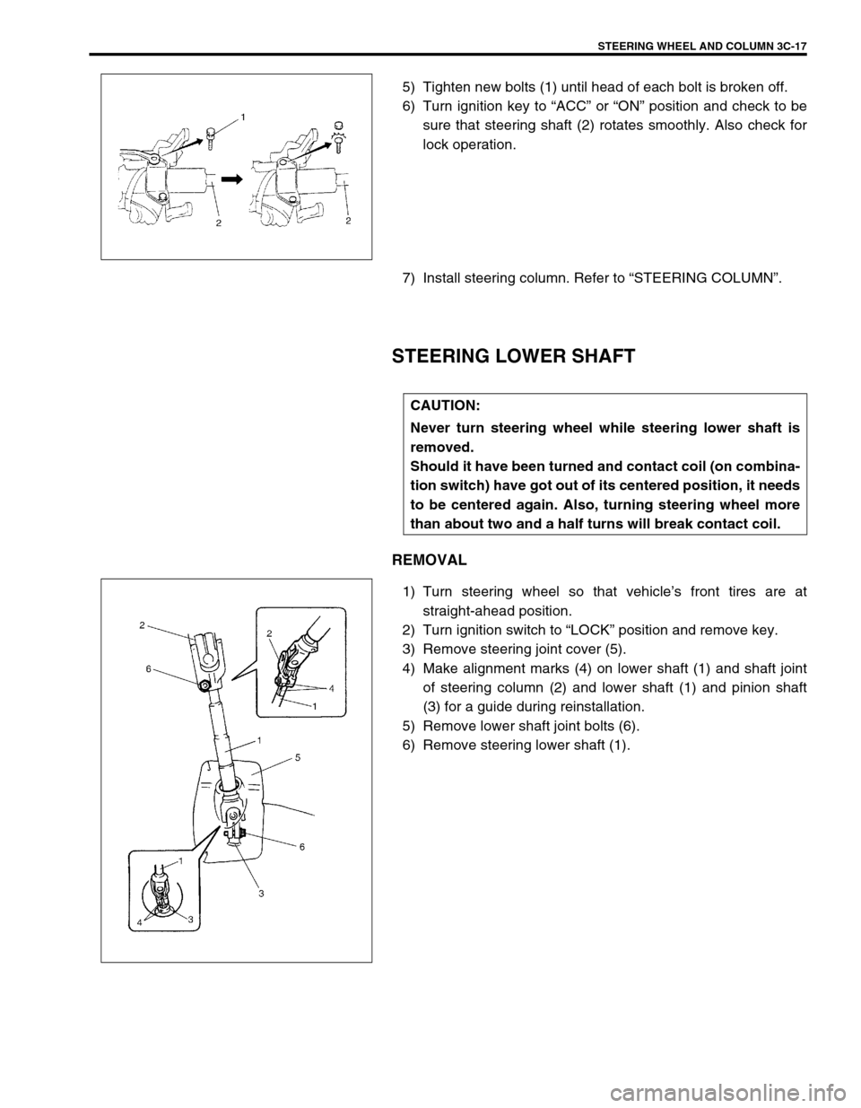
5) Tighten new bolts (1) until head of each bolt is broken off.
6) Turn ignition key to “ACC” or “ON” position and check to be
sure that steering shaft (2) rotates smoothly. Also check for
lock operation.
7) Install steering column. Refer to “STEERING COLUMN”.
STEERING LOWER SHAFT
REMOVAL
1) Turn steering wheel so that vehicle’s front tires are at
straight-ahead position.
2) Turn ignition switch to “LOCK” position and remove key.
3) Remove steering joint cover (5).
4) Make alignment marks (4) on lower shaft (1) and shaft joint
of steering column (2) and lower shaft (1) and pinion shaft
(3) for a guide during reinstallation.
5) Remove lower shaft joint bolts (6).
6) Remove steering lower shaft (1).
CAUTION:
Never turn steering wheel while steering lower shaft is
removed.
Should it have been turned and contact coil (on combina-
tion switch) have got out of its centered position, it needs
to be centered again. Also, turning steering wheel more
than about two and a half turns will break contact coil.