Page 256 of 698

FRONT DRIVE SHAFT 4A-3
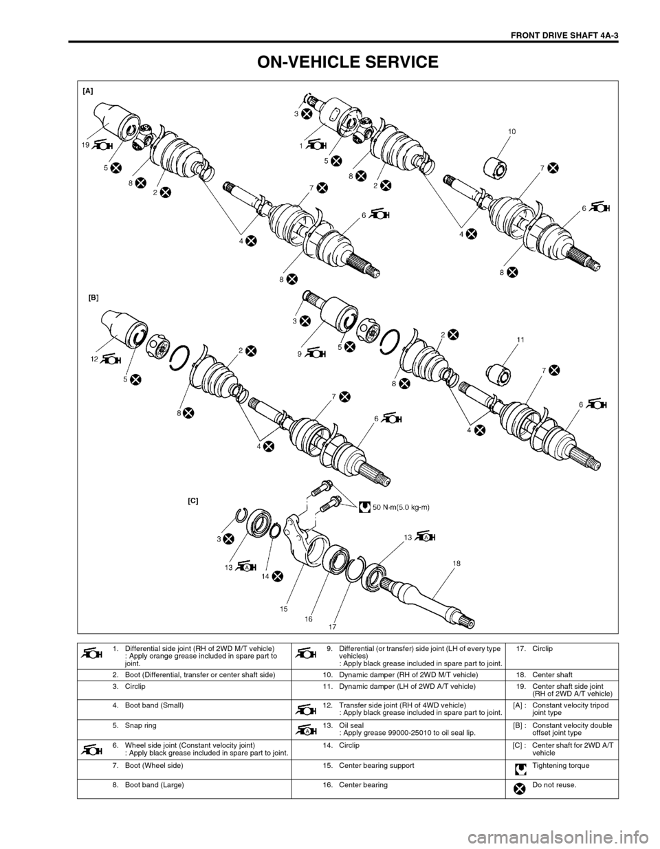
ON-VEHICLE SERVICE
1. Differential side joint (RH of 2WD M/T vehicle)
: Apply orange grease included in spare part to
joint.9. Differential (or transfer) side joint (LH of every type
vehicles)
: Apply black grease included in spare part to joint.17. Circlip
2. Boot (Differential, transfer or center shaft side) 10. Dynamic damper (RH of 2WD M/T vehicle) 18. Center shaft
3. Circlip 11. Dynamic damper (LH of 2WD A/T vehicle) 19. Center shaft side joint
(RH of 2WD A/T vehicle)
4. Boot band (Small) 12. Transfer side joint (RH of 4WD vehicle)
: Apply black grease included in spare part to joint.[A] : Constant velocity tripod
joint type
5. Snap ring 13. Oil seal
: Apply grease 99000-25010 to oil seal lip.[B] : Constant velocity double
offset joint type
6. Wheel side joint (Constant velocity joint)
: Apply black grease included in spare part to joint.14. Circlip [C] : Center shaft for 2WD A/T
vehicle
7. Boot (Wheel side) 15. Center bearing support Tightening torque
8. Boot band (Large) 16. Center bearing Do not reuse.
Page 257 of 698

4A-4 FRONT DRIVE SHAFT
DRIVE SHAFT ASSEMBLY
REMOVAL
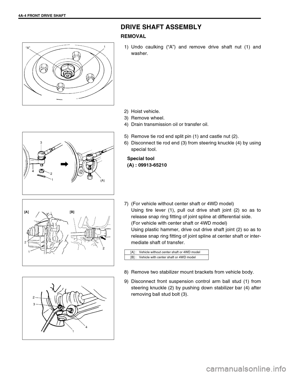
1) Undo caulking (“A”) and remove drive shaft nut (1) and
washer.
2) Hoist vehicle.
3) Remove wheel.
4) Drain transmission oil or transfer oil.
5) Remove tie rod end split pin (1) and castle nut (2).
6) Disconnect tie rod end (3) from steering knuckle (4) by using
special tool.
Special tool
(A) : 09913-65210
7) (For vehicle without center shaft or 4WD model)
Using tire lever (1), pull out drive shaft joint (2) so as to
release snap ring fitting of joint spline at differential side.
(For vehicle with center shaft or 4WD model)
Using plastic hammer, drive out drive shaft joint (2) so as to
release snap ring fitting of joint spline at center shaft or inter-
mediate shaft of transfer.
8) Remove two stabilizer mount brackets from vehicle body.
9) Disconnect front suspension control arm ball stud (1) from
steering knuckle (2) by pushing down stabilizer bar (4) after
removing ball stud bolt (3).
[A] : Vehicle without center shaft or 4WD model
[B] : Vehicle with center shaft or 4WD model
Page 258 of 698
FRONT DRIVE SHAFT 4A-5
10) Remove drive shaft assembly.
11) For vehicle with center shaft
Remove center bearing support bolts (3) and remove center
bearing support (2) with center shaft (1) from differential side
gear.
DISASSEMBLY
For Tripod Joint Type Drive Shaft
1) Remove differential side boot band, then take out tripod joint
housing (1).
2) Remove grease from shaft and take off snap ring (1) by
using special tool, then pull out spider (2) from shaft.
Special tool
(A) : 09900-06107 CAUTION:
To prevent breakage of boots, be careful not to bring
them into contact with other parts, when removing drive
shaft assembly.
3
2
1
CAUTION:
To prevent needle bearing of joint from being degreased,
do not wash it if it is to be reused.
Page 259 of 698
4A-6 FRONT DRIVE SHAFT
3) Remove boot band, then pull out differential side boot from
shaft.
4) Pull out damper through shaft. (if equipped)
5) Undo boot bands of wheel side joint boot, then pull out boot
through shaft.
For DOJ Type Drive Shaft
1) Remove boot band (1) of differential side joint.
2) Slide boot (1) toward the center of shaft and remove snap
ring (2) from outer race, then take shaft out of outer race (3).
3) Wipe off grease and remove circlip (1) used to fix cage by
using special tool (A).
Special tool
(A) : 09900-06107 CAUTION:
Disassembly of wheel side joint is not allowed. If noise
or damage exists in it, replace it as assembly.
Do not disassemble tripod joint spider. If any malcon-
dition is found in it, replace it as differential side joint
assembly.
Page 260 of 698
FRONT DRIVE SHAFT 4A-7
4) Draw away cage (1) by using bearing puller (2), and remove
boot (3) from shaft.
5) Remove boot band, then pull out differential side boot from
shaft.
6) Pull out damper through shaft. (if equipped)
7) Undo boot bands of wheel side joint boot, then pull out boot
through shaft.
For Center Shaft and Center Bearing Support
1) Remove right side oil seal from center bearing support (1).
2) Remove circlip by using special tool.
Special tool
(A) : 09900-06108
3) Using hydraulic press (1), draw out center shaft (2) from cen-
ter bearing.
4) Remove left side oil seal from center bearing support (3).
CAUTION:
Do not disassemble wheel side joint. If any malcondition
is found in any joint, replace it as assembly.
Page 261 of 698

4A-8 FRONT DRIVE SHAFT
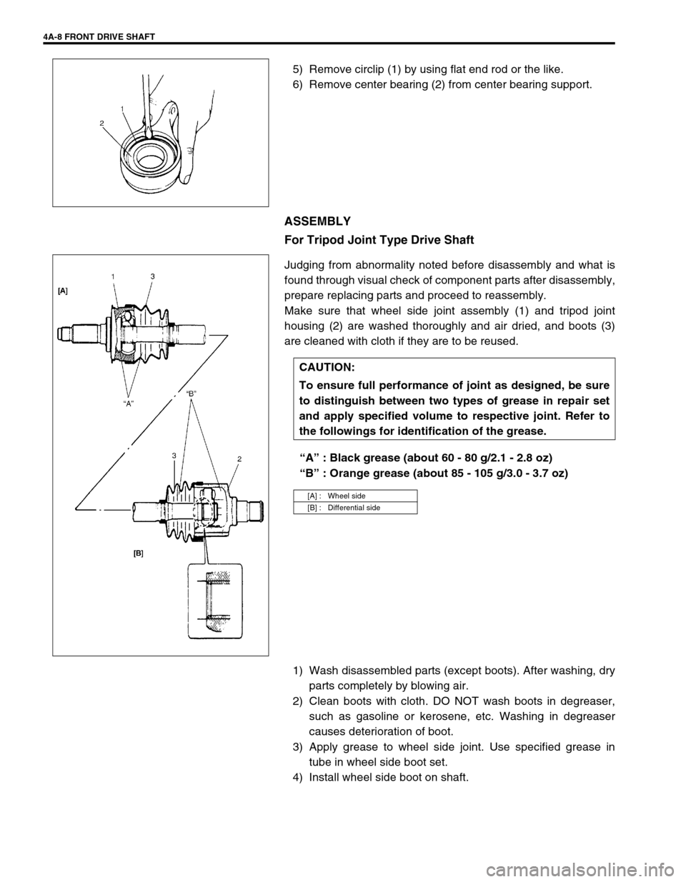
5) Remove circlip (1) by using flat end rod or the like.
6) Remove center bearing (2) from center bearing support.
ASSEMBLY
For Tripod Joint Type Drive Shaft
Judging from abnormality noted before disassembly and what is
found through visual check of component parts after disassembly,
prepare replacing parts and proceed to reassembly.
Make sure that wheel side joint assembly (1) and tripod joint
housing (2) are washed thoroughly and air dried, and boots (3)
are cleaned with cloth if they are to be reused.
“A” : Black grease (about 60 - 80 g/2.1 - 2.8 oz)
“B” : Orange grease (about 85 - 105 g/3.0 - 3.7 oz)
1) Wash disassembled parts (except boots). After washing, dry
parts completely by blowing air.
2) Clean boots with cloth. DO NOT wash boots in degreaser,
such as gasoline or kerosene, etc. Washing in degreaser
causes deterioration of boot.
3) Apply grease to wheel side joint. Use specified grease in
tube in wheel side boot set.
4) Install wheel side boot on shaft.
CAUTION:
To ensure full performance of joint as designed, be sure
to distinguish between two types of grease in repair set
and apply specified volume to respective joint. Refer to
the followings for identification of the grease.
[A] : Wheel side
[B] : Differential side
Page 262 of 698

FRONT DRIVE SHAFT 4A-9
5) Fill up boot inside with specified grease and then fasten boot
with bands (1).
6) Install dynamic damper (1) on drive shaft according to
dimension specified below.
Drive shaft dynamic damper installing position
“a” : 347 - 353 mm (13.7 - 13.9 in.)
7) Set new differential side small band and differential side boot
(1) on shaft temporarily.
Apply grease to tripod joint (2). Use specified grease in tube
included in spare parts.
8) Install tripod joint spider (3) on shaft, facing its chamfered
spline inward (wheel side), then fasten it with snap ring (4).
Special tool
(A) : 09900-06107
9) Apply grease to inside of outer race (1), then install housing,
joint it with boot and fit boot to outer race.
After fitting boot, insert screwdriver into boot on outer race
side and allow air to enter boot so that air pressure in boot
becomes the same as atmospheric pressure. CAUTION:
Bend each boot band against forward rotation (A).
Do not squeeze or distort boot when fastening it with
bands.
Distorted boot caused by squeezing air may reduce its
durability.
Page 263 of 698
4A-10 FRONT DRIVE SHAFT
10) When fixing boot (1) to outer race (2) with differential side big
band (3), adjust so that measured dimensions become as
indicated below.
Drive shaft boot fixing position
“a” : 155.5 mm (6.12 in.) for M/T vehicle
“b” : 189.3 mm (7.45 in.) for A/T vehicle
CAUTION:
To prevent any problem caused by washing solution, do
not wash joint boots and tripod joint except its housing.
Degreasing of those parts with cloth is allowed.
[A] : Wheel side
[B] : Differential side
CAUTION:
Bend each boot band against forward rotation.
Do not squeeze or distort boot when fastening it with
bands.
Distorted boot caused by squeezing air may reduce its
durability.