Page 507 of 698
6A1-6 ENGINE MECHANICAL (M13 ENGINE)
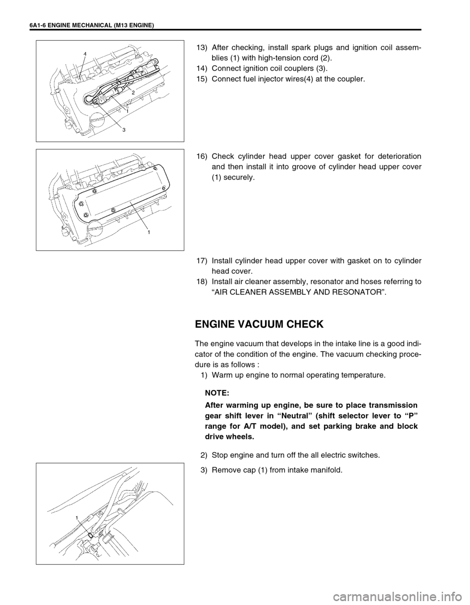
13) After checking, install spark plugs and ignition coil assem-
blies (1) with high-tension cord (2).
14) Connect ignition coil couplers (3).
15) Connect fuel injector wires(4) at the coupler.
16) Check cylinder head upper cover gasket for deterioration
and then install it into groove of cylinder head upper cover
(1) securely.
17) Install cylinder head upper cover with gasket on to cylinder
head cover.
18) Install air cleaner assembly, resonator and hoses referring to
“AIR CLEANER ASSEMBLY AND RESONATOR”.
ENGINE VACUUM CHECK
The engine vacuum that develops in the intake line is a good indi-
cator of the condition of the engine. The vacuum checking proce-
dure is as follows :
1) Warm up engine to normal operating temperature.
2) Stop engine and turn off the all electric switches.
3) Remove cap (1) from intake manifold.
NOTE:
After warming up engine, be sure to place transmission
gear shift lever in “Neutral” (shift selector lever to “P”
range for A/T model), and set parking brake and block
drive wheels.
Page 509 of 698
6A1-8 ENGINE MECHANICAL (M13 ENGINE)
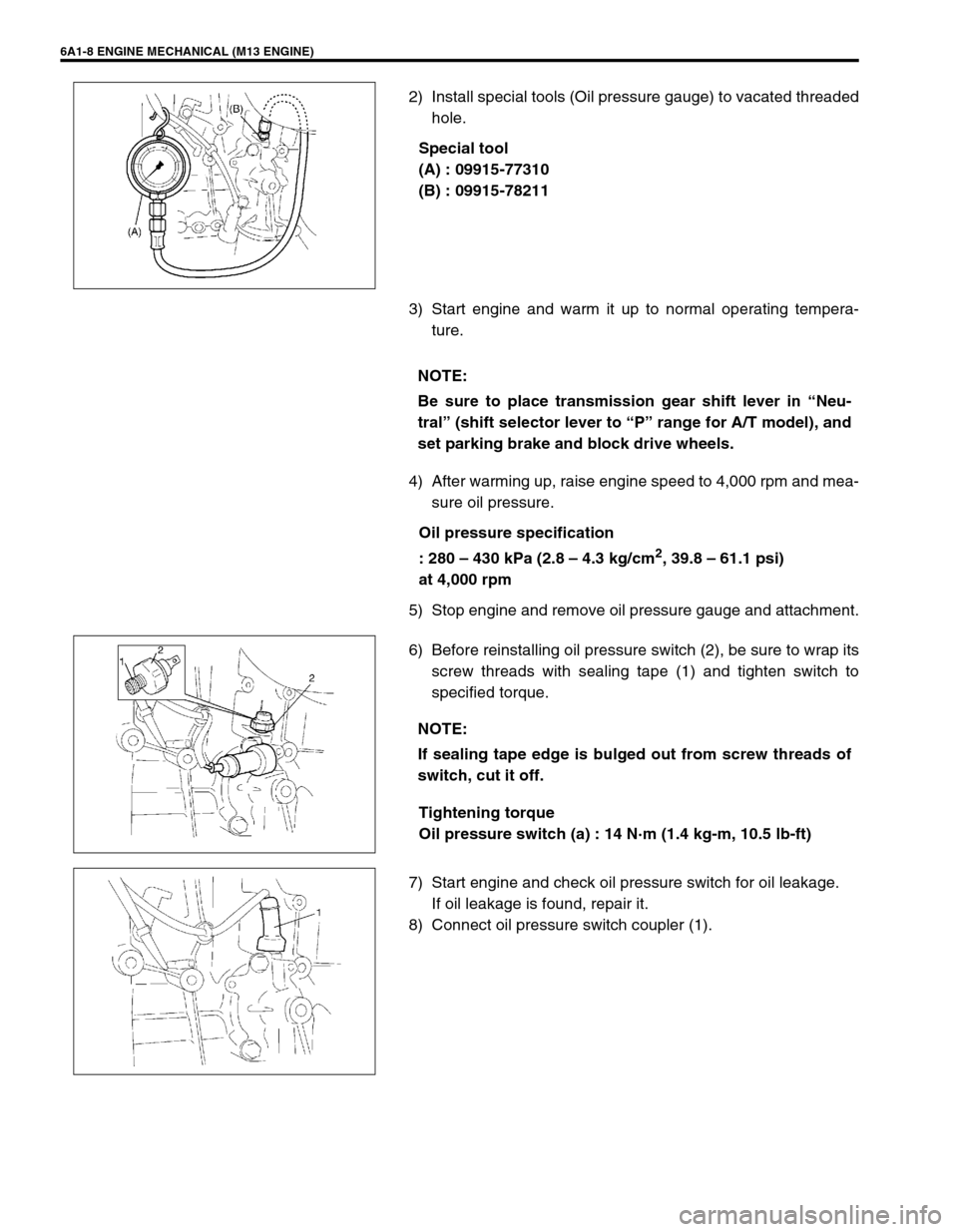
2) Install special tools (Oil pressure gauge) to vacated threaded
hole.
Special tool
(A) : 09915-77310
(B) : 09915-78211
3) Start engine and warm it up to normal operating tempera-
ture.
4) After warming up, raise engine speed to 4,000 rpm and mea-
sure oil pressure.
Oil pressure specification
: 280 – 430 kPa (2.8 – 4.3 kg/cm
2, 39.8 – 61.1 psi)
at 4,000 rpm
5) Stop engine and remove oil pressure gauge and attachment.
6) Before reinstalling oil pressure switch (2), be sure to wrap its
screw threads with sealing tape (1) and tighten switch to
specified torque.
Tightening torque
Oil pressure switch (a) : 14 N·m (1.4 kg-m, 10.5 lb-ft)
7) Start engine and check oil pressure switch for oil leakage.
If oil leakage is found, repair it.
8) Connect oil pressure switch coupler (1).
NOTE:
Be sure to place transmission gear shift lever in “Neu-
tral” (shift selector lever to “P” range for A/T model), and
set parking brake and block drive wheels.
NOTE:
If sealing tape edge is bulged out from screw threads of
switch, cut it off.
Page 566 of 698
ENGINE MECHANICAL (M13 ENGINE) 6A1-65
INSTALLATION
1) Apply engine oil to pistons, rings, cylinder walls, connecting
rod bearings and crankpins.
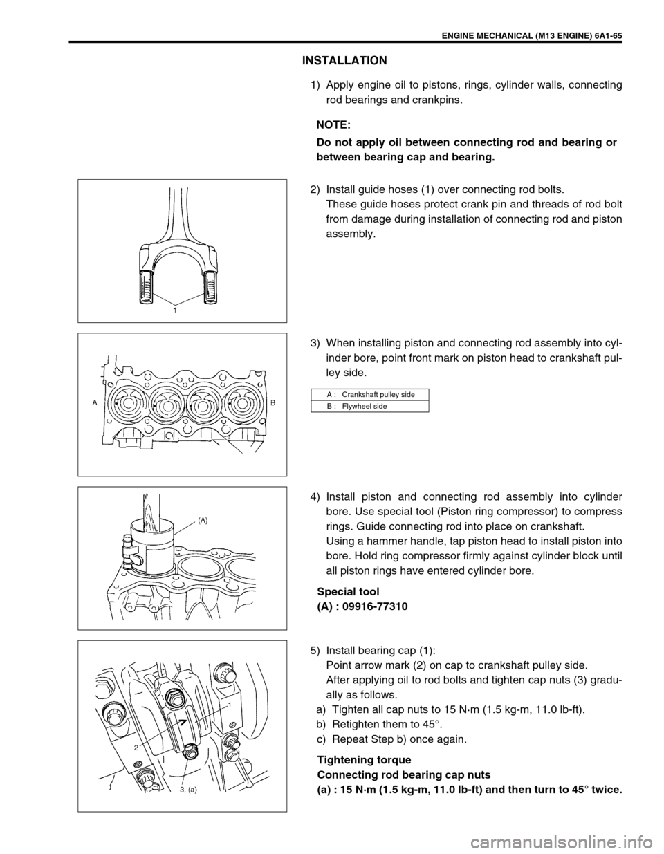
2) Install guide hoses (1) over connecting rod bolts.
These guide hoses protect crank pin and threads of rod bolt
from damage during installation of connecting rod and piston
assembly.
3) When installing piston and connecting rod assembly into cyl-
inder bore, point front mark on piston head to crankshaft pul-
ley side.
4) Install piston and connecting rod assembly into cylinder
bore. Use special tool (Piston ring compressor) to compress
rings. Guide connecting rod into place on crankshaft.
Using a hammer handle, tap piston head to install piston into
bore. Hold ring compressor firmly against cylinder block until
all piston rings have entered cylinder bore.
Special tool
(A) : 09916-77310
5) Install bearing cap (1):
Point arrow mark (2) on cap to crankshaft pulley side.
After applying oil to rod bolts and tighten cap nuts (3) gradu-
ally as follows.
a) Tighten all cap nuts to 15 N·m (1.5 kg-m, 11.0 lb-ft).
b) Retighten them to 45°.
c) Repeat Step b) once again.
Tightening torque
Connecting rod bearing cap nuts
(a) : 15 N·m (1.5 kg-m, 11.0 lb-ft) and then turn to 45° twice. NOTE:
Do not apply oil between connecting rod and bearing or
between bearing cap and bearing.
A : Crankshaft pulley side
B : Flywheel side
Page 575 of 698
6A1-74 ENGINE MECHANICAL (M13 ENGINE)
REMOVAL
1) Remove engine assembly from vehicle as previously out-
lined.
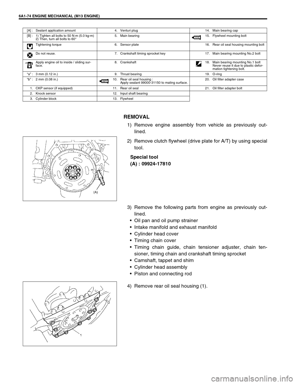
2) Remove clutch flywheel (drive plate for A/T) by using special
tool.
Special tool
(A) : 09924-17810
3) Remove the following parts from engine as previously out-
lined.
Oil pan and oil pump strainer
Intake manifold and exhaust manifold
Cylinder head cover
Timing chain cover
Timing chain guide, chain tensioner adjuster, chain ten-
sioner, timing chain and crankshaft timing sprocket
Camshaft, tappet and shim
Cylinder head assembly
Piston and connecting rod
4) Remove rear oil seal housing (1).
[A] : Sealant application amount 4. Venturi plug 14. Main bearing cap
[B] : 1) Tighten all bolts to 50 N·m (5.0 kg-m)
2) Then, turn all bolts to 60°5. Main bearing 15. Flywheel mounting bolt
Tightening torque 6. Sensor plate 16. Rear oil seal housing mounting bolt
Do not reuse. 7. Crankshaft timing sprocket key 17. Main bearing mounting No.2 bolt
Apply engine oil to inside / sliding sur-
face.8. Crankshaft
18. Main bearing mounting No.1 bolt
Never reuse it due to plastic defor-
mation tightening bolt.
“a” : 3 mm (0.12 in.) 9. Thrust bearing 19. O-ring
“b” : 2 mm (0.08 in.) 10. Rear oil seal housing :
Apply sealant 99000-31150 to mating surface.20. Oil filter adapter case
1. CKP sensor (if equipped) 11. Rear oil seal 21. Oil filter adapter bolt
2. Knock sensor 12. Input shaft bearing
3. Cylinder block 13. Flywheel
Page 582 of 698
ENGINE MECHANICAL (M13 ENGINE) 6A1-81
Rear Oil Seal
Carefully inspect oil seal (1) for wear or damage.
If its lip is worn or damaged, replace it.
For oil seal installation, press-fit rear oil seal (1) to oil seal housing
(2) by using special tool as shown in the figure.
Special tool
(A) : 09911-97820
Drive in dimension
“a” : 3 mm (0.12 in.)
Flywheel
If ring gear is damaged, cracked or worn, replace flywheel.
If the surface contacting clutch disc is damaged, or exces-
sively worn, replace flywheel.
Check flywheel for face runout with a dial gauge.
If runout exceeds its limit, replace flywheel.
Flywheel on runout
Limit : 0.2 mm (0.0079 in.)
Sensor plate
Check sensor plate for crack or damage. If malcondition is
found, replace it.
Page 586 of 698
ENGINE MECHANICAL (M13 ENGINE) 6A1-85
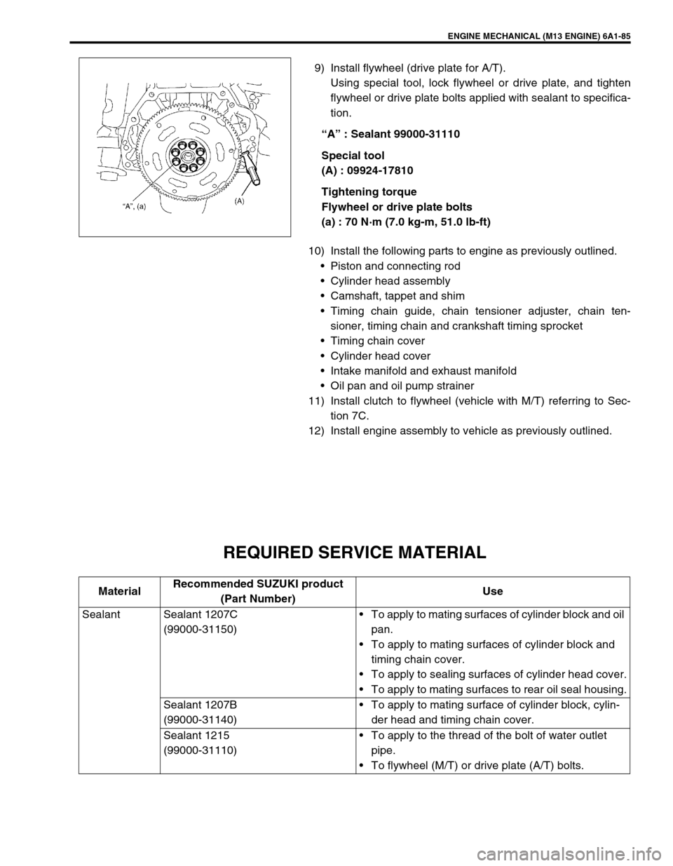
9) Install flywheel (drive plate for A/T).
Using special tool, lock flywheel or drive plate, and tighten
flywheel or drive plate bolts applied with sealant to specifica-
tion.
“A” : Sealant 99000-31110
Special tool
(A) : 09924-17810
Tightening torque
Flywheel or drive plate bolts
(a) : 70 N·m (7.0 kg-m, 51.0 lb-ft)
10) Install the following parts to engine as previously outlined.
Piston and connecting rod
Cylinder head assembly
Camshaft, tappet and shim
Timing chain guide, chain tensioner adjuster, chain ten-
sioner, timing chain and crankshaft timing sprocket
Timing chain cover
Cylinder head cover
Intake manifold and exhaust manifold
Oil pan and oil pump strainer
11) Install clutch to flywheel (vehicle with M/T) referring to Sec-
tion 7C.
12) Install engine assembly to vehicle as previously outlined.
REQUIRED SERVICE MATERIAL
MaterialRecommended SUZUKI product
(Part Number)Use
Sealant Sealant 1207C
(99000-31150)To apply to mating surfaces of cylinder block and oil
pan.
To apply to mating surfaces of cylinder block and
timing chain cover.
To apply to sealing surfaces of cylinder head cover.
To apply to mating surfaces to rear oil seal housing.
Sealant 1207B
(99000-31140)To apply to mating surface of cylinder block, cylin-
der head and timing chain cover.
Sealant 1215
(99000-31110)To apply to the thread of the bolt of water outlet
pipe.
To flywheel (M/T) or drive plate (A/T) bolts.
Page 587 of 698
6A1-86 ENGINE MECHANICAL (M13 ENGINE)
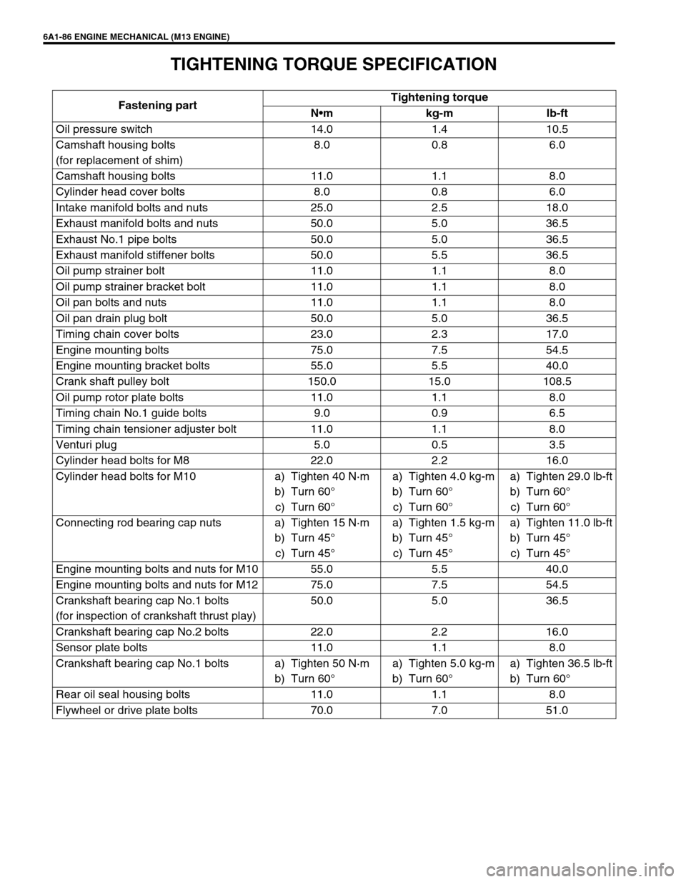
TIGHTENING TORQUE SPECIFICATION
Fastening partTightening torque
Nm kg-m lb-ft
Oil pressure switch 14.0 1.4 10.5
Camshaft housing bolts
(for replacement of shim)8.0 0.8 6.0
Camshaft housing bolts 11.0 1.1 8.0
Cylinder head cover bolts 8.0 0.8 6.0
Intake manifold bolts and nuts 25.0 2.5 18.0
Exhaust manifold bolts and nuts 50.0 5.0 36.5
Exhaust No.1 pipe bolts 50.0 5.0 36.5
Exhaust manifold stiffener bolts 50.0 5.5 36.5
Oil pump strainer bolt 11.0 1.1 8.0
Oil pump strainer bracket bolt 11.0 1.1 8.0
Oil pan bolts and nuts 11.0 1.1 8.0
Oil pan drain plug bolt 50.0 5.0 36.5
Timing chain cover bolts 23.0 2.3 17.0
Engine mounting bolts 75.0 7.5 54.5
Engine mounting bracket bolts 55.0 5.5 40.0
Crank shaft pulley bolt 150.0 15.0 108.5
Oil pump rotor plate bolts 11.0 1.1 8.0
Timing chain No.1 guide bolts 9.0 0.9 6.5
Timing chain tensioner adjuster bolt 11.0 1.1 8.0
Venturi plug 5.0 0.5 3.5
Cylinder head bolts for M8 22.0 2.2 16.0
Cylinder head bolts for M10 a) Tighten 40 N·m
b) Turn 60°
c) Turn 60°a) Tighten 4.0 kg-m
b) Turn 60°
c) Turn 60°a) Tighten 29.0 lb-ft
b) Turn 60°
c) Turn 60°
Connecting rod bearing cap nuts a) Tighten 15 N·m
b) Turn 45°
c) Turn 45°a) Tighten 1.5 kg-m
b) Turn 45°
c) Turn 45°a) Tighten 11.0 lb-ft
b) Turn 45°
c) Turn 45°
Engine mounting bolts and nuts for M10 55.0 5.5 40.0
Engine mounting bolts and nuts for M12 75.0 7.5 54.5
Crankshaft bearing cap No.1 bolts
(for inspection of crankshaft thrust play)50.0 5.0 36.5
Crankshaft bearing cap No.2 bolts 22.0 2.2 16.0
Sensor plate bolts 11.0 1.1 8.0
Crankshaft bearing cap No.1 bolts a) Tighten 50 N·m
b) Turn 60°a) Tighten 5.0 kg-m
b) Turn 60°a) Tighten 36.5 lb-ft
b) Turn 60°
Rear oil seal housing bolts 11.0 1.1 8.0
Flywheel or drive plate bolts 70.0 7.0 51.0
Page 589 of 698
6A1-88 ENGINE MECHANICAL (M13 ENGINE)
09916-37810 09916-38210 09916-44910 09916-46020
Reamer (6 mm) Reamer (11 mm) Valve guide remover Valve guide remover
09916-56011 09916-57350 09916-58210 09916-67020
Valve guide installer
attachmentValve guide installer han-
dleValve guide installer han-
dleTappet holder
09916-77310 09916-84511 09917-98221 09917-88240
Piston ring compressor Forceps Camshaft lock holder Valve guide installer
09917-88250 09917-98221 09924-17810
Valve guide installer Valve stem seal installer Flywheel holder