Page 364 of 698

ANTILOCK BRAKE SYSTEM (ABS) 5E-39
Reference
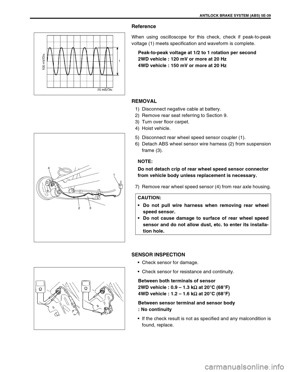
When using oscilloscope for this check, check if peak-to-peak
voltage (1) meets specification and waveform is complete.
Peak-to-peak voltage at 1/2 to 1 rotation per second
2WD vehicle : 120 mV or more at 20 Hz
4WD vehicle : 150 mV or more at 20 Hz
REMOVAL
1) Disconnect negative cable at battery.
2) Remove rear seat referring to Section 9.
3) Turn over floor carpet.
4) Hoist vehicle.
5) Disconnect rear wheel speed sensor coupler (1).
6) Detach ABS wheel sensor wire harness (2) from suspension
frame (3).
7) Remove rear wheel speed sensor (4) from rear axle housing.
SENSOR INSPECTION
Check sensor for damage.
Check sensor for resistance and continuity.
Between both terminals of sensor
2WD vehicle : 0.9 – 1.3 k
Ω
ΩΩ Ω at 20°C (68°F)
4WD vehicle : 1.2 – 1.6 k
Ω
ΩΩ Ω at 20°C (68°F)
Between sensor terminal and sensor body
: No continuity
If the check result is not as specified and any malcondition is
found, replace.
NOTE:
Do not detach crip of rear wheel speed sensor connector
from vehicle body unless replacement is necessary.
CAUTION:
Do not pull wire harness when removing rear wheel
speed sensor.
Do not cause damage to surface of rear wheel speed
sensor and do not allow dust, etc. to enter its installa-
tion hole.
4
231
Page 365 of 698
5E-40 ANTILOCK BRAKE SYSTEM (ABS)
SENSOR ROTOR INSPECTION
Check rotor serration (teeth) for being missing, damaged or
deformed.
Turn wheel and check if rotor rotation is free from eccentric-
ity and looseness.
Check that no foreign material is attached.
If any faulty is found, repair or replace.
INSTALLATION
Reverse removal procedure for installation noting the following.
Check that no foreign material is attached to sensor (1) and
ring.
Be sure to install wheel speed sensor and its bolt at the cor-
rect (upper) position as shown in figure.
Tighten sensor bolt to specified torque.
Tightening torque
Sensor bolt (a) : 10 N·m (1.0 kg-m, 7.5 lb-ft)
Check that there is no clearance between sensor and rear
axle shaft.
[A] : For 2WD
[B] : For 4WD
[B] [A]
1
CAUTION:
Do not pull or twist wire harness more than necessary
when installing rear wheel speed sensor.
Page 366 of 698
ANTILOCK BRAKE SYSTEM (ABS) 5E-41
REAR WHEEL SPEED SENSOR RING (FOR
2WD VEHICLE)
REMOVAL
1) Remove rear wheel sensor from rear axle housing.
2) Remove brake drum referring to Section 5.
3) Remove sensor ring (1) from brake drum (2) using special
tools.
Special tool
(A) : 09913-75520
(B) : 09913-65135
INSTALLATION
1) Install new sensor ring (1) to brake drum (2) using special
tool and hydraulic press (3).
Special tool
(A) : 09913-75840
2) Install brake drum. Refer to Section 5.
3) Install rear wheel speed sensor (1) to rear axle housing.
Tightening torque
Rear wheel speed sensor (a) : 10 N·m (1.0 kg-m, 7.5 lb-ft) CAUTION:
Pull out sensor ring from brake drum gradually and
evenly. Attempt to pull it out partially may cause it to be
deformed.
NOTE:
Do not reuse (reinstall) removed sensor ring.
1
(a)
Page 367 of 698
5E-42 ANTILOCK BRAKE SYSTEM (ABS)
REAR WHEEL SPEED SENSOR RING (FOR
4WD VEHICLE)
REMOVAL
1) Remove rear axle shaft referring to Section 3E.
2) Remove rear wheel sensor ring from axle shaft by using spe-
cial tools.
Special tool
(A) : 09927-18411
(B) : 09921-57810
INSTALLATION
1) Install new wheel sensor ring (1) by using hydraulic press
(2).
2) Install rear axle shaft referring to Section 3E.
3) Install wheel speed sensor to rear axle housing.
Tightening torque
Wheel sensor ring bolt : 10 N·m (1.0 kg-m, 7.5 lb-ft)
NOTE:
Do not reuse (reinstall) removed sensor ring.
Do not damage to retainer ring when press fitting
wheel sensor ring.
1 2
Page 373 of 698

6-4 ENGINE GENERAL INFORMATION AND DIAGNOSIS
GENERAL INFORMATION
STATEMENT ON CLEANLINESS AND CARE
An automobile engine is a combination of many machined, honed, polished and lapped surfaces with tolerances
that are measured in the thousands of an millimeter (ten thousands of an inch).
Accordingly, when any internal engine parts are serviced, care and cleanliness are important.
Throughout this section, it should be understood that proper cleaning and protection of machined surfaces and
friction areas is part of the repair procedure. This is considered standard shop practice even if not specifically
stated.
A liberal coating of engine oil should be applied to friction areas during assembly to protect and lubricate the
surfaces on initial operation.
Whenever valve train components, pistons, piston rings, connecting rods, rod bearings, and crankshaft jour-
nal bearings are removed for service, they should be retained in order.
At the time of installation, they should be installed in the same locations and with the same mating surfaces
as when removed.
Battery cables should be disconnected before any major work is performed on the engine.
Failure to disconnect cables may result in damage to wire harness or other electrical parts.
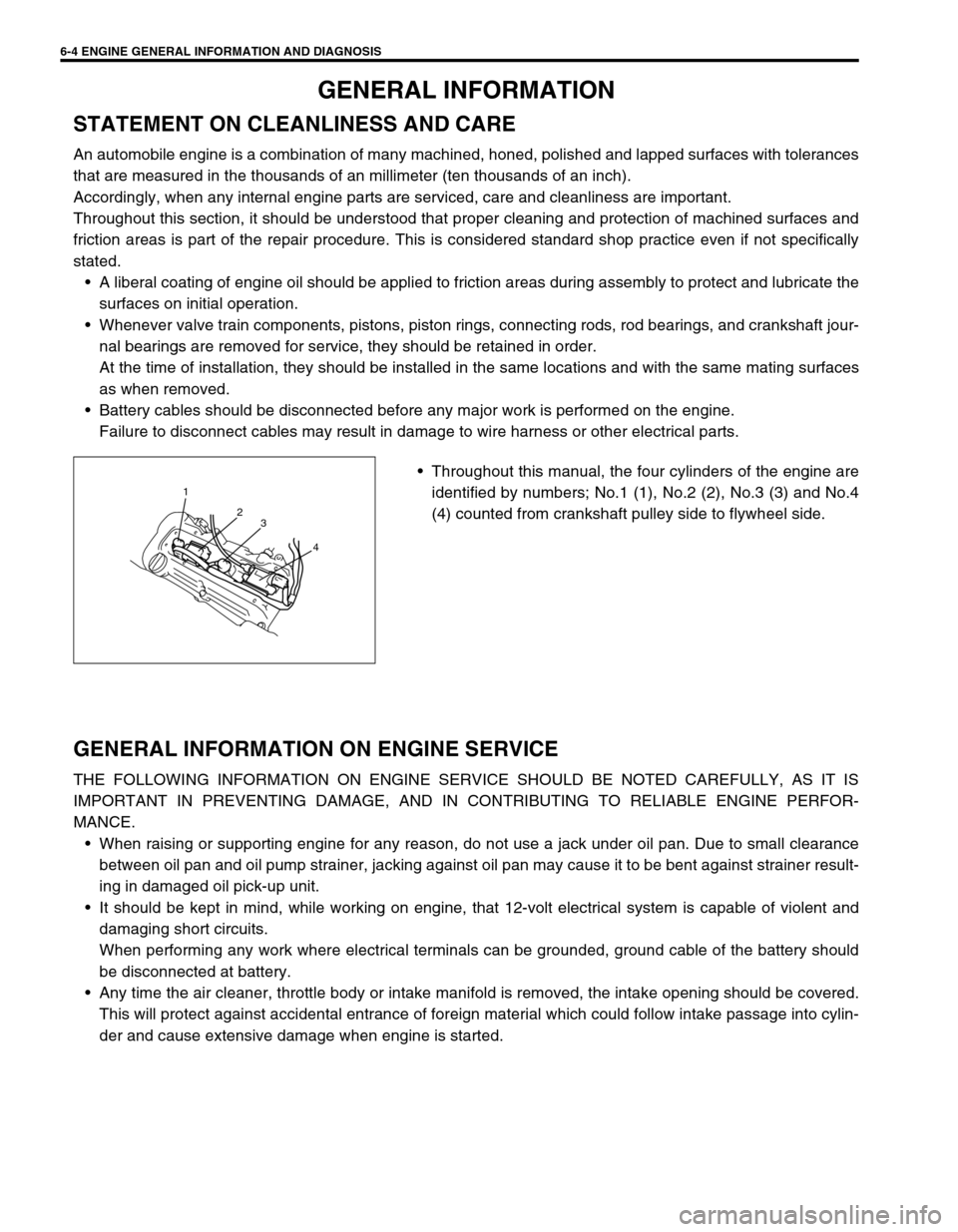
Throughout this manual, the four cylinders of the engine are
identified by numbers; No.1 (1), No.2 (2), No.3 (3) and No.4
(4) counted from crankshaft pulley side to flywheel side.
GENERAL INFORMATION ON ENGINE SERVICE
THE FOLLOWING INFORMATION ON ENGINE SERVICE SHOULD BE NOTED CAREFULLY, AS IT IS
IMPORTANT IN PREVENTING DAMAGE, AND IN CONTRIBUTING TO RELIABLE ENGINE PERFOR-
MANCE.
When raising or supporting engine for any reason, do not use a jack under oil pan. Due to small clearance
between oil pan and oil pump strainer, jacking against oil pan may cause it to be bent against strainer result-
ing in damaged oil pick-up unit.
It should be kept in mind, while working on engine, that 12-volt electrical system is capable of violent and
damaging short circuits.
When performing any work where electrical terminals can be grounded, ground cable of the battery should
be disconnected at battery.
Any time the air cleaner, throttle body or intake manifold is removed, the intake opening should be covered.
This will protect against accidental entrance of foreign material which could follow intake passage into cylin-
der and cause extensive damage when engine is started.
1
2
3
4
Page 375 of 698

6-6 ENGINE GENERAL INFORMATION AND DIAGNOSIS
FUEL PRESSURE RELIEF PROCEDURE
After making sure that engine is cold, release fuel pressure as fol-
lows.
1) Place transmission gear shift lever in “Neutral” (Shift selector
lever to “P” range for A/T model), set parking brake, and
block drive wheels.
2) Remove relay box cover.
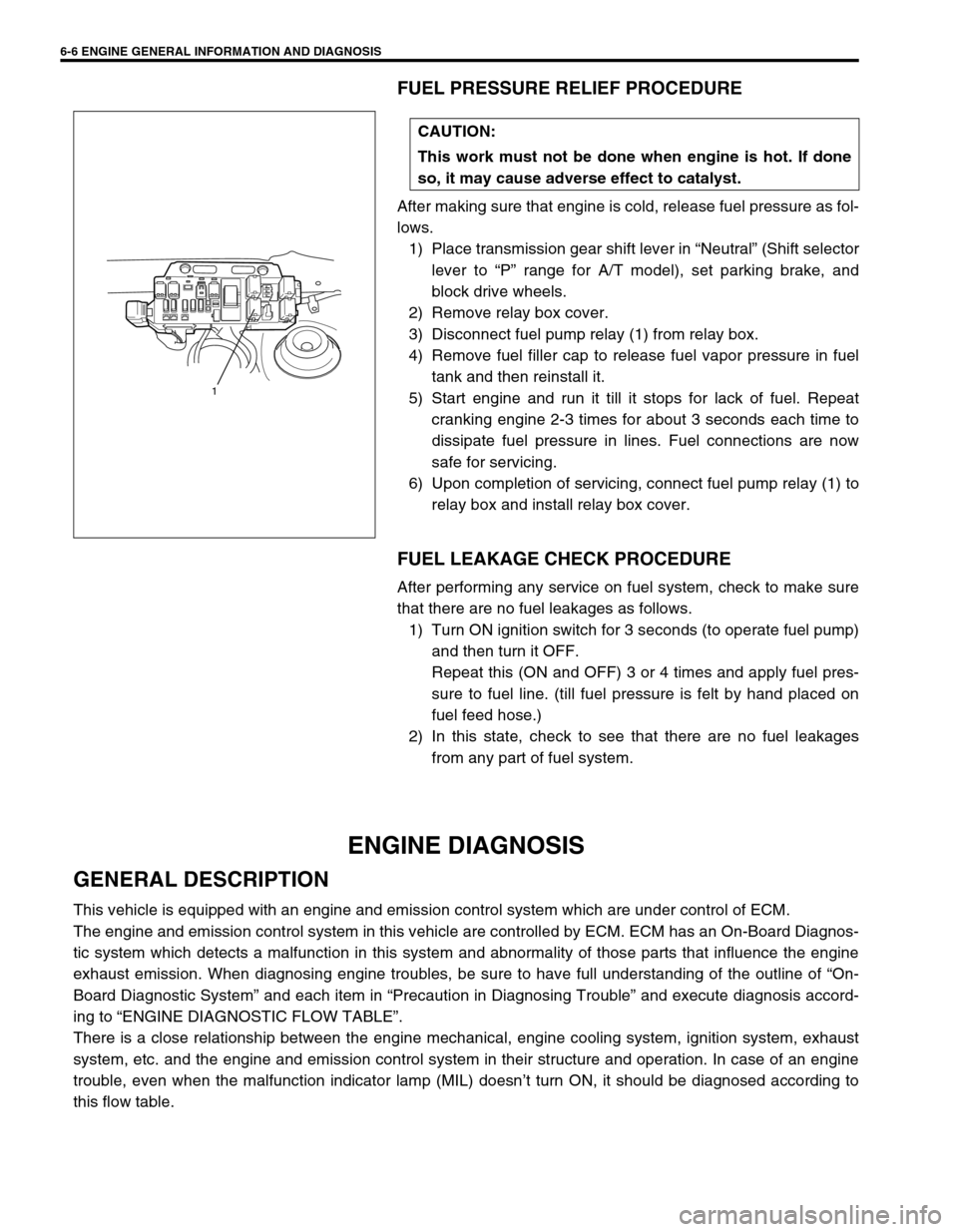
3) Disconnect fuel pump relay (1) from relay box.
4) Remove fuel filler cap to release fuel vapor pressure in fuel
tank and then reinstall it.
5) Start engine and run it till it stops for lack of fuel. Repeat
cranking engine 2-3 times for about 3 seconds each time to
dissipate fuel pressure in lines. Fuel connections are now
safe for servicing.
6) Upon completion of servicing, connect fuel pump relay (1) to
relay box and install relay box cover.
FUEL LEAKAGE CHECK PROCEDURE
After performing any service on fuel system, check to make sure
that there are no fuel leakages as follows.
1) Turn ON ignition switch for 3 seconds (to operate fuel pump)
and then turn it OFF.
Repeat this (ON and OFF) 3 or 4 times and apply fuel pres-
sure to fuel line. (till fuel pressure is felt by hand placed on
fuel feed hose.)
2) In this state, check to see that there are no fuel leakages
from any part of fuel system.
ENGINE DIAGNOSIS
GENERAL DESCRIPTION
This vehicle is equipped with an engine and emission control system which are under control of ECM.
The engine and emission control system in this vehicle are controlled by ECM. ECM has an On-Board Diagnos-
tic system which detects a malfunction in this system and abnormality of those parts that influence the engine
exhaust emission. When diagnosing engine troubles, be sure to have full understanding of the outline of “On-
Board Diagnostic System” and each item in “Precaution in Diagnosing Trouble” and execute diagnosis accord-
ing to “ENGINE DIAGNOSTIC FLOW TABLE”.
There is a close relationship between the engine mechanical, engine cooling system, ignition system, exhaust
system, etc. and the engine and emission control system in their structure and operation. In case of an engine
trouble, even when the malfunction indicator lamp (MIL) doesn’t turn ON, it should be diagnosed according to
this flow table.CAUTION:
This work must not be done when engine is hot. If done
so, it may cause adverse effect to catalyst.
1
Page 475 of 698

6-106 ENGINE GENERAL INFORMATION AND DIAGNOSIS
INSPECTION
Fig. 1 for Step 3Step Action Yes No
1Was “ENGINE DIAG. FLOW TABLE” per-
formed?Go to Step 2. Go to “ENGINE DIAG.
FLOW TABLE”.
2 Is SUZUKI scan tool available? Go to Step 3. Go to Step 4.
3 Check Idle Air Control System.
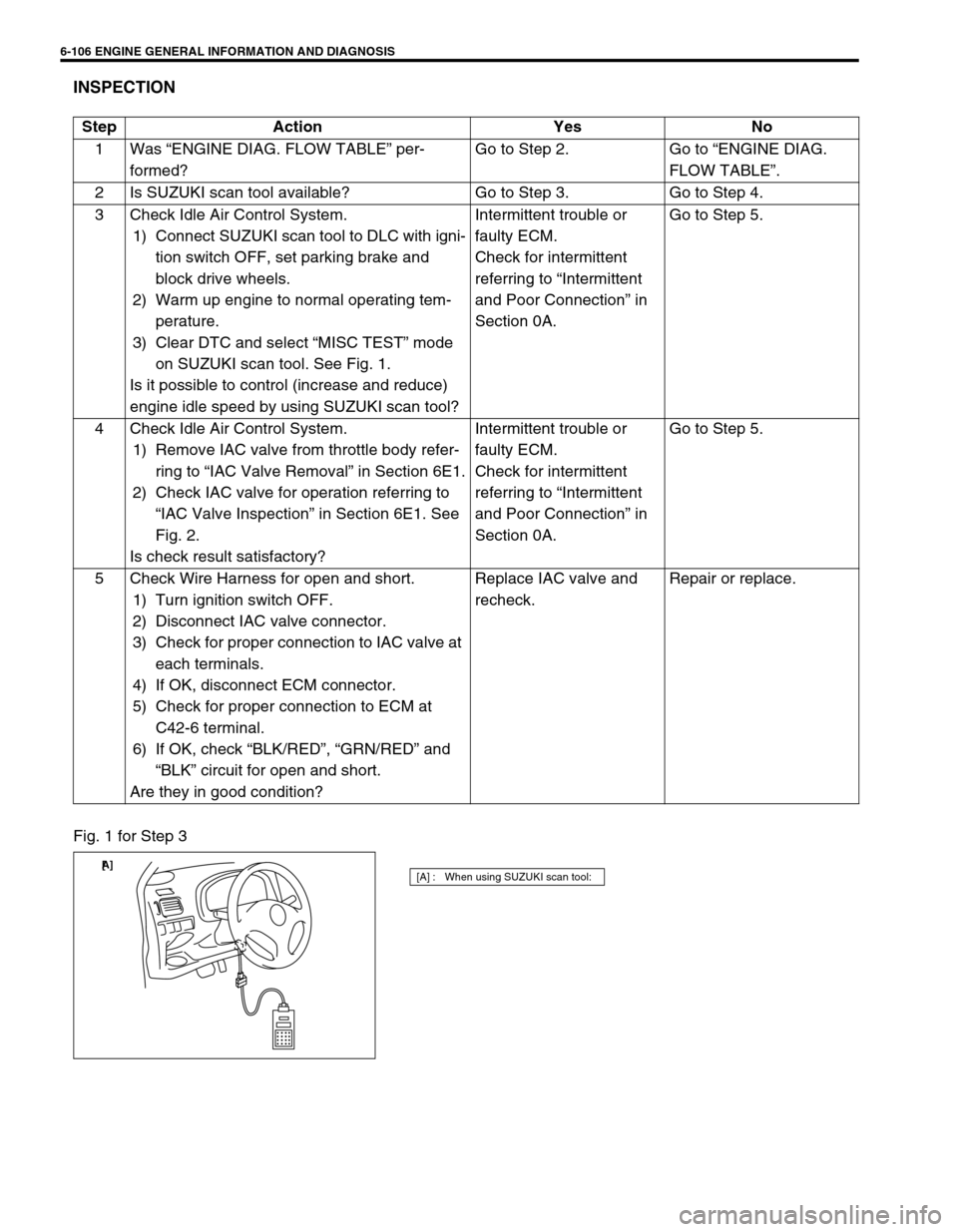
1) Connect SUZUKI scan tool to DLC with igni-
tion switch OFF, set parking brake and
block drive wheels.
2) Warm up engine to normal operating tem-
perature.
3) Clear DTC and select “MISC TEST” mode
on SUZUKI scan tool. See Fig. 1.
Is it possible to control (increase and reduce)
engine idle speed by using SUZUKI scan tool? Intermittent trouble or
faulty ECM.
Check for intermittent
referring to “Intermittent
and Poor Connection” in
Section 0A.Go to Step 5.
4 Check Idle Air Control System.
1) Remove IAC valve from throttle body refer-
ring to “IAC Valve Removal” in Section 6E1.
2) Check IAC valve for operation referring to
“IAC Valve Inspection” in Section 6E1. See
Fig. 2.
Is check result satisfactory?Intermittent trouble or
faulty ECM.
Check for intermittent
referring to “Intermittent
and Poor Connection” in
Section 0A.Go to Step 5.
5 Check Wire Harness for open and short.
1) Turn ignition switch OFF.
2) Disconnect IAC valve connector.
3) Check for proper connection to IAC valve at
each terminals.
4) If OK, disconnect ECM connector.
5) Check for proper connection to ECM at
C42-6 terminal.
6) If OK, check “BLK/RED”, “GRN/RED” and
“BLK” circuit for open and short.
Are they in good condition?Replace IAC valve and
recheck.Repair or replace.
[A] : When using SUZUKI scan tool:[ A]
Page 505 of 698
6A1-4 ENGINE MECHANICAL (M13 ENGINE)
DIAGNOSIS
DIAGNOSIS TABLE
Refer to “ENGINE MECHANICAL DIAGNOSIS TABLE” in Sec-
tion 6.
COMPRESSION CHECK
Check compression pressure on all 4 cylinders as follows:
1) Warm up engine to normal operating temperature.
2) Stop engine after warming up.
3) Remove air cleaner assembly (1), resonator (2) and hoses.
Refer to “AIR CLEANER ASSEMBLY AND RESONATOR”.
4) Remove cylinder head upper cover (1).
5) Disconnect ignition coil couplers (1).
6) Remove ignition coil assemblies (2) with high-tension cord
(3).
7) Remove all spark plugs.
8) Disconnect fuel injector wires (4) at the coupler.NOTE:
After warming up engine, place transmission gear shift
lever in “Neutral” (shift selector lever to “P” range for A/T
model), and set parking brake and block drive wheels.