Page 41 of 698
0B-12 MAINTENANCE AND LUBRICATION
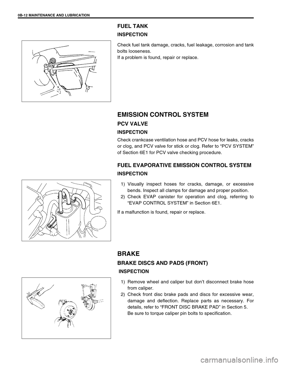
FUEL TANK
INSPECTION
Check fuel tank damage, cracks, fuel leakage, corrosion and tank
bolts looseness.
If a problem is found, repair or replace.
EMISSION CONTROL SYSTEM
PCV VALVE
INSPECTION
Check crankcase ventilation hose and PCV hose for leaks, cracks
or clog, and PCV valve for stick or clog. Refer to “PCV SYSTEM”
of Section 6E1 for PCV valve checking procedure.
FUEL EVAPORATIVE EMISSION CONTROL SYSTEM
INSPECTION
1) Visually inspect hoses for cracks, damage, or excessive
bends. Inspect all clamps for damage and proper position.
2) Check EVAP canister for operation and clog, referring to
“EVAP CONTROL SYSTEM” in Section 6E1.
If a malfunction is found, repair or replace.
BRAKE
BRAKE DISCS AND PADS (FRONT)
INSPECTION
1) Remove wheel and caliper but don’t disconnect brake hose
from caliper.
2) Check front disc brake pads and discs for excessive wear,
damage and deflection. Replace parts as necessary. For
details, refer to “FRONT DISC BRAKE PAD” in Section 5.
Be sure to torque caliper pin bolts to specification.
Page 45 of 698
0B-16 MAINTENANCE AND LUBRICATION
3) Check steering linkage for looseness and damage. Repair or
replace defective parts, if any.
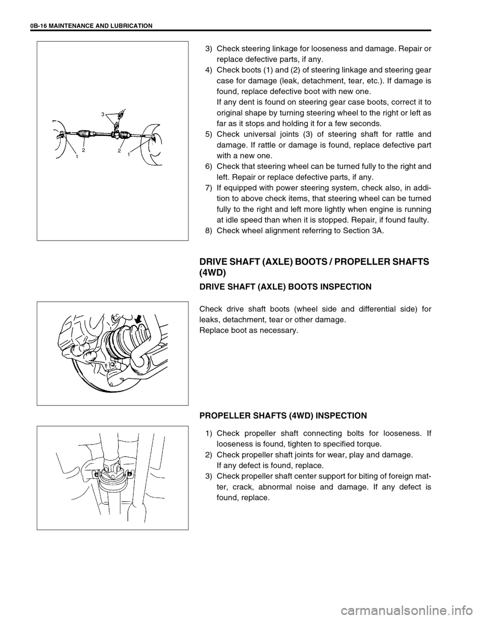
4) Check boots (1) and (2) of steering linkage and steering gear
case for damage (leak, detachment, tear, etc.). If damage is
found, replace defective boot with new one.
If any dent is found on steering gear case boots, correct it to
original shape by turning steering wheel to the right or left as
far as it stops and holding it for a few seconds.
5) Check universal joints (3) of steering shaft for rattle and
damage. If rattle or damage is found, replace defective part
with a new one.
6) Check that steering wheel can be turned fully to the right and
left. Repair or replace defective parts, if any.
7) If equipped with power steering system, check also, in addi-
tion to above check items, that steering wheel can be turned
fully to the right and left more lightly when engine is running
at idle speed than when it is stopped. Repair, if found faulty.
8) Check wheel alignment referring to Section 3A.
DRIVE SHAFT (AXLE) BOOTS / PROPELLER SHAFTS
(4WD)
DRIVE SHAFT (AXLE) BOOTS INSPECTION
Check drive shaft boots (wheel side and differential side) for
leaks, detachment, tear or other damage.
Replace boot as necessary.
PROPELLER SHAFTS (4WD) INSPECTION
1) Check propeller shaft connecting bolts for looseness. If
looseness is found, tighten to specified torque.
2) Check propeller shaft joints for wear, play and damage.
If any defect is found, replace.
3) Check propeller shaft center support for biting of foreign mat-
ter, crack, abnormal noise and damage. If any defect is
found, replace.
Page 46 of 698
MAINTENANCE AND LUBRICATION 0B-17
MANUAL TRANSMISSION OIL
INSPECTION
1) Inspect transmission case for evidence of oil leakage.
Repair leaky point if any.
2) Make sure that vehicle is placed level for oil level check.
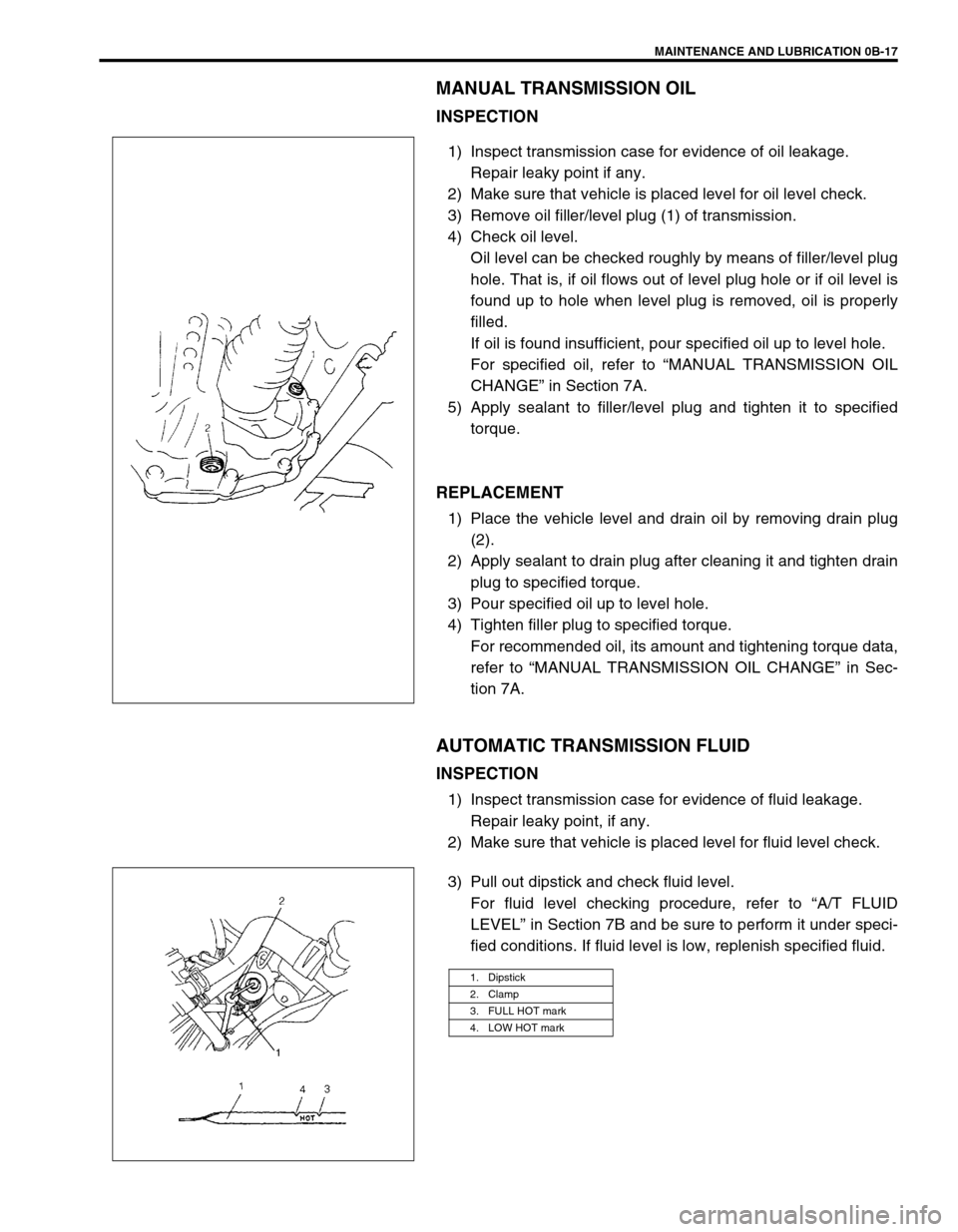
3) Remove oil filler/level plug (1) of transmission.
4) Check oil level.
Oil level can be checked roughly by means of filler/level plug
hole. That is, if oil flows out of level plug hole or if oil level is
found up to hole when level plug is removed, oil is properly
filled.
If oil is found insufficient, pour specified oil up to level hole.
For specified oil, refer to “MANUAL TRANSMISSION OIL
CHANGE” in Section 7A.
5) Apply sealant to filler/level plug and tighten it to specified
torque.
REPLACEMENT
1) Place the vehicle level and drain oil by removing drain plug
(2).
2) Apply sealant to drain plug after cleaning it and tighten drain
plug to specified torque.
3) Pour specified oil up to level hole.
4) Tighten filler plug to specified torque.
For recommended oil, its amount and tightening torque data,
refer to “MANUAL TRANSMISSION OIL CHANGE” in Sec-
tion 7A.
AUTOMATIC TRANSMISSION FLUID
INSPECTION
1) Inspect transmission case for evidence of fluid leakage.
Repair leaky point, if any.
2) Make sure that vehicle is placed level for fluid level check.
3) Pull out dipstick and check fluid level.
For fluid level checking procedure, refer to “A/T FLUID
LEVEL” in Section 7B and be sure to perform it under speci-
fied conditions. If fluid level is low, replenish specified fluid.
1. Dipstick
2. Clamp
3. FULL HOT mark
4. LOW HOT mark
Page 47 of 698
0B-18 MAINTENANCE AND LUBRICATION
REPLACEMENT
1) Inspect transmission case for evidence of fluid leakage.
Repair leaky point, if any.
2) Make sure that vehicle is placed level for fluid level check.
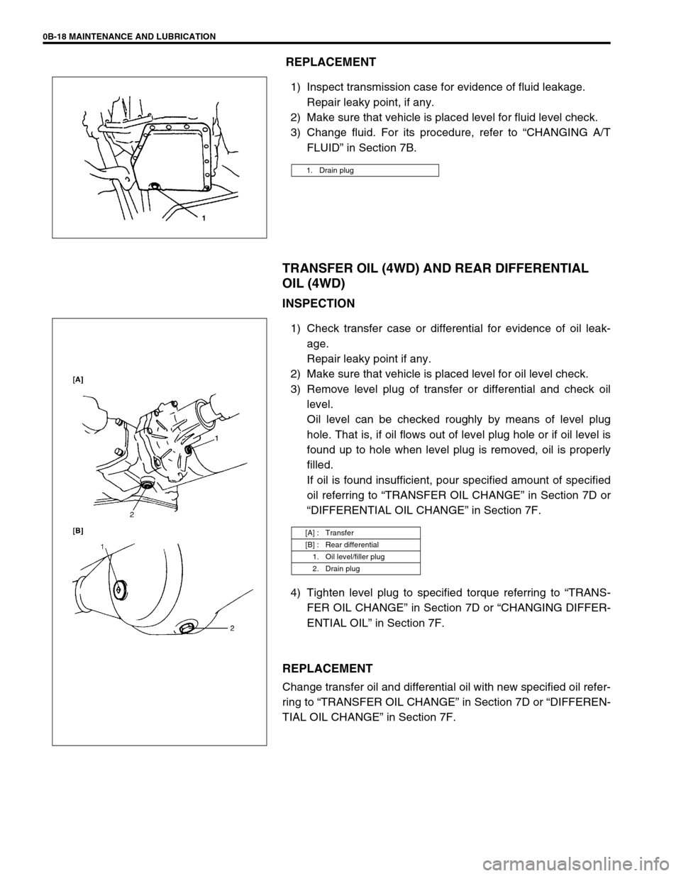
3) Change fluid. For its procedure, refer to “CHANGING A/T
FLUID” in Section 7B.
TRANSFER OIL (4WD) AND REAR DIFFERENTIAL
OIL (4WD)
INSPECTION
1) Check transfer case or differential for evidence of oil leak-
age.
Repair leaky point if any.
2) Make sure that vehicle is placed level for oil level check.
3) Remove level plug of transfer or differential and check oil
level.
Oil level can be checked roughly by means of level plug
hole. That is, if oil flows out of level plug hole or if oil level is
found up to hole when level plug is removed, oil is properly
filled.
If oil is found insufficient, pour specified amount of specified
oil referring to “TRANSFER OIL CHANGE” in Section 7D or
“DIFFERENTIAL OIL CHANGE” in Section 7F.
4) Tighten level plug to specified torque referring to “TRANS-
FER OIL CHANGE” in Section 7D or “CHANGING DIFFER-
ENTIAL OIL” in Section 7F.
REPLACEMENT
Change transfer oil and differential oil with new specified oil refer-
ring to “TRANSFER OIL CHANGE” in Section 7D or “DIFFEREN-
TIAL OIL CHANGE” in Section 7F.
1. Drain plug
[A] : Transfer
[B] : Rear differential
1. Oil level/filler plug
2. Drain plug
Page 92 of 698
AIR CONDITIONING (OPTIONAL) 1B-27
ON-VEHICLE SERVICE
SERVICE PRECAUTION
When servicing air conditioning system, note the following instructions.
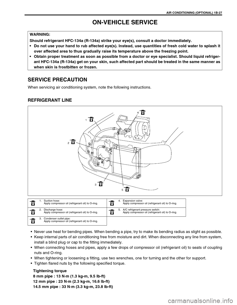
REFRIGERANT LINE
Never use heat for bending pipes. When bending a pipe, try to make its bending radius as slight as possible.
Keep internal parts of air conditioning free from moisture and dirt. When disconnecting any line from system,
install a blind plug or cap to the fitting immediately.
When connecting hoses and pipes, apply a few drops of compressor oil (refrigerant oil) to seats of coupling
nuts and O-ring.
When tightening or loosening a fitting, use two wrenches, one for turning and the other for support.
Tighten flared nuts by the following specified torque.
Tightening torque
8 mm pipe : 13 N·m (1.3 kg-m, 9.5 lb-ft)
12 mm pipe : 23 N·m (2.3 kg-m, 16.6 lb-ft)
14.5 mm pipe : 33 N·m (3.3 kg-m, 23.8 lb-ft) WARNING:
Should refrigerant HFC-134a (R-134a) strike your eye(s), consult a doctor immediately.
Do not use your hand to rub affected eye(s). Instead, use quantities of fresh cold water to splash it
over affected area to thus gradually raise its temperature above the freezing point.
Obtain proper treatment as soon as possible from a doctor or eye specialist. Should liquid refriger-
ant HFC-134a (R-134a) get on your skin, such affected part should be treated in the same manner as
when skin is frostbitten or frozen.
1. Suction hose:
Apply compressor oil (refrigerant oil) to O-ring.4. Expansion valve:
Apply compressor oil (refrigerant oil) to O-ring.
2. Discharge hose:
Apply compressor oil (refrigerant oil) to O-ring.5. A/C refrigerant pressure switch:
Apply compressor oil (refrigerant oil) to O-ring.
3. Condenser outlet pipe:
Apply compressor oil (refrigerant oil) to O-ring.
Page 96 of 698
AIR CONDITIONING (OPTIONAL) 1B-31
Tighten receiver/dryer cap to specified torque
Tightening torque
Receiver / dryer cap : 13 N·m (1.3 kg-m, 9.5 lb-ft)
Replenish specified amount of compressor oil to compressor
suction side by referring to “REPLENISHING COMPRES-
SOR OIL” in this section.
RADIATOR/CONDENSER COOLING FAN
MOTOR
REMOVAL AND INSTALLATION
For details, refer to “RADIATOR” in Section 6B.
INSPECTION
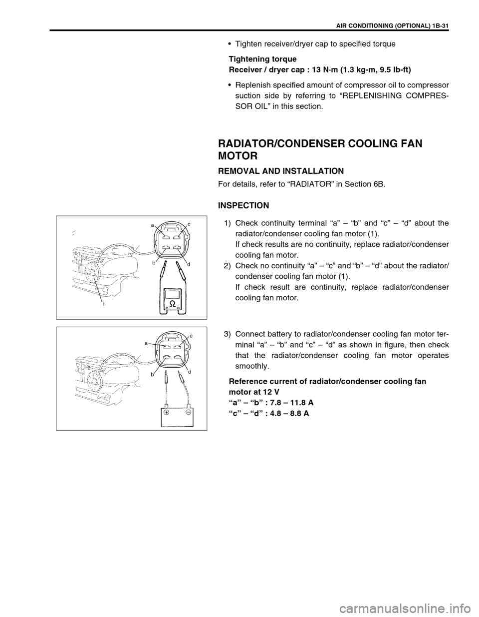
1) Check continuity terminal “a” – “b” and “c” – “d” about the
radiator/condenser cooling fan motor (1).
If check results are no continuity, replace radiator/condenser
cooling fan motor.
2) Check no continuity “a” – “c” and “b” – “d” about the radiator/
condenser cooling fan motor (1).
If check result are continuity, replace radiator/condenser
cooling fan motor.
3) Connect battery to radiator/condenser cooling fan motor ter-
minal “a” – “b” and “c” – “d” as shown in figure, then check
that the radiator/condenser cooling fan motor operates
smoothly.
Reference current of radiator/condenser cooling fan
motor at 12 V
“a” – “b” : 7.8 – 11.8 A
“c” – “d” : 4.8 – 8.8 A
Page 100 of 698
AIR CONDITIONING (OPTIONAL) 1B-35
A/C REFRIGERANT PRESSURE SWITCH
INSPECTION
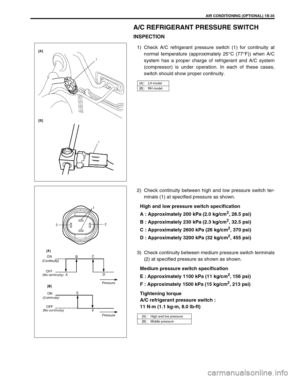
1) Check A/C refrigerant pressure switch (1) for continuity at
normal temperature (approximately 25°C (77°F)) when A/C
system has a proper charge of refrigerant and A/C system
(compressor) is under operation. In each of these cases,
switch should show proper continuity.
2) Check continuity between high and low pressure switch ter-
minals (1) at specified pressure as shown.
High and low pressure switch specification
A : Approximately 200 kPa (2.0 kg/cm
2, 28.5 psi)
B : Approximately 230 kPa (2.3 kg/cm
2, 32.5 psi)
C : Approximately 2600 kPa (26 kg/cm
2, 370 psi)
D : Approximately 3200 kPa (32 kg/cm
2, 455 psi)
3) Check continuity between medium pressure switch terminals
(2) at specified pressure as shown as shown.
Medium pressure switch specification
E : Approximately 1100 kPa (11 kg/cm
2, 156 psi)
F : Approximately 1500 kPa (15 kg/cm
2, 213 psi)
Tightening torque
A/C refrigerant pressure switch :
11 N·m (1.1 kg-m, 8.0 lb-ft)
[A] : LH model
[B] : RH model
[A] : High and low pressure
[B] : Middle pressure
Page 103 of 698
1B-38 AIR CONDITIONING (OPTIONAL)
MAGNET CLUTCH
INSPECTION
Check clutch plate and clutch pulley for wear and oil soaked
conditions respectively.
Check clutch pulley bearing for noise, wear and grease leak-
age.
Measure clutch coil for resistance at 20°C (68°F).
If the measured resistance does not remain within tolerance,
replace magnet clutch assembly.
Clutch coil resistance
: 3.4 – 4.1
Ω
ΩΩ Ω
1. Compressor thermal switch 6. Clutch coil a. Front head bolt
: Tighten bolt (a) first, and next (b)
2. Compressor body 7. Clutch pulley b. Front head bolt
: Tighten bolt (a) first, and next (b)
3. O-ring 8. Circlip c. Clutch plate bolt
4. Lip type seal 9. Circlip Tightening torque
5. Front head 10. Clutch plate Do not reuse.