2000 SUZUKI SWIFT torque
[x] Cancel search: torquePage 106 of 698

AIR CONDITIONING (OPTIONAL) 1B-41
4) Adjust clearance, between clutch plate (1) and clutch pulley
(2) by putting shim on compressor shaft.
Clearance between clutch plate and clutch pulley
“a” : 0.3 – 0.6 mm (0.012 - 0.024 in.)
5) Tighten new clutch plate bolt (2) to specified torque as
shown.
Tightening torque
Clutch plate bolt (a) : 14 N·m (1.4 kg-m, 10.5 lb-ft)
Special tool
(A) : 09991-06020
LIP TYPE SEAL
REMOVAL
1) Remove magnet clutch referring to “MAGNET CLUTCH” in
this section.
2) Remove front head (1) mounting bolts (2).
3) Remove front head (1) by pushing cylinder shaft (2).
4) Remove O-ring (3).
1. Clutch plate
3. Washer
NOTE:
Be careful not to remove cylinder from front head.
Page 108 of 698

AIR CONDITIONING (OPTIONAL) 1B-43
6) Tighten new front head mounting bolts (a), (b).
Tightening torque
Front head bolt (a) : 9 N·m (0.9 kg-m, 6.5 lb-ft)
Front head bolt (b) : 22 N·m (2.2 kg-m, 16.0 lb-ft)
REQUIRED SERVICE MATERIAL
NOTE:
Be sure to use new front head mounting bolts.
Tighten bolt (a) first, and next (b).
MaterialRecommended SUZUKI product
(Part Number)Use
Compressor oil
(Refrigerant oil)COMPRESSOR OIL RS20 (150 cc)
99000-99088O-ring
Each component
Refrigerant REFRIGERANT DRUM (200 g)
95794-50G00Refrigerant charge
Sealant SUZUKI BOND No.1216B
99000-31160Cooling unit
Page 112 of 698

STEERING, SUSPENSION, WHEELS AND TIRES 3-3
Hard Steering
Tire not adequately inflated Inflate tires to proper pressure.
Malfunction of power steering system Check and correct.
Bind in tie rod end ball studs or lower ball joints Replace tie rod end or front sus-
pension arm.
Disturbed front end alignment Check and adjust front end align-
ment.
Rack and pinion adjustment Check and adjust rack and pinion
torque.
Bind in steering column Repair or replace.
Too Much Play in
SteeringWheel bearings worn Replace.
Loose steering gear case bolts Tighten.
Rack and pinion adjustments Check and adjust rack and pinion
torque.
Worn steering shaft joints Replace joint.
Worn tie rod ends or tie rod inside ball joints Replace tie rod end or tie rod.
Worn lower ball joints Replace front suspension control
arm.
Poor Returnability
Bind in tie rod end ball studs Replace tie rod end.
Bind in ball joints Replace.
Bind in steering column Repair or replace.
Poorly lubricated rack and pinion Check, repair or lubricate rack and
pinion.
Disturbed front end alignment Check and adjust front end align-
ment.
Rack and pinion adjustment Check and adjust rack and pinion
torque.
Tires not adequately inflated Adjust tire pressure.
Rack and Pinion Noise
(Rattle or Chuckle)Loose steering gear case bolts Tighten.
Worn rack bush Replace.
Rack and pinion adjustment Check and adjust rack and pinion
torque.
Abnormal Noise,
Front EndWorn, sticky or loose tie rod ends, lower ball
joints, tie rod inside ball joints or drive shaft
jointsReplace tie rod end, suspension
arm, tie rod or drive shaft joint.
Damaged struts or mountings Repair or replace.
Worn suspension arm bushings Replace.
Loose stabilizer bar Tighten bolts or nuts, replace
bushes.
Loose wheel nuts Tighten wheel nuts.
Loose suspension bolts or nuts Tighten suspension bolts or nuts.
Broken or otherwise damaged wheel bearings Replace.
Broken suspension springs Replace.
Poorly lubricated or worn strut bearings Replace strut bearing. Condition Possible Cause Correction
Page 113 of 698

3-4 STEERING, SUSPENSION, WHEELS AND TIRES
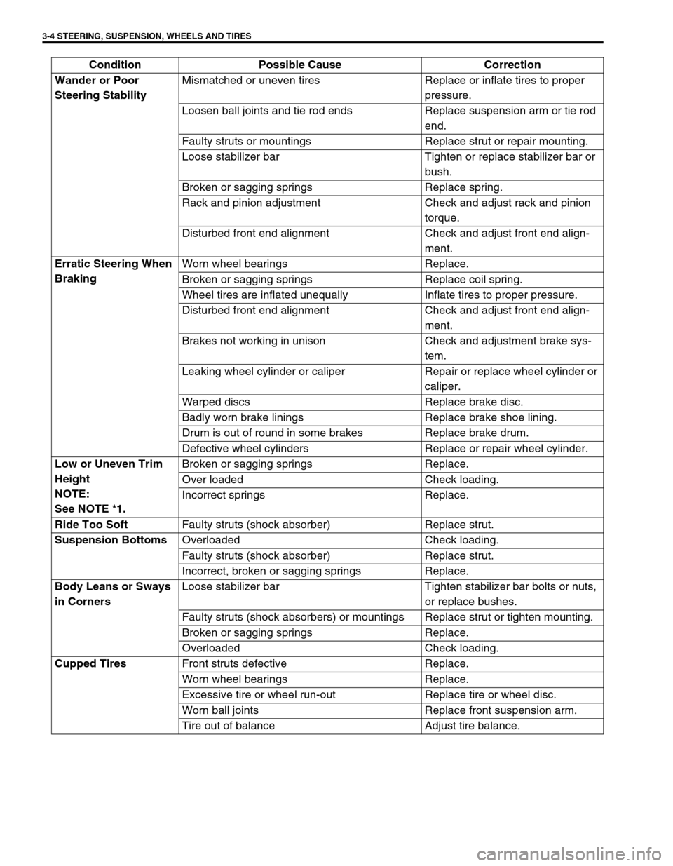
Wander or Poor
Steering StabilityMismatched or uneven tires Replace or inflate tires to proper
pressure.
Loosen ball joints and tie rod ends Replace suspension arm or tie rod
end.
Faulty struts or mountings Replace strut or repair mounting.
Loose stabilizer bar Tighten or replace stabilizer bar or
bush.
Broken or sagging springs Replace spring.
Rack and pinion adjustment Check and adjust rack and pinion
torque.
Disturbed front end alignment Check and adjust front end align-
ment.
Erratic Steering When
BrakingWorn wheel bearings Replace.
Broken or sagging springs Replace coil spring.
Wheel tires are inflated unequally Inflate tires to proper pressure.
Disturbed front end alignment Check and adjust front end align-
ment.
Brakes not working in unison Check and adjustment brake sys-
tem.
Leaking wheel cylinder or caliper Repair or replace wheel cylinder or
caliper.
Warped discs Replace brake disc.
Badly worn brake linings Replace brake shoe lining.
Drum is out of round in some brakes Replace brake drum.
Defective wheel cylinders Replace or repair wheel cylinder.
Low or Uneven Trim
Height
NOTE:
See NOTE *1.Broken or sagging springs Replace.
Over loaded Check loading.
Incorrect springs Replace.
Ride Too Soft
Faulty struts (shock absorber) Replace strut.
Suspension Bottoms
Overloaded Check loading.
Faulty struts (shock absorber) Replace strut.
Incorrect, broken or sagging springs Replace.
Body Leans or Sways
in CornersLoose stabilizer bar Tighten stabilizer bar bolts or nuts,
or replace bushes.
Faulty struts (shock absorbers) or mountings Replace strut or tighten mounting.
Broken or sagging springs Replace.
Overloaded Check loading.
Cupped Tires
Front struts defective Replace.
Worn wheel bearings Replace.
Excessive tire or wheel run-out Replace tire or wheel disc.
Worn ball joints Replace front suspension arm.
Tire out of balance Adjust tire balance. Condition Possible Cause Correction
Page 120 of 698

FRONT END ALIGNMENT 3A-3
DIAGNOSIS
DIAGNOSIS TABLE
For the details, refer to Section 3.
PRELIMINARY CHECKS PRIOR TO ADJUSTING FRONT ALIGNMENT
Steering and vibration complaints are not always the result of improper alignment. An additional item to be
checked is the possibility of tire lead due to worn or improperly manufactured tires. “Lead” is the deviation of the
vehicle from a straight path on a level road without hand pressure on the steering wheel. Procedure for deter-
mining the presence of a tire lead problem contains in SECTION 3. Before making any adjustment affecting toe
setting, the following checks and inspections should be made to ensure correctness of alignment readings and
alignment adjustments:
1) Check all tires for proper inflation pressures and approximately the same tread wear.
2) Check for loose of ball joints. Check tie rod ends; if excessive looseness is noted, it must be corrected
before adjusting.
3) Check for run-out of wheels and tires.
4) Check vehicle trim heights; if out of limits and a correction is to be made, it must be made before adjusting
toe.
5) Check for loose of suspension arms.
6) Check for loose or missing stabilizer bar attachments.
7) Consideration must be given to excess loads, such as tool boxes. If this excess load is normally carried in
vehicle, it should remain in vehicle during alignment checks.
8) Consider condition of equipment being used to check alignment and follow manufacturer's instructions.
9) Regardless of equipment used to check alignment, vehicle must be on a level surface both fore and aft and
transversely.
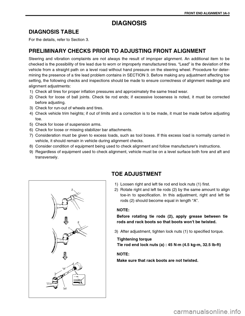
TOE ADJUSTMENT
1) Loosen right and left tie rod end lock nuts (1) first.
2) Rotate right and left tie rods (2) by the same amount to align
toe-in to specification. In this adjustment, right and left tie
rods (2) should become equal in length “A”.
3) After adjustment, tighten lock nuts (1) to specified torque.
Tightening torque
Tie rod end lock nuts (a) : 45 N·m (4.5 kg-m, 32.5 lb-ft) NOTE:
Before rotating tie rods (2), apply grease between tie
rods and rack boots so that boots won't be twisted.
NOTE:
Make sure that rack boots are not twisted.
Page 122 of 698

MANUAL RACK AND PINION 3B-1
6F1
6F2
6G
6H
7A
3B
7C1
7D
7E
7F
8A
8B
8C
8D
8E
9
10
10A
10B
SECTION 3B
MANUAL RACK AND PINION
CONTENTS
GENERAL DESCRIPTION .............................. 3B-2
DIAGNOSIS ..................................................... 3B-3
ON-VEHICLE SERVICE .................................. 3B-4
LUBRICATION ............................................. 3B-4
TIE ROD END .............................................. 3B-6
MANUAL RACK AND PINION ASSEMBLY
(STEERING GEAR CASE) .......................... 3B-7
RACK BOOT/TIE ROD .............................. 3B-10STEERING RACK PLUNGER ................... 3B-12
STEERING PINION ................................... 3B-14
STEERING RACK...................................... 3B-15
PINION BEARING ..................................... 3B-17
RACK BUSHING ........................................ 3B-18
REQUIRED SERVICE MATERIAL................ 3B-19
SPECIAL TOOL ............................................ 3B-20
WARNING:
For vehicles equipped with a Air Bag System
Service on or around air bag system components or wiring must be performed only by an autho-
rized suzuki dealer. Please observe all WARNINGS and CAUTIONS in SECTION 10B and Precau-
tions, Air Bag System Components and Wiring Location view in Section 10B before performing
service on or around air bag system components or wiring. Failure to follow WARNINGS could
result in unintended activation of the system or could render the system inoperative. Either of these
two conditions may result in severe injury.
Technical service work must be started at least 90 seconds after the ignition switch is turned to the
“LOCK” position and the negative cable is disconnected from the battery. Otherwise, the system
may be deployed by reserve energy in the Sensing and Diagnostic Module (SDM).
NOTE:
All steering gear fasteners are important attaching parts in that they could affect the performance of
vital parts and systems, and/or could result in major repair expense. They must be replaced with one
of the same part number or with an equivalent part if replacement becomes necessary. Do not use a
replacement part of lesser quality or substitute design. Torque values must be used as specified dur-
ing reassembly to assure proper retention of these parts.
Page 125 of 698

3B-4 MANUAL RACK AND PINION
STEERING WHEEL CHECK
Check steering wheel for play and rattle, holding vehicle in
straight forward condition on the ground.
Steering wheel play
“a” : 0 – 30 mm (0 – 1.1 in.)
If steering wheel play is not within specification, inspect as follows
and replace if found defective.
Tie-rod end ball stud for wear (ball stud should move when
more than 2 kg-cm torque is applied.)
Lower ball joint for wear
Steering shaft joint for wear
Steering pinion or rack gear for wear or breakage
Each part for looseness
ON-VEHICLE SERVICE
LUBRICATION
When inner parts of the steering gear case were disassembled, they should be washed clean before reassem-
bly. It is recommended to use the grease as given below where grease application is indicated in the text.
✱
✱✱ ✱ SUZUKI SUPER GREASE (E) 99000-25050, or Lithium grease
(applicable for –40°C ~ 130°C or 104°F ~ 266°F)
Page 128 of 698

MANUAL RACK AND PINION 3B-7
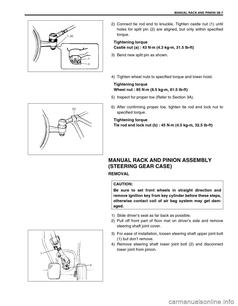
2) Connect tie rod end to knuckle. Tighten castle nut (1) until
holes for split pin (2) are aligned, but only within specified
torque.
Tightening torque
Castle nut (a) : 43 N·m (4.3 kg-m, 31.5 lb-ft)
3) Bend new split pin as shown.
4) Tighten wheel nuts to specified torque and lower hoist.
Tightening torque
Wheel nut : 85 N·m (8.5 kg-m, 61.5 lb-ft)
5) Inspect for proper toe (Refer to Section 3A).
6) After confirming proper toe, tighten tie rod end lock nut to
specified torque.
Tightening torque
Tie rod end lock nut (b) : 45 N·m (4.5 kg-m, 32.5 lb-ft)
MANUAL RACK AND PINION ASSEMBLY
(STEERING GEAR CASE)
REMOVAL
1) Slide driver’s seat as far back as possible.
2) Pull off front part of floor mat on driver’s side and remove
steering shaft joint cover.
3) For ease of installation, loosen steering shaft upper joint bolt
(1) but don’t remove.
4) Remove steering shaft lower joint bolt (2) and disconnect
lower joint from pinion.
CAUTION:
Be sure to set front wheels in straight direction and
remove ignition key from key cylinder before these steps,
otherwise contact coil of air bag system may get dam-
aged.