Page 285 of 698
5-12 BRAKES
2) Start engine while depressing brake pedal. If pedal travel
increases a little, operation is satisfactory. But no change in
pedal travel indicates malfunction.
CHECK AIR TIGHTNESS UNDER LOAD
1) With engine running, depress brake pedal. Then stop engine
while holding brake pedal depressed.
2) Hold brake pedal depressed for 30 seconds. If pedal height
does not change, condition is good. But it isn’t if pedal rises.
FLUID PRESSURE TEST (IF EQUIPPED WITH
LSPV)
Test procedure for LSPV assembly is as follows.
Before testing, confirm the following.
Fuel tank is filled with fuel fully.
Vehicle is equipped with spare tire, tools, jack and jack han-
dle.
H: Hold
H: Hold
T: 30 seconds
Page 524 of 698

ENGINE MECHANICAL (M13 ENGINE) 6A1-23
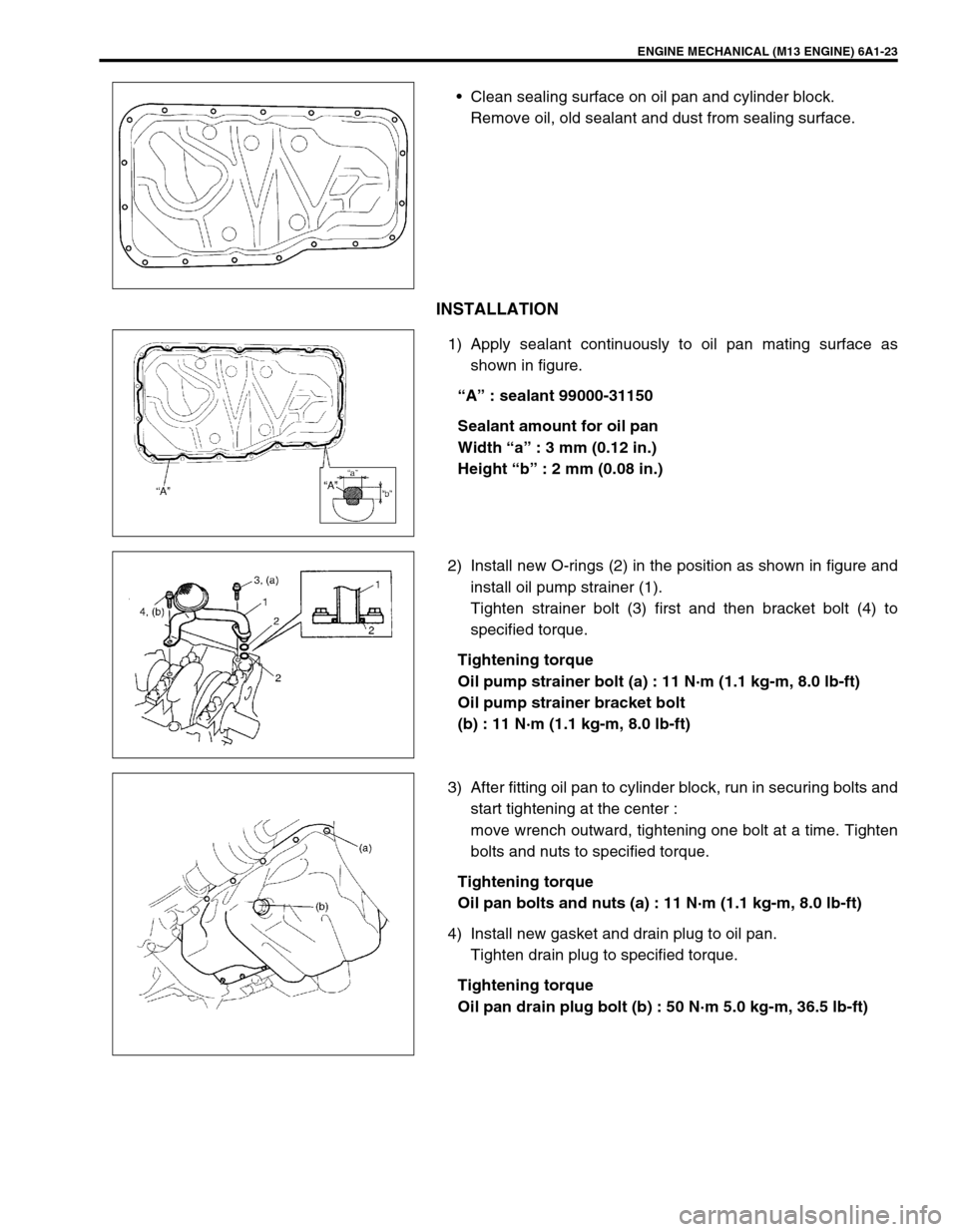
Clean sealing surface on oil pan and cylinder block.
Remove oil, old sealant and dust from sealing surface.
INSTALLATION
1) Apply sealant continuously to oil pan mating surface as
shown in figure.
“A” : sealant 99000-31150
Sealant amount for oil pan
Width “a” : 3 mm (0.12 in.)
Height “b” : 2 mm (0.08 in.)
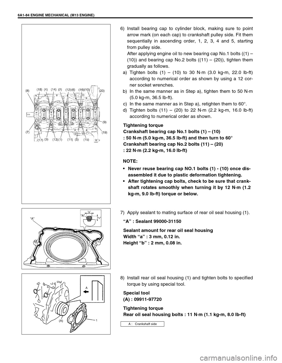
2) Install new O-rings (2) in the position as shown in figure and
install oil pump strainer (1).
Tighten strainer bolt (3) first and then bracket bolt (4) to
specified torque.
Tightening torque
Oil pump strainer bolt (a) : 11 N·m (1.1 kg-m, 8.0 lb-ft)
Oil pump strainer bracket bolt
(b) : 11 N·m (1.1 kg-m, 8.0 lb-ft)
3) After fitting oil pan to cylinder block, run in securing bolts and
start tightening at the center :
move wrench outward, tightening one bolt at a time. Tighten
bolts and nuts to specified torque.
Tightening torque
Oil pan bolts and nuts (a) : 11 N·m (1.1 kg-m, 8.0 lb-ft)
4) Install new gasket and drain plug to oil pan.
Tighten drain plug to specified torque.
Tightening torque
Oil pan drain plug bolt (b) : 50 N·m 5.0 kg-m, 36.5 lb-ft)
Page 529 of 698
6A1-28 ENGINE MECHANICAL (M13 ENGINE)
INSTALLATION
Reverse removal procedure to install timing chain cover, noting
the following points.
1) Apply sealant “A” to mating surface of cylinder and cylinder
head and “B” to mating surface of timing chain cover as
shown in figure.
“A” : Sealant 99000-31140
“B” : Sealant 99000-31150
Sealant amount for timing chain cover
Width “a” : 3 mm, 0.12 in.
Height “b” : 2 mm, 0.08 in.
2) Apply engine oil to oil seal lip, then install timing chain cover
(1).
Tighten bolts and nut to specified torque.
Tightening torque
Timing chain cover bolts (a) : 23 N·m (2.3 kg-m, 17.0 lb-ft)
3) Install engine right mounting (1) with bracket to timing chain
cover and body.
Tighten bolts to specified torque.
Tightening torque
Engine mounting bolt (a) : 75 N·m (7.5 kg-m, 54.5 lb-ft)
Engine mounting bracket bolt
(b) : 55 N·m (5.5 kg-m, 40.0 lb-ft)
4) Remove support device (2).
NOTE:
Before installing timing chain cover, check that pin is
securely fitted.
Page 541 of 698

6A1-40 ENGINE MECHANICAL (M13 ENGINE)
7) Remove tappets (2) with shims (1).
INSPECTION
Cam Wear
Using a micrometer, measure cam height “a”. If measured height
is below its limit, replace camshaft.
Cam height “a” of camshaft
Camshaft Runout
Set camshaft between two “V” blocks, and measure its runout by
using a dial gauge.
If measured runout exceeds below limit, replace camshaft.
Camshaft runout limit
: 0.10 mm (0.0039 in.)
Camshaft Journal Wear
Check camshaft journals and camshaft housings for pitting,
scratches, wear or damage.
If any malcondition is found, replace camshaft or cylinder head
with housing. Never replace cylinder head without replacing hous-
ings.
Check clearance by using gaging plastic. Checking procedure is
as follows.
1) Clean housings and camshaft journals.
2) Remove all tappets with shims.
3) Install camshafts to cylinder head.
4) Place a piece of gaging plastic to full width of journal of cam-
shaft (parallel to camshaft).
5) Install camshaft housing.
Standard Limit
Intake cam 44.919 – 45.089 mm
(1.768 – 1.775 in.)44.81 mm
(1.764 in.)
Exhaust cam
(ID mark (1) on
sprocket: EXA)44.202 – 44.362 mm
(1.740 – 1.747 in.)44.08 mm
(1.735 in.)
Exhaust cam
(ID mark (1) on
sprocket: EXB)44.399 – 44.559 mm
(1.748 – 1.754 in.)44.28 mm
(1.743 in.)
Page 585 of 698

6A1-84 ENGINE MECHANICAL (M13 ENGINE)
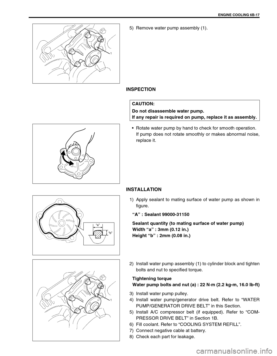
6) Install bearing cap to cylinder block, making sure to point
arrow mark (on each cap) to crankshaft pulley side. Fit them
sequentially in ascending order, 1, 2, 3, 4 and 5, starting
from pulley side.
After applying engine oil to new bearing cap No.1 bolts ((1) –
(10)) and bearing cap No.2 bolts ((11) – (20)), tighten them
gradually as follows.
a) Tighten bolts (1) – (10) to 30 N·m (3.0 kg-m, 22.0 lb-ft)
according to numerical order as shown by using a 12 cor-
ner socket wrenches.
b) In the same manner as in Step a), tighten them to 50 N·m
(5.0 kg-m, 36.5 lb-ft).
c) In the same manner as in Step a), retighten them to 60°.
d) Tighten bolts (11) – (20) to 22 N·m (2.2 kg-m, 16.0 lb-ft)
according to numerical order as shown.
Tightening torque
Crankshaft bearing cap No.1 bolts (1) – (10)
: 50 N·m (5.0 kg-m, 36.5 lb-ft) and then turn to 60°
Crankshaft bearing cap No.2 bolts (11) – (20)
: 22 N·m (2.2 kg-m, 16.0 lb-ft)
7) Apply sealant to mating surface of rear oil seal housing (1).
“A” : Sealant 99000-31150
Sealant amount for rear oil seal housing
Width “a” : 3 mm, 0.12 in.
Height “b” : 2 mm, 0.08 in.
8) Install rear oil seal housing (1) and tighten bolts to specified
torque by using special tool.
Special tool
(A) : 09911-97720
Tightening torque
Rear oil seal housing bolts : 11 N·m (1.1 kg-m, 8.0 lb-ft) NOTE:
Never reuse bearing cap NO.1 bolts (1) - (10) once dis-
assembled it due to plastic deformation tightening.
After tightening cap bolts, check to be sure that crank-
shaft rotates smoothly when turning it by 12 N·m (1.2
kg-m, 9.0 lb-ft) torque or below.
A : Crankshaft side
Page 606 of 698

ENGINE COOLING 6B-17
5) Remove water pump assembly (1).
INSPECTION
Rotate water pump by hand to check for smooth operation.
If pump does not rotate smoothly or makes abnormal noise,
replace it.
INSTALLATION
1) Apply sealant to mating surface of water pump as shown in
figure.
“A” : Sealant 99000-31150
Sealant quantity (to mating surface of water pump)
Width “a” : 3mm (0.12 in.)
Height “b” : 2mm (0.08 in.)
2) Install water pump assembly (1) to cylinder block and tighten
bolts and nut to specified torque.
Tightening torque
Water pump bolts and nut (a) : 22 N·m (2.2 kg-m, 16.0 lb-ft)
3) Install water pump pulley.
4) Install water pump/generator drive belt. Refer to “WATER
PUMP/GENERATOR DRIVE BELT” in this Section.
5) Install A/C compressor belt (if equipped). Refer to “COM-
PRESSOR DRIVE BELT” in Section 1B.
6) Fill coolant. Refer to “COOLING SYSTEM REFILL”.
7) Connect negative cable at battery.
8) Check each part for leakage.
CAUTION:
Do not disassemble water pump.
If any repair is required on pump, replace it as assembly.
“a”
“b”