2000 SUZUKI SWIFT Air
[x] Cancel search: AirPage 312 of 698

BRAKES 5-39
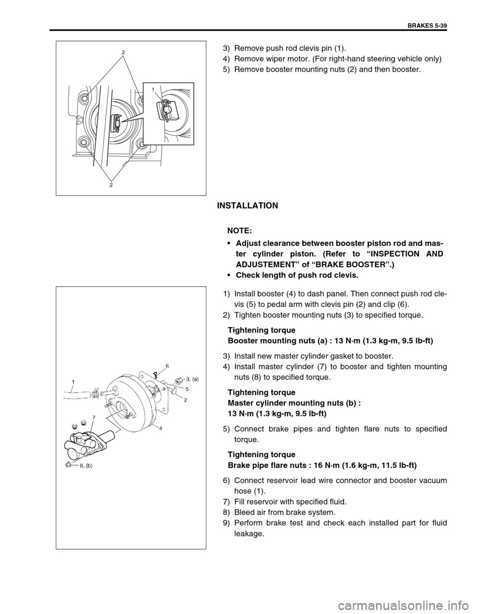
3) Remove push rod clevis pin (1).
4) Remove wiper motor. (For right-hand steering vehicle only)
5) Remove booster mounting nuts (2) and then booster.
INSTALLATION
1) Install booster (4) to dash panel. Then connect push rod cle-
vis (5) to pedal arm with clevis pin (2) and clip (6).
2) Tighten booster mounting nuts (3) to specified torque.
Tightening torque
Booster mounting nuts (a) : 13 N·m (1.3 kg-m, 9.5 lb-ft)
3) Install new master cylinder gasket to booster.
4) Install master cylinder (7) to booster and tighten mounting
nuts (8) to specified torque.
Tightening torque
Master cylinder mounting nuts (b) :
13 N·m (1.3 kg-m, 9.5 lb-ft)
5) Connect brake pipes and tighten flare nuts to specified
torque.
Tightening torque
Brake pipe flare nuts : 16 N·m (1.6 kg-m, 11.5 lb-ft)
6) Connect reservoir lead wire connector and booster vacuum
hose (1).
7) Fill reservoir with specified fluid.
8) Bleed air from brake system.
9) Perform brake test and check each installed part for fluid
leakage.
1
2
2
NOTE:
Adjust clearance between booster piston rod and mas-
ter cylinder piston. (Refer to “INSPECTION AND
ADJUSTEMENT” of “BRAKE BOOSTER”.)
Check length of push rod clevis.
Page 314 of 698

BRAKES 5-41
BRAKE HOSE/PIPE
FRONT BRAKE HOSE/PIPE
REMOVAL
1) Raise and support vehicle properly. Remove tire and wheel.
2) Clean dirt and foreign material from both flexible hose end and pipe end fittings.
3) Remove brake flexible hose or pipe.
INSTALLATION
Reverse brake flexible hose installation procedure, noting the followings.
Make sure that steering wheel is in straight-forward position and flexible hose has not twist or kink.
Check to make sure that flexible hose doesn’t contact any part of suspension, both in extreme right and
extreme left turn conditions. If it does at any point, remove and correct. Fill and maintain brake fluid level in
reservoir.
Bleed brake system. Refer to “AIR BLEEDING OF BRAKE SYSTEM”.
Perform brake test and check installed part for fluid leakage. NOTE:
This operation is not necessary when removing pipes connecting master cylinder.
Page 317 of 698

5-44 BRAKES
REAR BRAKE HOSE/PIPE
REMOVAL
1) Raise and support vehicle properly. Remove tire and wheel.
2) Clean dirt and foreign material from both flexible hose end and pipe end fittings.
3) Remove brake flexible hose or pipe.
INSTALLATION
Reverse brake flexible hose installation procedure, nothing the followings.
Fill and maintain brake fluid level in reservoir.
Bleed brake system. Refer to “AIR BLEEDING OF BRAKE SYSTEM”.
Perform brake test and check each installed part for fluid leakage.
Never reuse protector nut once removed. Be sure to use a new one.
Install clamps properly referring to figure below and tighten bolts.
When installing hose, make sure that it has no twist or kink.
Page 322 of 698

BRAKES 5-49
INSTALLATION
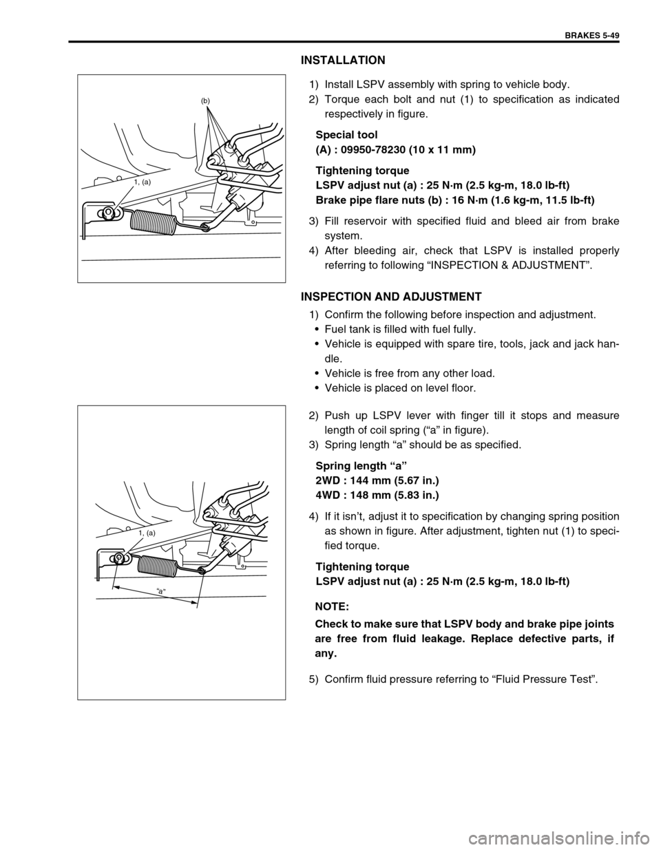
1) Install LSPV assembly with spring to vehicle body.
2) Torque each bolt and nut (1) to specification as indicated
respectively in figure.
Special tool
(A) : 09950-78230 (10 x 11 mm)
Tightening torque
LSPV adjust nut (a) : 25 N·m (2.5 kg-m, 18.0 lb-ft)
Brake pipe flare nuts (b) : 16 N·m (1.6 kg-m, 11.5 lb-ft)
3) Fill reservoir with specified fluid and bleed air from brake
system.
4) After bleeding air, check that LSPV is installed properly
referring to following “INSPECTION & ADJUSTMENT”.
INSPECTION AND ADJUSTMENT
1) Confirm the following before inspection and adjustment.
Fuel tank is filled with fuel fully.
Vehicle is equipped with spare tire, tools, jack and jack han-
dle.
Vehicle is free from any other load.
Vehicle is placed on level floor.
2) Push up LSPV lever with finger till it stops and measure
length of coil spring (“a” in figure).
3) Spring length “a” should be as specified.
Spring length “a”
2WD : 144 mm (5.67 in.)
4WD : 148 mm (5.83 in.)
4) If it isn’t, adjust it to specification by changing spring position
as shown in figure. After adjustment, tighten nut (1) to speci-
fied torque.
Tightening torque
LSPV adjust nut (a) : 25 N·m (2.5 kg-m, 18.0 lb-ft)
5) Confirm fluid pressure referring to “Fluid Pressure Test”.
1, (a)
(b)
NOTE:
Check to make sure that LSPV body and brake pipe joints
are free from fluid leakage. Replace defective parts, if
any.
1, (a)
“a”
Page 326 of 698

ANTILOCK BRAKE SYSTEM (ABS) 5E-1
6F1
6F2
6G
6H
6K
7A
7A1
7B1
7C1
7D
7E
7F
8A
8B
8C
8D
8E
5E
9
10
10A
10B
SECTION 5E
ANTILOCK BRAKE SYSTEM (ABS)
CONTENTS
GENERAL DESCRIPTION .............................. 5E-2
COMPONENTS/PARTS LOCATION AND
BRAKE HOSE/PIPE ROUTING ................... 5E-2
SYSTEM SCHEMATIC ................................ 5E-4
ABS HYDRAULIC UNIT/CONTROL
MODULE ASSEMBLY ................................. 5E-5
SELF-DIAGNOSIS FUNCTION................ 5E-5
FAIL-SAFE FUNCTION............................ 5E-5
SYSTEM CIRCUIT ....................................... 5E-6
DIAGNOSIS ..................................................... 5E-8
PRECAUTION IN DIAGNOSING
TROUBLES .................................................. 5E-8
ABS DIAGNOSTIC FLOW TABLE ............... 5E-9
ABS WARNING LAMP CHECK ................. 5E-12
EBD WARNING LAMP (BRAKE
WARNING LAMP) CHECK ........................ 5E-12
TABLE – A ABS WARNING LAMP
CIRCUIT CHECK – LAMP DOES NOT
COME “ON” AT IGNITION SWITCH ON.... 5E-13
TABLE – B ABS WARNING LAMP
CIRCUIT CHECK – LAMP COMES
“ON” STEADY ............................................ 5E-14TABLE – C ABS WARNING LAMP
CIRCUIT CHECK – THE LAMP FLASHES
CONTINUOUSLY WHILE IGNITION
SWITCH IS ON .......................................... 5E-15
TABLE – D CODE (DTC) IS NOT
OUTPUTTED EVEN WITH DIAGNOSIS
SWITCH TERMINAL CONNECTED TO
GROUND ................................................... 5E-16
TABLE – E EBD WARNING LAMP
(BRAKE WARNING LAMP) CHECK
– LAMP COMES “ON” STEADY ................ 5E-17
DIAGNOSTIC TROUBLE CODE
(DTC) CHECK (USING ABS WARNING
LAMP) ........................................................ 5E-18
DIAGNOSTIC TROUBLE CODE (DTC)
CHECK (USING SUZUKI SCAN TOOL).... 5E-19
DIAGNOSTIC TROUBLE CODE
(DTC) CLEARANCE .................................. 5E-19
DIAGNOSTIC TROUBLE CODE (DTC)
TABLE........................................................ 5E-20
DTC C1013 (DTC 13) – SYSTEM
SPECIFICATIONS DIFFERENT FROM ABS
CONTROL MODULE SPECIFICATIONS .. 5E-22 WARNING:
For vehicles equipped with Supplemental Restraint (Air Bag) System :
Service on and around the air bag system components or wiring must be performed only by an
authorized SUZUKI dealer. Refer to “Air Bag System Components and Wiring Location View” under
“General Description” in air bag system section in order to confirm whether you are performing ser-
vice on or near the air bag system components or wiring. Please observe all WARNINGS and “Ser-
vice Precautions” under “On-Vehicle Service” in air bag system section before performing service
on or around the air bag system components or wiring. Failure to follow WARNINGS could result in
unintentional activation of the system or could render the system inoperative. Either of these two
conditions may result in severe injury.
Technical service work must be started at least 90 seconds after the ignition switch is turned to the
“LOCK” position and the negative cable is disconnected from the battery. Otherwise, the system
may be activated by reserve energy in the Sensing and Diagnostic Module (SDM).
NOTE:
All brake fasteners are important attaching parts in that they could affect the performance of vital
parts and systems, and/or could result in major repair expense. They must be replaced with one of
same part number or with an equivalent part if replacement becomes necessary. Do not use a replace-
ment part of lesser quality or substitute design. Torque values must be used as specified during reas-
sembly to assure proper retention of all parts. There is to be no welding as it may result in extensive
damage and weakening of the metal.
Page 334 of 698

ANTILOCK BRAKE SYSTEM (ABS) 5E-9
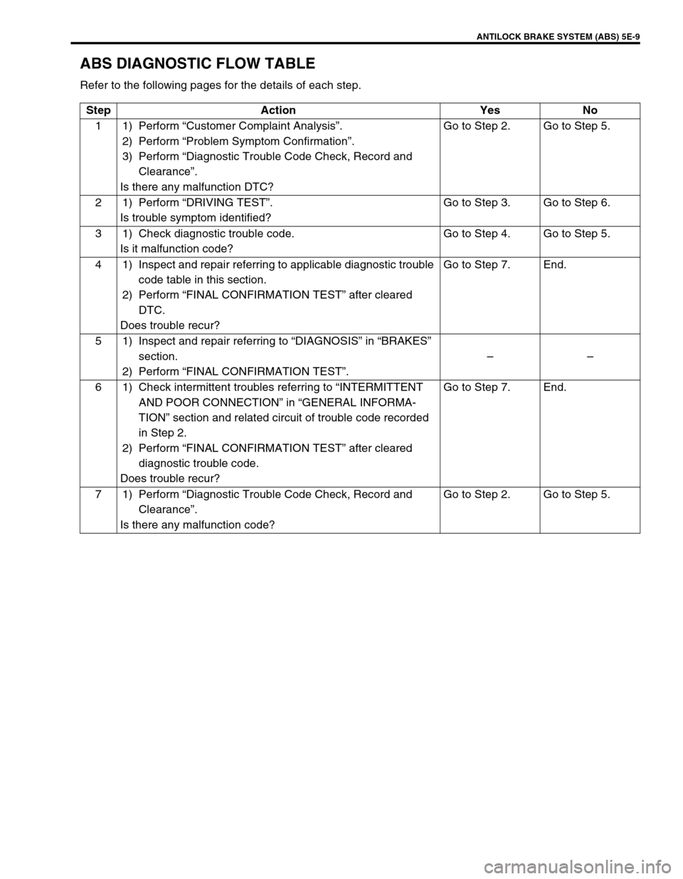
ABS DIAGNOSTIC FLOW TABLE
Refer to the following pages for the details of each step.
Step Action Yes No
11)Perform “Customer Complaint Analysis”.
2) Perform “Problem Symptom Confirmation”.
3) Perform “Diagnostic Trouble Code Check, Record and
Clearance”.
Is there any malfunction DTC?Go to Step 2. Go to Step 5.
21)Perform “DRIVING TEST”.
Is trouble symptom identified?Go to Step 3. Go to Step 6.
3 1) Check diagnostic trouble code.
Is it malfunction code?Go to Step 4. Go to Step 5.
4 1) Inspect and repair referring to applicable diagnostic trouble
code table in this section.
2) Perform “FINAL CONFIRMATION TEST” after cleared
DTC.
Does trouble recur?Go to Step 7. End.
5 1) Inspect and repair referring to “DIAGNOSIS” in “BRAKES”
section.
2) Perform “FINAL CONFIRMATION TEST”.––
6 1) Check intermittent troubles referring to “INTERMITTENT
AND POOR CONNECTION” in “GENERAL INFORMA-
TION” section and related circuit of trouble code recorded
in Step 2.
2) Perform “FINAL CONFIRMATION TEST” after cleared
diagnostic trouble code.
Does trouble recur?Go to Step 7. End.
71)Perform “Diagnostic Trouble Code Check, Record and
Clearance”.
Is there any malfunction code?Go to Step 2. Go to Step 5.
Page 335 of 698

5E-10 ANTILOCK BRAKE SYSTEM (ABS)
1) MALFUNCTION ANALYSIS
a) Customer Complaint Analysis
Record details of the problem (failure, complaint) and how it occurred as described by the customer.
For this purpose, use of such a questionnaire form as shown below will facilitate collecting information to
the point required for proper analysis and diagnosis.
CUSTOMER QUESTIONNAIRE (EXAMPLE)
b) Problem Symptom Confirmation
Check if what the customer claimed in “CUSTOMER QUESTIONNAIRE” is actually found in the vehicle
and if that symptom is found, whether it is identified as a failure. (This step should be shared with the cus-
tomer if possible.) Check warning lamps related to brake system referring to “EBD WARNING LAMP
(BRAKE WARNING LAMP) CHECK” and “ABS WARNING LAMP CHECK” in this section.
Page 336 of 698

ANTILOCK BRAKE SYSTEM (ABS) 5E-11
c) Diagnostic Trouble Code (DTC) Check, Record and Clearance
Perform “DIAGNOSTIC TROUBLE CODE CHECK” procedure in this section, record it and then clear it
referring to “DIAGNOSTIC TROUBLE CODE CLEARANCE” in this section.
If the malfunction DTC which was once displayed and then cleared cannot be detected (indicated) again
when the ignition switch is turned ON, attempt to diagnose the trouble based on the DTC recorded in this
step may mislead the diagnosis or make diagnosing difficult. Proceed to Step 2) to check control module
for proper self-diagnosis function.
If the malfunction DTC which was once displayed and then cleared can be detected (indicated) again when
ignition switch is turned ON, proceed to Step 3).
2) DRIVING TEST
Test drive the vehicle at 40 km/h for more than a minute and check if any trouble symptom (such as abnor-
mal lighting of ABS warning light) exists.
If the malfunction DTC is confirmed again at ignition switch ON, driving test as described in above is not nec-
essary. Proceed to Step 3).
3) DIAGNOSTIC TROUBLE CODE CHECK
Recheck diagnostic trouble code referring to “DTC CHECK” as shown in the following page.
4) DIAGNOSTIC TROUBLE CODE FLOW TABLE
According to Diagnostic flow table for the diagnostic trouble code confirmation in Step 3), locate the cause of
the trouble, namely in a sensor, switch, wire harness, connector, actuator assembly or other part and repair
or replace faulty parts.
5)“DIAGNOSIS” IN “BRAKES” SECTION
Check the parts or system suspected as a possible cause referring to “DIAGNOSIS” in “BRAKES” section
and based on symptoms appearing on the vehicle (symptom obtained through Steps 1)-a, 1)-b and 2) and
repair or replace faulty parts, if any).
6) CHECK FOR INTERMITTENT PROBLEM
Check parts where an intermittent trouble is easy to occur (e.g., wire harness, connector, etc.), referring to
“INTERMITTENT TROUBLE” in “GENERAL INFORMATION” section and related circuit of trouble code
recorded in Step 1)-c.
7) FINAL CONFIRMATION TEST
Confirm that the problem symptom has gone and the ABS is free from any abnormal conditions. If what has
been repaired is related to the malfunction DTC, clear the DTC once and perform test driving and confirm
that no DTC is indicated.