Page 289 of 698
5-16 BRAKES
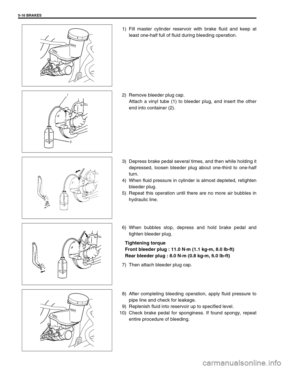
1) Fill master cylinder reservoir with brake fluid and keep at
least one-half full of fluid during bleeding operation.
2) Remove bleeder plug cap.
Attach a vinyl tube (1) to bleeder plug, and insert the other
end into container (2).
3) Depress brake pedal several times, and then while holding it
depressed, loosen bleeder plug about one-third to one-half
turn.
4) When fluid pressure in cylinder is almost depleted, retighten
bleeder plug.
5) Repeat this operation until there are no more air bubbles in
hydraulic line.
6) When bubbles stop, depress and hold brake pedal and
tighten bleeder plug.
Tightening torque
Front bleeder plug : 11.0 N·m (1.1 kg-m, 8.0 lb-ft)
Rear bleeder plug : 8.0 N·m (0.8 kg-m, 6.0 lb-ft)
7) Then attach bleeder plug cap.
8) After completing bleeding operation, apply fluid pressure to
pipe line and check for leakage.
9) Replenish fluid into reservoir up to specified level.
10) Check brake pedal for sponginess. If found spongy, repeat
entire procedure of bleeding.
MAX
MIN
MAX
MIN
Page 293 of 698
5-20 BRAKES
DISASSEMBLY
1) Remove piston with air blown into flexible hose bolt installa-
tion hole.
2) Remove cylinder boot (1).
3) Remove piston seal using a thin blade like a thickness
gauge, etc.
4) Remove bleeder plug and cap from caliper.
INSPECTION
Pin Boot and Cylinder Boot
Check boots for breakage, crack and damage.
If defective, replace.CAUTION:
Clean around caliper with brake fluid before disassem-
bly.
WARNING:
Do not apply too highly compressed air which will cause
piston to jump out of cylinder. Place a cloth (1) to prevent
piston from damage. It should be taken out gradually
with moderately compressed air. Do not place your fin-
gers in front of piston when using compressed air.
CAUTION:
Use care not to cause damage to cylinder boot.
1
CAUTION:
Be careful not to damage inside (bore side) of cylinder.
Page 294 of 698
BRAKES 5-21
Piston Seal
Excessive or uneven wear of pad lining may indicate unsmooth
return of piston.
In such case, replace rubber seal.
ASSEMBLY
Assemble parts in reverse order of disassembly, observing the
following instructions.
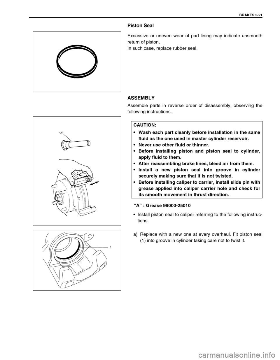
“A” : Grease 99000-25010
Install piston seal to caliper referring to the following instruc-
tions.
a) Replace with a new one at every overhaul. Fit piston seal
(1) into groove in cylinder taking care not to twist it.
CAUTION:
Wash each part cleanly before installation in the same
fluid as the one used in master cylinder reservoir.
Never use other fluid or thinner.
Before installing piston and piston seal to cylinder,
apply fluid to them.
After reassembling brake lines, bleed air from them.
Install a new piston seal into groove in cylinder
securely making sure that it is not twisted.
Before installing caliper to carrier, install slide pin with
grease applied into caliper carrier hole and check for
its smooth movement in thrust direction.
1
Page 296 of 698
BRAKES 5-23
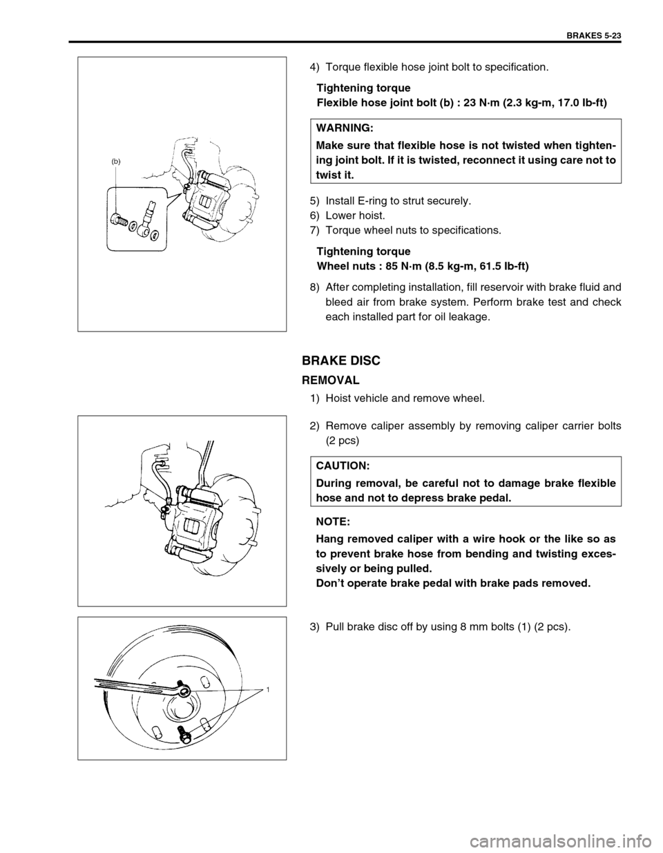
4) Torque flexible hose joint bolt to specification.
Tightening torque
Flexible hose joint bolt (b) : 23 N·m (2.3 kg-m, 17.0 Ib-ft)
5) Install E-ring to strut securely.
6) Lower hoist.
7) Torque wheel nuts to specifications.
Tightening torque
Wheel nuts : 85 N·m (8.5 kg-m, 61.5 Ib-ft)
8) After completing installation, fill reservoir with brake fluid and
bleed air from brake system. Perform brake test and check
each installed part for oil leakage.
BRAKE DISC
REMOVAL
1) Hoist vehicle and remove wheel.
2) Remove caliper assembly by removing caliper carrier bolts
(2 pcs)
3) Pull brake disc off by using 8 mm bolts (1) (2 pcs).WARNING:
Make sure that flexible hose is not twisted when tighten-
ing joint bolt. If it is twisted, reconnect it using care not to
twist it.
CAUTION:
During removal, be careful not to damage brake flexible
hose and not to depress brake pedal.
NOTE:
Hang removed caliper with a wire hook or the like so as
to prevent brake hose from bending and twisting exces-
sively or being pulled.
Don’t operate brake pedal with brake pads removed.
Page 304 of 698
BRAKES 5-31
INSTALLATION
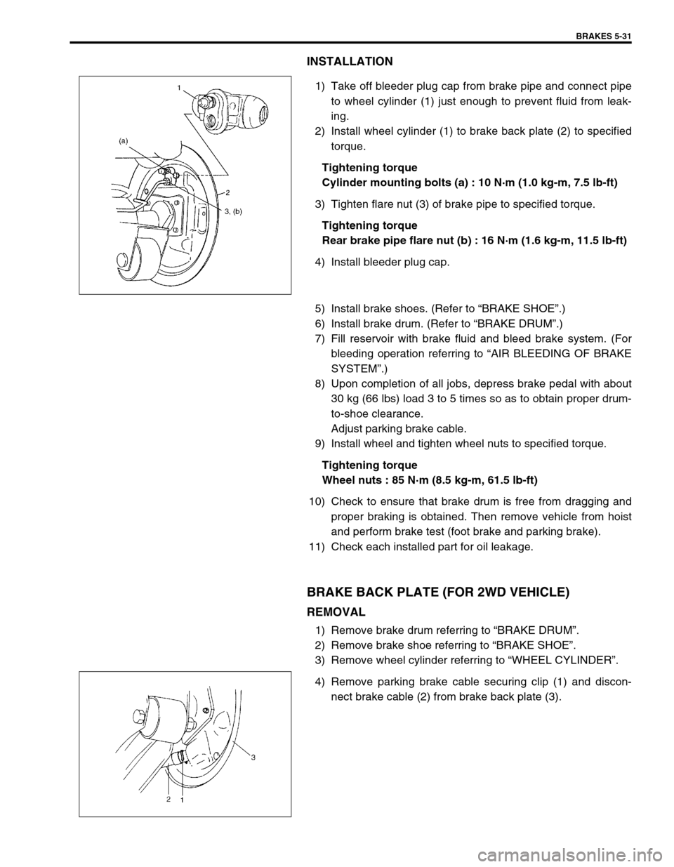
1) Take off bleeder plug cap from brake pipe and connect pipe
to wheel cylinder (1) just enough to prevent fluid from leak-
ing.
2) Install wheel cylinder (1) to brake back plate (2) to specified
torque.
Tightening torque
Cylinder mounting bolts (a) : 10 N·m (1.0 kg-m, 7.5 lb-ft)
3) Tighten flare nut (3) of brake pipe to specified torque.
Tightening torque
Rear brake pipe flare nut (b) : 16 N·m (1.6 kg-m, 11.5 lb-ft)
4) Install bleeder plug cap.
5) Install brake shoes. (Refer to “BRAKE SHOE”.)
6) Install brake drum. (Refer to “BRAKE DRUM”.)
7) Fill reservoir with brake fluid and bleed brake system. (For
bleeding operation referring to “AIR BLEEDING OF BRAKE
SYSTEM”.)
8) Upon completion of all jobs, depress brake pedal with about
30 kg (66 lbs) load 3 to 5 times so as to obtain proper drum-
to-shoe clearance.
Adjust parking brake cable.
9) Install wheel and tighten wheel nuts to specified torque.
Tightening torque
Wheel nuts : 85 N·m (8.5 kg-m, 61.5 lb-ft)
10) Check to ensure that brake drum is free from dragging and
proper braking is obtained. Then remove vehicle from hoist
and perform brake test (foot brake and parking brake).
11) Check each installed part for oil leakage.
BRAKE BACK PLATE (FOR 2WD VEHICLE)
REMOVAL
1) Remove brake drum referring to “BRAKE DRUM”.
2) Remove brake shoe referring to “BRAKE SHOE”.
3) Remove wheel cylinder referring to “WHEEL CYLINDER”.
4) Remove parking brake cable securing clip (1) and discon-
nect brake cable (2) from brake back plate (3).
Page 307 of 698
5-34 BRAKES
INSTALLATION
1) Apply brake fluid to new grommets and attach grommets (2)
to master cylinder (1).
2) Install reservoir (2) to master cylinder and insert retainer (1).
3) Install master cylinder.
4) Fill reservoir with specified brake fluid up to MAX mark on it.
5) After installation, purge air and check for brake fluid leakage.
MASTER CYLINDER ASSEMBLY
REMOVAL
1) Clean outside of master cylinder.
2) Drain brake fluid in reservoir.
3) Disconnect fluid level switch coupler (1) on reservoir.
4) Disconnect brake pipes (2) connected to master cylinder.
5) Remove master cylinder fixing nuts (3).
6) Remove master cylinder and master cylinder gasket.NOTE:
Be sure to use new grommets.
1 2
2
1
CAUTION:
Do not allow brake fluid to get on painted surface.
Painted surface will be damaged by brake fluid, flush it
with water immediately if any fluid is spilled.
13
MAX
MIN
2
3
Page 310 of 698
BRAKES 5-37
7) Install cup (1) and washer (2) such a direction as shown.
8) Remove cap cup (1) from cap with caring not to cause any
damage to inside of cap (2).
9) Install cap cup and O-rings (3) to cap such a direction as
shown.
10) Install cap and tighten it to specified torque, then confirm the
length “A”.
Tightening torque
Cap (a) : 14 N·m (1.4 kg-m, 10.5 lb-ft)
Cap installation position
“A” : Less than 26 mm (1.02 in.)
INSPECTION AFTER ASSEMBLY
1) Install radiator cap test with special tool to master cylinder
port (1).
Special tool
(A) : 09952-46010
(B) : 09952-26020
2) Apply air and confirm that pressure is not applied.NOTE:
Primary cup is the same as secondary cup.
Primary cup is the largest compared with that of cap
and sleeve.
NOTE:
For without ABS vehicle, install special tool (B) to oppo-
site side port (2).
1(B)
2 (A)
Page 311 of 698
5-38 BRAKES
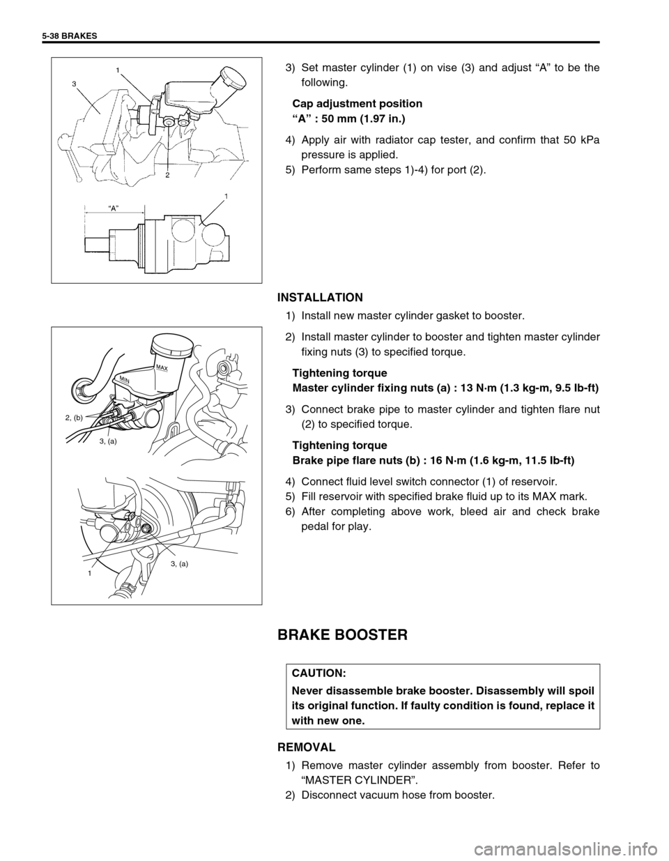
3) Set master cylinder (1) on vise (3) and adjust “A” to be the
following.
Cap adjustment position
“A” : 50 mm (1.97 in.)
4) Apply air with radiator cap tester, and confirm that 50 kPa
pressure is applied.
5) Perform same steps 1)-4) for port (2).
INSTALLATION
1) Install new master cylinder gasket to booster.
2) Install master cylinder to booster and tighten master cylinder
fixing nuts (3) to specified torque.
Tightening torque
Master cylinder fixing nuts (a) : 13 N·m (1.3 kg-m, 9.5 Ib-ft)
3) Connect brake pipe to master cylinder and tighten flare nut
(2) to specified torque.
Tightening torque
Brake pipe flare nuts (b) : 16 N·m (1.6 kg-m, 11.5 Ib-ft)
4) Connect fluid level switch connector (1) of reservoir.
5) Fill reservoir with specified brake fluid up to its MAX mark.
6) After completing above work, bleed air and check brake
pedal for play.
BRAKE BOOSTER
REMOVAL
1) Remove master cylinder assembly from booster. Refer to
“MASTER CYLINDER”.
2) Disconnect vacuum hose from booster.
3, (a)
1
3, (a) 2, (b)
CAUTION:
Never disassemble brake booster. Disassembly will spoil
its original function. If faulty condition is found, replace it
with new one.