Page 509 of 698

6A1-8 ENGINE MECHANICAL (M13 ENGINE)
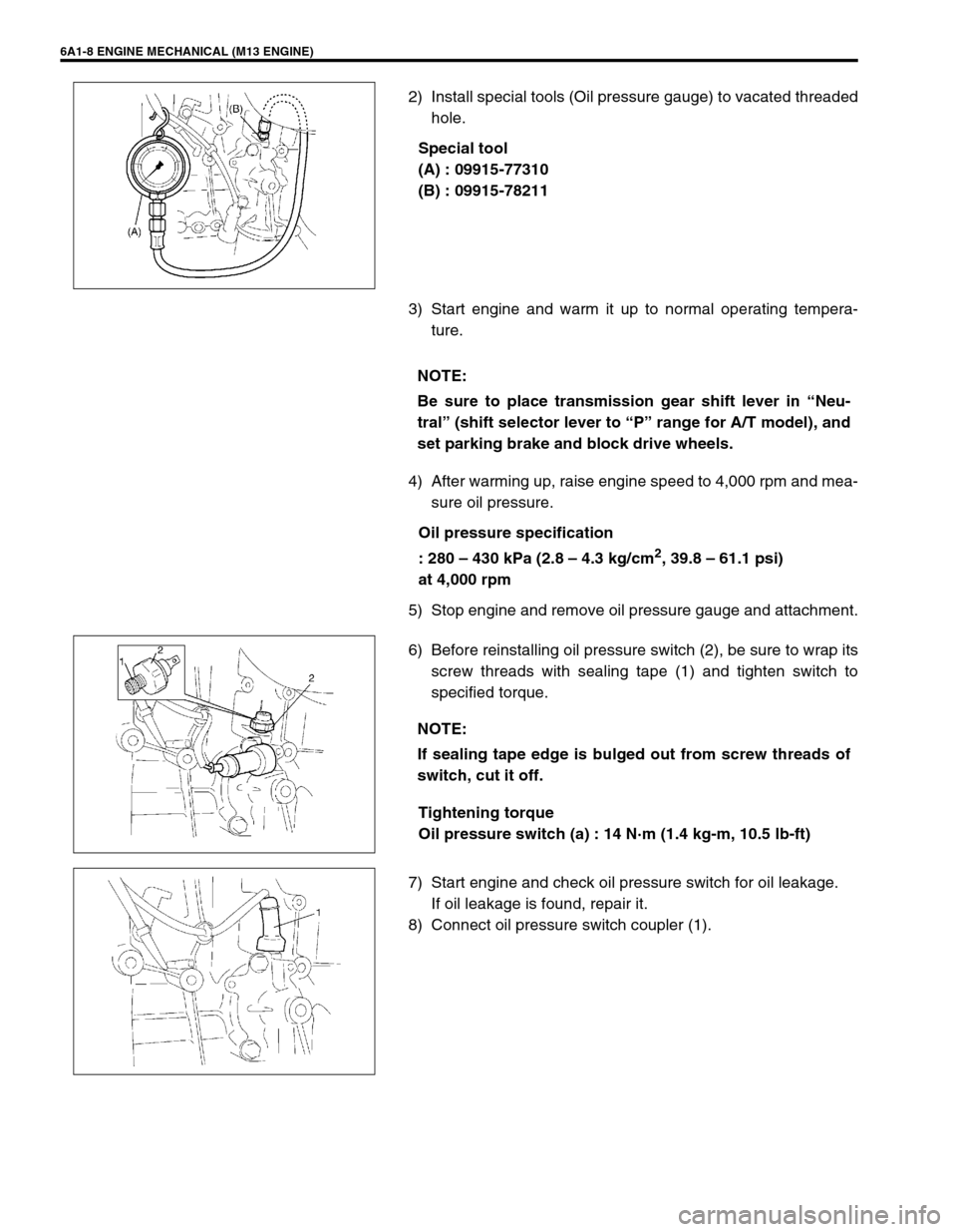
2) Install special tools (Oil pressure gauge) to vacated threaded
hole.
Special tool
(A) : 09915-77310
(B) : 09915-78211
3) Start engine and warm it up to normal operating tempera-
ture.
4) After warming up, raise engine speed to 4,000 rpm and mea-
sure oil pressure.
Oil pressure specification
: 280 – 430 kPa (2.8 – 4.3 kg/cm
2, 39.8 – 61.1 psi)
at 4,000 rpm
5) Stop engine and remove oil pressure gauge and attachment.
6) Before reinstalling oil pressure switch (2), be sure to wrap its
screw threads with sealing tape (1) and tighten switch to
specified torque.
Tightening torque
Oil pressure switch (a) : 14 N·m (1.4 kg-m, 10.5 lb-ft)
7) Start engine and check oil pressure switch for oil leakage.
If oil leakage is found, repair it.
8) Connect oil pressure switch coupler (1).
NOTE:
Be sure to place transmission gear shift lever in “Neu-
tral” (shift selector lever to “P” range for A/T model), and
set parking brake and block drive wheels.
NOTE:
If sealing tape edge is bulged out from screw threads of
switch, cut it off.
Page 514 of 698
ENGINE MECHANICAL (M13 ENGINE) 6A1-13
AIR CLEANER ASSEMBLY AND RESONATOR
REMOVAL
1) Disconnect negative cable at battery.
2) Disconnect IAT sensor coupler (1).
3) Disconnect breather hose (2) from cylinder head cover.
4) Remove air cleaner assembly (3), resonator (4) and their
hoses.
INSTALLATION
Reverse removal procedure for installation.
KNOCK SENSOR
Refer to “KNOCK SENSOR” in Section 6E.
CYLINDER HEAD COVER
REMOVAL
1) Disconnect negative cable at battery.
2) Remove air cleaner assembly, resonator and hoses by refer-
ring to “AIR CLEANER ASSEMBLY AND RESONATOR”.
3) Remove cylinder head upper cover (1).
4) Disconnect ignition coil couplers (1).
5) Remove ignition coil assemblies (2) with high-tension cord
(3).
Page 515 of 698
6A1-14 ENGINE MECHANICAL (M13 ENGINE)
6) Remove oil level gauge (1).
7) Disconnect PCV hose (2) from PCV valve (3) and release
harness clamp.
8) Remove cylinder head cover mounting bolts in such order as
indicated in figure.
9) Remove cylinder head cover (1) with cylinder head cover
gasket (2) and spark plug hole gasket (3).
INSTALLATION
1) Install new spark plug hole gaskets (1) and new cylinder
head cover gasket (2) to cylinder head cover (3) as shown in
figure.
2) Remove oil, old sealant, and dust from sealing surface on
cylinder head and cover. After cleaning, apply sealant “A” to
the following point.
Cylinder head gasket (1) sealing surface area (2) as shown.
“A” : Sealant 99000-31150
Page 516 of 698
ENGINE MECHANICAL (M13 ENGINE) 6A1-15
Timing chain cover (1) and cylinder head (2) matching sur-
face as shown.
“A” : Sealant 99000-31150
3) Install cylinder head cover to cylinder head.
4) Tighten bolts in such order as indicated in figure a little at a
time till they are tightened to specified torque.
Tightening torque
Cylinder head cover bolts (a) : 8 N·m (0.8 kg-m, 6.0 lb-ft)
5) Connect PCV hose (2) to PCV valve (1).
6) Install oil level gauge (3).
7) Install ignition coil assemblies with high-tension cord.
8) Connect ignition coil couplers and clamp harness securely.
9) Install cylinder head upper cover.
10) Install air cleaner assembly, resonator and hoses referring to
“AIR CLEANER ASSEMBLY AND RESONATOR”.
11) Connect negative cable at battery.NOTE:
When installing cylinder head cover, use care so that cyl-
inder head cover gasket or spark plug hole gaskets will
not get out of place or fall off.
Page 522 of 698
ENGINE MECHANICAL (M13 ENGINE) 6A1-21
4) Install exhaust manifold cover (1) .
5) Connect heated oxygen sensor coupler (2) and fit coupler to
bracket securely (if equipped).
6) Install heat insulator panel and front bumper with front grille
by referring to Section 9.
7) Connect negative cable at battery.
8) Check exhaust system for exhaust gas leakage.
OIL PAN AND OIL PUMP STRAINER
REMOVAL
1) Disconnect negative cable at battery.
2) Disconnect heated oxygen sensor coupler and detach it from
its stay.
3) Remove oil level gauge.
[A] : Sealant application amount 3. O-ring 8. Oil pan nut
“a” : 3 mm (0.12 in.) 4. Gasket 9. Oil pan bolt
“b” : 2 mm (0.08 in.) 5. Drain plug Tightening torque
1. Oil pan
: Apply sealant 99000-31150 to mating surface.6. Strainer bolt Do not reuse.
2. Strainer 7. Bracket bolt
Page 523 of 698
6A1-22 ENGINE MECHANICAL (M13 ENGINE)
4) Remove exhaust No.1 pipe (1).
5) Drain engine oil by removing drain plug.
6) Remove clutch housing (torque converter housing for A/T
vehicle) lower plate (1).
7) For 4WD vehicle, remove transfer referring to Section 7D.
8) Remove oil pan and then oil pump strainer (1) from cylinder
block.
CLEAN
Clean oil pump strainer screen (1).
Page 524 of 698

ENGINE MECHANICAL (M13 ENGINE) 6A1-23
Clean sealing surface on oil pan and cylinder block.
Remove oil, old sealant and dust from sealing surface.
INSTALLATION
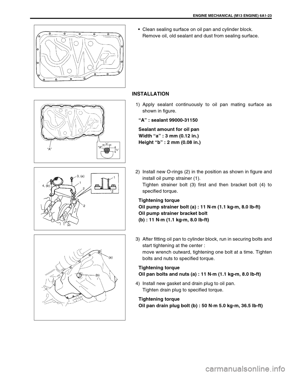
1) Apply sealant continuously to oil pan mating surface as
shown in figure.
“A” : sealant 99000-31150
Sealant amount for oil pan
Width “a” : 3 mm (0.12 in.)
Height “b” : 2 mm (0.08 in.)
2) Install new O-rings (2) in the position as shown in figure and
install oil pump strainer (1).
Tighten strainer bolt (3) first and then bracket bolt (4) to
specified torque.
Tightening torque
Oil pump strainer bolt (a) : 11 N·m (1.1 kg-m, 8.0 lb-ft)
Oil pump strainer bracket bolt
(b) : 11 N·m (1.1 kg-m, 8.0 lb-ft)
3) After fitting oil pan to cylinder block, run in securing bolts and
start tightening at the center :
move wrench outward, tightening one bolt at a time. Tighten
bolts and nuts to specified torque.
Tightening torque
Oil pan bolts and nuts (a) : 11 N·m (1.1 kg-m, 8.0 lb-ft)
4) Install new gasket and drain plug to oil pan.
Tighten drain plug to specified torque.
Tightening torque
Oil pan drain plug bolt (b) : 50 N·m 5.0 kg-m, 36.5 lb-ft)
Page 525 of 698
6A1-24 ENGINE MECHANICAL (M13 ENGINE)
5) Install clutch housing (torque converter housing for A/T vehi-
cle) lower plate (1).
6) For 4WD vehicle, install transfer by referring to Section 7D.
7) Install exhaust No.1 pipe (1).
Tighten bolts to specified torque.
Tightening torque
Exhaust No.1 pipe bolts (a) : 50 N·m 5.0 kg-m, 36.5 lb-ft)
8) Install oil level gauge.
9) Refill engine with engine oil referring to “ENGINE OIL
CHANGE” in Section 0B.
10) Verify that there is no engine oil leakage and exhaust gas
leakage at each connection.