Page 546 of 698

ENGINE MECHANICAL (M13 ENGINE) 6A1-45
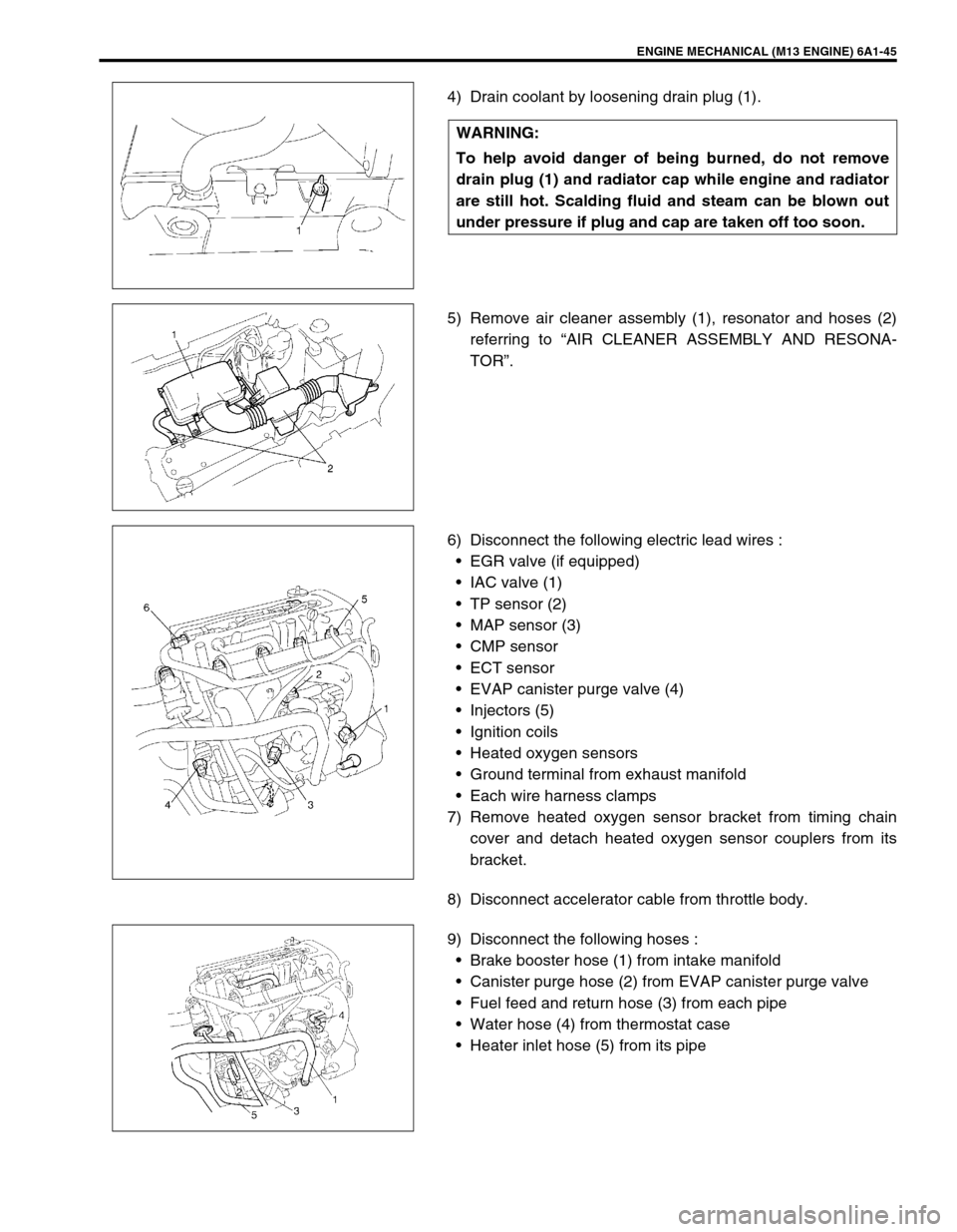
4) Drain coolant by loosening drain plug (1).
5) Remove air cleaner assembly (1), resonator and hoses (2)
referring to “AIR CLEANER ASSEMBLY AND RESONA-
TOR”.
6) Disconnect the following electric lead wires :
EGR valve (if equipped)
IAC valve (1)
TP sensor (2)
MAP sensor (3)
CMP sensor
ECT sensor
EVAP canister purge valve (4)
Injectors (5)
Ignition coils
Heated oxygen sensors
Ground terminal from exhaust manifold
Each wire harness clamps
7) Remove heated oxygen sensor bracket from timing chain
cover and detach heated oxygen sensor couplers from its
bracket.
8) Disconnect accelerator cable from throttle body.
9) Disconnect the following hoses :
Brake booster hose (1) from intake manifold
Canister purge hose (2) from EVAP canister purge valve
Fuel feed and return hose (3) from each pipe
Water hose (4) from thermostat case
Heater inlet hose (5) from its pipe WARNING:
To help avoid danger of being burned, do not remove
drain plug (1) and radiator cap while engine and radiator
are still hot. Scalding fluid and steam can be blown out
under pressure if plug and cap are taken off too soon.
Page 547 of 698

6A1-46 ENGINE MECHANICAL (M13 ENGINE)
10) Remove intake manifold stiffener (1).
11) Remove oil pan referring to “OIL PAN AND OIL PUMP
STRAINER”.
12) Remove cylinder head cover referring to “CYLINDER HEAD
COVER”.
13) Remove timing chain cover referring to “TIMING CHAIN
COVER”.
14) Remove timing chain referring to “TIMING CHAIN AND
CHAIN TENSIONER”.
15) Remove intake and exhaust camshafts referring to “CAM-
SHAFT, TAPPET AND SHIM”.
16) Loosen cylinder head bolts in such order as indicated in fig-
ure by using a 12 corner socket wrenches and remove them.
17) Check all around cylinder head for any other parts required
to be removed or disconnected and remove or disconnect
whatever necessary.
18) Remove exhaust manifold, if necessary, referring to
“EXHAUST MANIFOLD”.
19) Remove cylinder head with intake manifold and exhaust
manifold. Use lifting device, if necessary.
NOTE:
Don’t forget to remove bolt (M8) (1) as shown in figure.
Never reuse cylinder head bolts once disassembled it
due to plastic deformation tightening. Be sure to use
new cylinder head bolts when installing.
Page 548 of 698

ENGINE MECHANICAL (M13 ENGINE) 6A1-47
DISASSEMBLY
1) For ease in servicing cylinder head, remove intake manifold,
injectors and exhaust manifold from cylinder head.
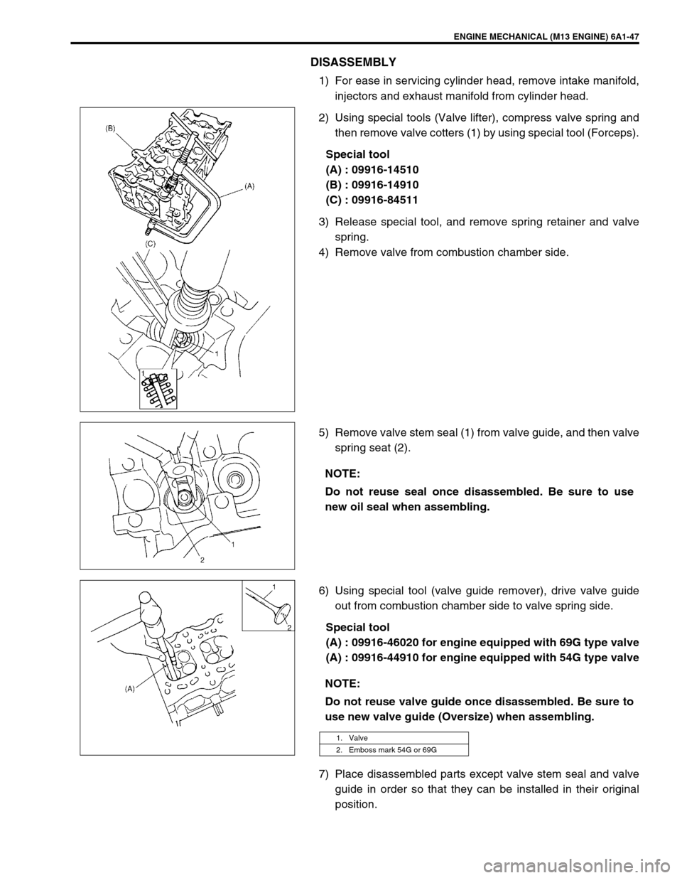
2) Using special tools (Valve lifter), compress valve spring and
then remove valve cotters (1) by using special tool (Forceps).
Special tool
(A) : 09916-14510
(B) : 09916-14910
(C) : 09916-84511
3) Release special tool, and remove spring retainer and valve
spring.
4) Remove valve from combustion chamber side.
5) Remove valve stem seal (1) from valve guide, and then valve
spring seat (2).
6) Using special tool (valve guide remover), drive valve guide
out from combustion chamber side to valve spring side.
Special tool
(A) : 09916-46020 for engine equipped with 69G type valve
(A) : 09916-44910 for engine equipped with 54G type valve
7) Place disassembled parts except valve stem seal and valve
guide in order so that they can be installed in their original
position.
NOTE:
Do not reuse seal once disassembled. Be sure to use
new oil seal when assembling.
NOTE:
Do not reuse valve guide once disassembled. Be sure to
use new valve guide (Oversize) when assembling.
1. Valve
2. Emboss mark 54G or 69G
Page 555 of 698

6A1-54 ENGINE MECHANICAL (M13 ENGINE)
3) Ream valve guide bore with special tool (6.0 mm reamer for
engine equipped with 69G type valve or 5.5 mm reamer for
engine equipped with 54G type valve). After reaming, clean
bore.
Special tool
(A) : 09916-34542
(B) : 09916-37810 (6 mm) for engine equipped with 69G
type valve
(B) : 09916-34550 (5.5 mm) for engine equipped with 54G
type valve
4) Install valve spring seat to cylinder head.
5) Install new valve stem seal (1) to valve guide.
After applying engine oil to seal and spindle of special tool
(Valve guide installer handle), fit oil seal to spindle, and then
install seal to valve guide by pushing special tool by hand.
After installing, check to be sure that seal is properly fixed to
valve guide.
Special tool
(A) : 09917-98221
(B) : 09916-57350 (For engine equipped with 69G type
valve)
(B) : 09916-58210 (For engine equipped with 54G type
valve)
6) Install valve to valve guide.
Before installing valve to valve guide, apply engine oil to
stem seal, valve guide bore and valve stem.
1. Valve
2. Emboss mark 54G or 69G
NOTE:
Do not reuse once-disassembled seal. Be sure to
install new seal.
When installing, never tap or hit special tool with a
hammer or else. Install seal to guide only by pushing
special tool by hand. Tapping or hitting special tool
may cause damage to seal.
2. Valve
3. Emboss mark 54G or 69G
Page 556 of 698

ENGINE MECHANICAL (M13 ENGINE) 6A1-55
7) Install valve spring and spring retainer.
Each valve spring has top end (large-pitch end (1)) and bot-
tom end (small-pitch end (2)). Be sure to position spring in
place with its bottom end (small-pitch end) facing the bottom
(valve spring seat side).
8) Using special tools (Valve lifter), compress valve spring and
fit two valve cotters (1) into groove in valve stem.
Special tool
(A) : 09916-14510
(B) : 09916-14910
(C) : 09916-84511
9) Install intake manifold, injectors and exhaust manifold to cyl-
inder head.
INSTALLATION
1) Clean mating surface of cylinder head and cylinder block.
Remove oil, old gasket and dust from mating surface.
2) Install knock pins (1) to cylinder block.
3) Install new cylinder head gasket (2) to cylinder block.
“TOP” mark provided on gasket comes to crankshaft pulley
side, facing up (toward cylinder head side).
4) Make sure that oil jet (venturi plug) (1) is installed and if it is,
that it is not clogged.
When installing it, be sure to tighten to specified torque.
Tightening torque
Venturi plug (a) : 5 N·m (0.5 kg-m, 3.5 lb-ft)
A : Valve spring retainer side
B : Valve spring seat side
NOTE:
When compressing the valve spring, be carefully to free
from damage in inside face of tappet installing hole.
Page 557 of 698

6A1-56 ENGINE MECHANICAL (M13 ENGINE)
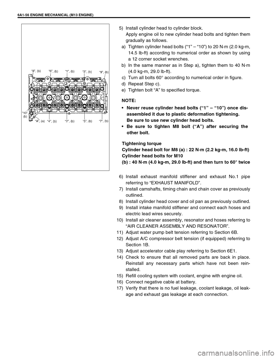
5) Install cylinder head to cylinder block.
Apply engine oil to new cylinder head bolts and tighten them
gradually as follows.
a) Tighten cylinder head bolts (“1” – “10”) to 20 N·m (2.0 kg-m,
14.5 lb-ft) according to numerical order as shown by using
a 12 corner socket wrenches.
b) In the same manner as in Step a), tighten them to 40 N·m
(4.0 kg-m, 29.0 lb-ft).
c) Turn all bolts 60° according to numerical order in figure.
d) Repeat Step c).
e) Tighten bolt “A” to specified torque.
Tightening torque
Cylinder head bolt for M8 (a) : 22 N·m (2.2 kg-m, 16.0 lb-ft)
Cylinder head bolts for M10
(b) : 40 N·m (4.0 kg-m, 29.0 lb-ft) and then turn to 60° twice
6) Install exhaust manifold stiffener and exhaust No.1 pipe
referring to “EXHAUST MANIFOLD”.
7) Install camshafts, timing chain and chain cover as previously
outlined.
8) Install cylinder head cover and oil pan as previously outlined.
9) Install intake manifold stiffener and connect each hoses and
electric lead wires securely.
10) Install air cleaner assembly, resonator and hoses referring to
“AIR CLEANER ASSEMBLY AND RESONATOR”.
11) Adjust water pump belt tension referring to Section 6B.
12) Adjust A/C compressor belt tension (if equipped) referring to
Section 1B.
13) Adjust accelerator cable play referring to Section 6E1.
14) Check to ensure that all removed parts are back in place.
Reinstall any necessary parts which have not been rein-
stalled.
15) Refill cooling system with coolant, engine with engine oil.
16) Connect negative cable at battery.
17) Verify that there is no fuel leakage, coolant leakage, oil leak-
age and exhaust gas leakage at each connection. NOTE:
Never reuse cylinder head bolts (“1” – “10”) once dis-
assembled it due to plastic deformation tightening.
Be sure to use new cylinder head bolts.
Be sure to tighten M8 bolt (“A”) after securing the
other bolt.
Page 558 of 698

ENGINE MECHANICAL (M13 ENGINE) 6A1-57
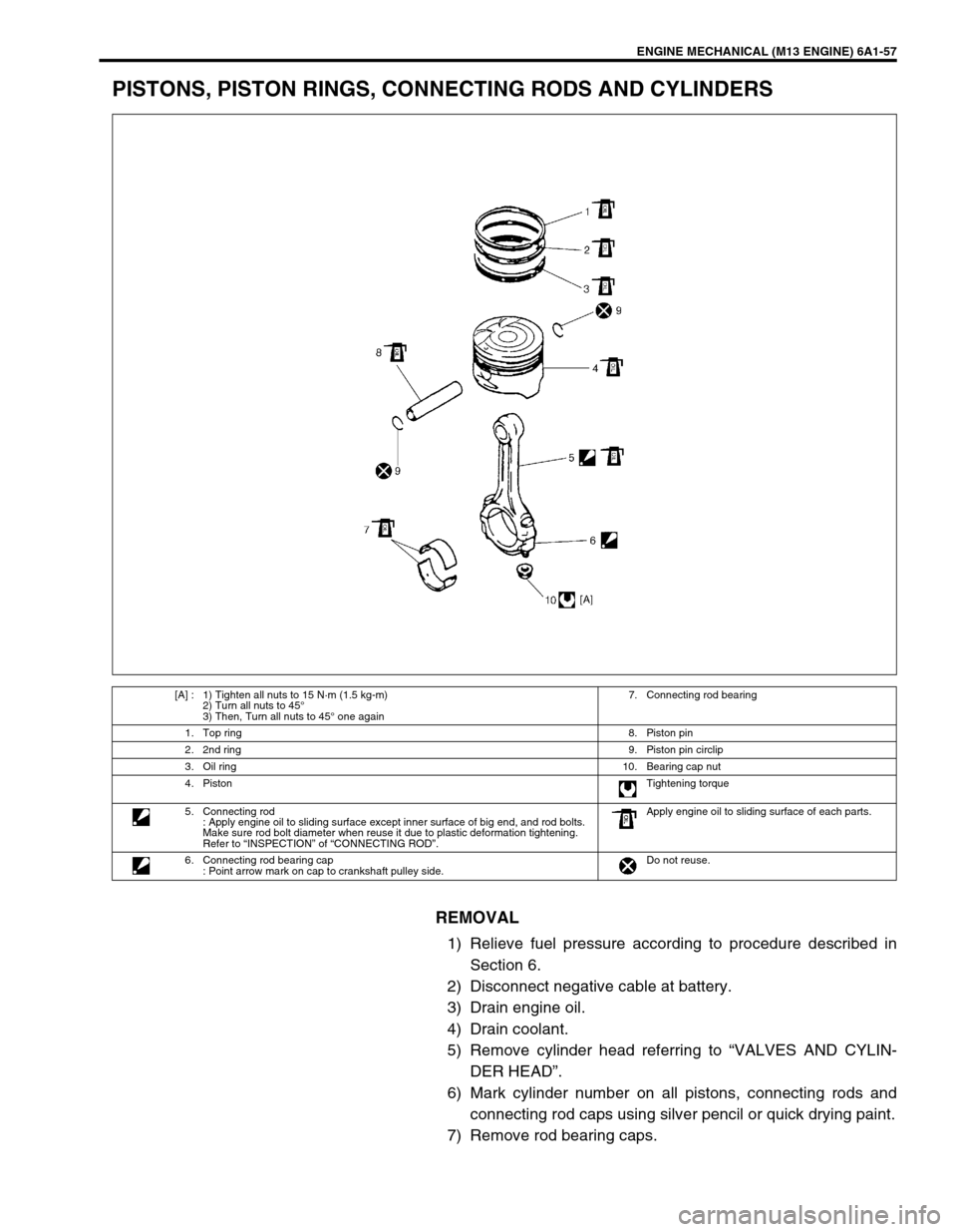
PISTONS, PISTON RINGS, CONNECTING RODS AND CYLINDERS
REMOVAL
1) Relieve fuel pressure according to procedure described in
Section 6.
2) Disconnect negative cable at battery.
3) Drain engine oil.
4) Drain coolant.
5) Remove cylinder head referring to “VALVES AND CYLIN-
DER HEAD”.
6) Mark cylinder number on all pistons, connecting rods and
connecting rod caps using silver pencil or quick drying paint.
7) Remove rod bearing caps.
[A] : 1) Tighten all nuts to 15 N·m (1.5 kg-m)
2) Turn all nuts to 45°
3) Then, Turn all nuts to 45° one again7. Connecting rod bearing
1. Top ring8. Piston pin
2. 2nd ring9. Piston pin circlip
3. Oil ring10. Bearing cap nut
4. PistonTightening torque
5. Connecting rod
: Apply engine oil to sliding surface except inner surface of big end, and rod bolts.
Make sure rod bolt diameter when reuse it due to plastic deformation tightening.
Refer to “INSPECTION” of “CONNECTING ROD”.Apply engine oil to sliding surface of each parts.
6. Connecting rod bearing cap
: Point arrow mark on cap to crankshaft pulley side.Do not reuse.
Page 559 of 698
6A1-58 ENGINE MECHANICAL (M13 ENGINE)
8) Install guide hose (1) over threads of rod bolts.
This prevents damage to bearing journal and rod bolt
threads when removing connecting rod.
9) Decarbonize top of cylinder bore before removing piston
from cylinder.
10) Push piston and connecting rod assembly out through the
top of cylinder bore.
DISASSEMBLY
1) Using piston ring expander, remove two compression rings
(Top and 2nd) and oil ring from piston.
2) Remove piston pin from connecting rod.
Ease out piston pin circlips (1), as shown.
Force piston pin out.
CLEANING
Decarbonize piston head and ring grooves, using a suitable tool.
INSPECTION
Cylinder
Inspect cylinder walls for scratches, roughness or ridges
which indicate excessive wear. If cylinder bore is very rough
or deeply scratched or ridged, rebore cylinder and use over-
size piston.