2000 SUZUKI SWIFT service
[x] Cancel search: servicePage 677 of 698

CRANKING SYSTEM 6G-5
NO-LOAD PERFORMANCE TEST
Connect battery and ammeter to starter as shown.
Check that starter rotates smoothly and steadily with pinion mov-
ing out. Check that ammeter indicates specified current.
Specified current (No-load performance test)
: 90 A MAX. at 11 V
ON-VEHICLE SERVICE
STARTING MOTOR
DISMOUNTING
1) Disconnect negative (–) battery lead at battery.
2) Disconnect magnetic switch lead wire (1) and battery cable (2) from starting motor terminals.
3) Remove starting motor mount bolt (3) and nut (4).
4) Remove starting motor (5).
REMOUNTING
Reverse the dismounting procedure.
Tightening torque
Starting motor battery cable nut (a) : 10 N·m (1.0 kg-m, 7.5 lb-ft)
Page 680 of 698

6G-8 CRANKING SYSTEM
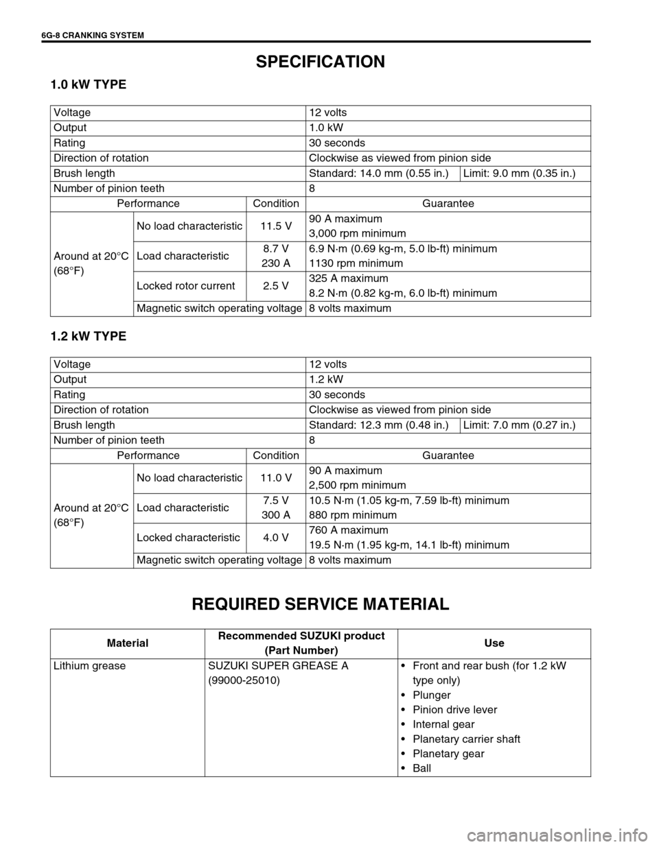
SPECIFICATION
1.0 kW TYPE
1.2 kW TYPE
REQUIRED SERVICE MATERIAL
Voltage 12 volts
Output 1.0 kW
Rating 30 seconds
Direction of rotation Clockwise as viewed from pinion side
Brush length Standard: 14.0 mm (0.55 in.) Limit: 9.0 mm (0.35 in.)
Number of pinion teeth 8
Performance Condition Guarantee
Around at 20°C
(68°F)No load characteristic 11.5 V90 A maximum
3,000 rpm minimum
Load characteristic8.7 V
230 A6.9 N·m (0.69 kg-m, 5.0 lb-ft) minimum
1130 rpm minimum
Locked rotor current 2.5 V325 A maximum
8.2 N·m (0.82 kg-m, 6.0 lb-ft) minimum
Magnetic switch operating voltage 8 volts maximum
Voltage 12 volts
Output 1.2 kW
Rating 30 seconds
Direction of rotation Clockwise as viewed from pinion side
Brush length Standard: 12.3 mm (0.48 in.) Limit: 7.0 mm (0.27 in.)
Number of pinion teeth 8
Performance Condition Guarantee
Around at 20°C
(68°F)No load characteristic 11.0 V90 A maximum
2,500 rpm minimum
Load characteristic7.5 V
300 A10.5 N·m (1.05 kg-m, 7.59 lb-ft) minimum
880 rpm minimum
Locked characteristic 4.0 V760 A maximum
19.5 N·m (1.95 kg-m, 14.1 lb-ft) minimum
Magnetic switch operating voltage 8 volts maximum
MaterialRecommended SUZUKI product
(Part Number)Use
Lithium grease SUZUKI SUPER GREASE A
(99000-25010)Front and rear bush (for 1.2 kW
type only)
Plunger
Pinion drive lever
Internal gear
Planetary carrier shaft
Planetary gear
Ball
Page 681 of 698

CHARGING SYSTEM 6H-1
6F1
6F2
6G
6K
7A
6H
7B1
7C1
7D
7E
7F
8A
8B
8C
8D
8E
9
10
10A
10B
SECTION 6H
CHARGING SYSTEM
CONTENTS
GENERAL DESCRIPTION .............................. 6H-2
BATTERY ..................................................... 6H-2
CARRIER AND HOLD-DOWN ................. 6H-2
ELECTROLYTE FREEZING .................... 6H-2
SULFATION ............................................. 6H-2
BUILT-IN INDICATOR (IF EQUIPPED) ... 6H-2
CARE OF BATTERY ................................ 6H-3
GENERATOR .............................................. 6H-4
DIAGNOSIS ..................................................... 6H-5
BATTERY ..................................................... 6H-5
VISUAL INSPECTION.............................. 6H-5
HYDROMETER TEST.............................. 6H-5
GENERATOR .............................................. 6H-6
CHARGING INDICATOR LAMP
OPERATION ............................................ 6H-6
UNDERCHARGED BATTERY ................. 6H-7
OVERCHARGED BATTERY.................... 6H-8ON-VEHICLE SERVICE .................................. 6H-9
BATTERY .................................................... 6H-9
JUMP STARTING IN CASE OF
EMERGENCY .......................................... 6H-9
DISMOUNTING...................................... 6H-10
HANDLING............................................. 6H-10
REMOUNTING....................................... 6H-10
GENERATOR ............................................ 6H-10
GENERATOR BELT .............................. 6H-10
DISMOUNTING AND REMOUNTING ... 6H-11
DISASSEMBLY AND REASSEMBLY .... 6H-11
INSPECTION ......................................... 6H-12
SPECIFICATION ........................................... 6H-14
BATTERY .................................................. 6H-14
GENERATOR ............................................ 6H-14
TIGHTENING TORQUE SPECIFICATION.... 6H-14
WARNING:
For vehicles equipped with Supplemental Restraint (Air Bag) System:
Service on and around the air bag system components or wiring must be performed only by an
authorized SUZUKI dealer. Refer to “Air Bag System Components and Wiring Location View” under
“General Description” in air bag system section in order to confirm whether you are performing ser-
vice on or near the air bag system components or wiring. Please observe all WARNINGS and “Ser-
vice Precautions” under “On-Vehicle Service” in air bag system section before performing service
on or around the air bag system components or wiring. Failure to follow WARNINGS could result in
unintentional activation of the system or could render the system inoperative. Either of these two
conditions may result in severe injury.
Technical service work must be started at least 90 seconds after the ignition switch is turned to the
“LOCK” position and the negative cable is disconnected from the battery. Otherwise, the system
may be activated by reserve energy in the Sensing and Diagnostic Module (SDM).
Page 684 of 698

6H-4 CHARGING SYSTEM
GENERATOR
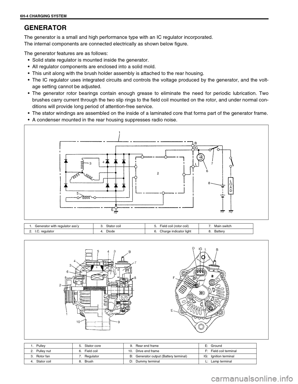
The generator is a small and high performance type with an IC regulator incorporated.
The internal components are connected electrically as shown below figure.
The generator features are as follows:
Solid state regulator is mounted inside the generator.
All regulator components are enclosed into a solid mold.
This unit along with the brush holder assembly is attached to the rear housing.
The IC regulator uses integrated circuits and controls the voltage produced by the generator, and the volt-
age setting cannot be adjusted.
The generator rotor bearings contain enough grease to eliminate the need for periodic lubrication. Two
brushes carry current through the two slip rings to the field coil mounted on the rotor, and under normal con-
ditions will provide long period of attention-free service.
The stator windings are assembled on the inside of a laminated core that forms part of the generator frame.
A condenser mounted in the rear housing suppresses radio noise.
1. Generator with regulator ass’y 3. Stator coil 5. Field coil (rotor coil) 7. Main switch
2. I.C. regulator 4. Diode 6. Charge indicator light 8. Battery
1. Pulley 5. Stator core 9. Rear end frame E: Ground
2. Pulley nut 6. Field coil 10. Drive end frame F: Field coil terminal
3. Rotor fan 7. Regulator B: Generator output (Battery terminal) IG: Ignition terminal
4. Stator coil 8. Brush D: Dummy terminal L: Lamp terminal
Page 685 of 698

CHARGING SYSTEM 6H-5
DIAGNOSIS
BATTERY
VISUAL INSPECTION
Check for obvious damage, such as cracked or broken case or cover, that could permit loss of electrolyte. If
obvious damage is noted, replace battery. Determine cause of damage and correct as needed.
HYDROMETER TEST
The direct method of checking the battery for state of charge is to
carry out a high rate discharge test, which involves a special pre-
cise voltmeter and an expensive instrument used in the service
shops, but not recommendable to the user of the vehicle.
At 20 °C of battery temperature (electrolyte temperature):
The battery is in FULLY CHARGED STATE if the electrolyte
S.G. is 1.280.
The battery is in HALF CHARGED STATE if the S.G. is
1.220.
The battery is in NEARLY DISCHARGED STATE if the S.G.
is 1.150 and is in danger of freezing.
As the S.G. varies with the temperature, if battery temperature is
not at 20°C (68°F), you have to correct your S.G. reading (taken
with your hydrometer) to the value at 20°C (68°F) and apply the
corrected S.G. value to the three-point guide stated value.
For the manner of correction, refer to the graph showing the rela-
tion between S.G. value and temperature at the left.
How to use the temperature-corrected state-of-charge graph
Suppose your S.G. reading is 1.28 and the battery temperature is
–5°C (23°F). Locate the intersection of the –5°C line and the 1.28
S.G. line.
The intersection is within the “A” zone (shaded area in the graph)
and that means CHARGED STATE.
To know how much the battery is charged, draw a line parallel to
the zone demarcation line and extend it to the right till it meets
with the percentage scale. In the present example, the line meets
at about 85% point on the percentage scale. Therefore, the bat-
tery is charged up to the 85% level.
Page 689 of 698

CHARGING SYSTEM 6H-9
ON-VEHICLE SERVICE
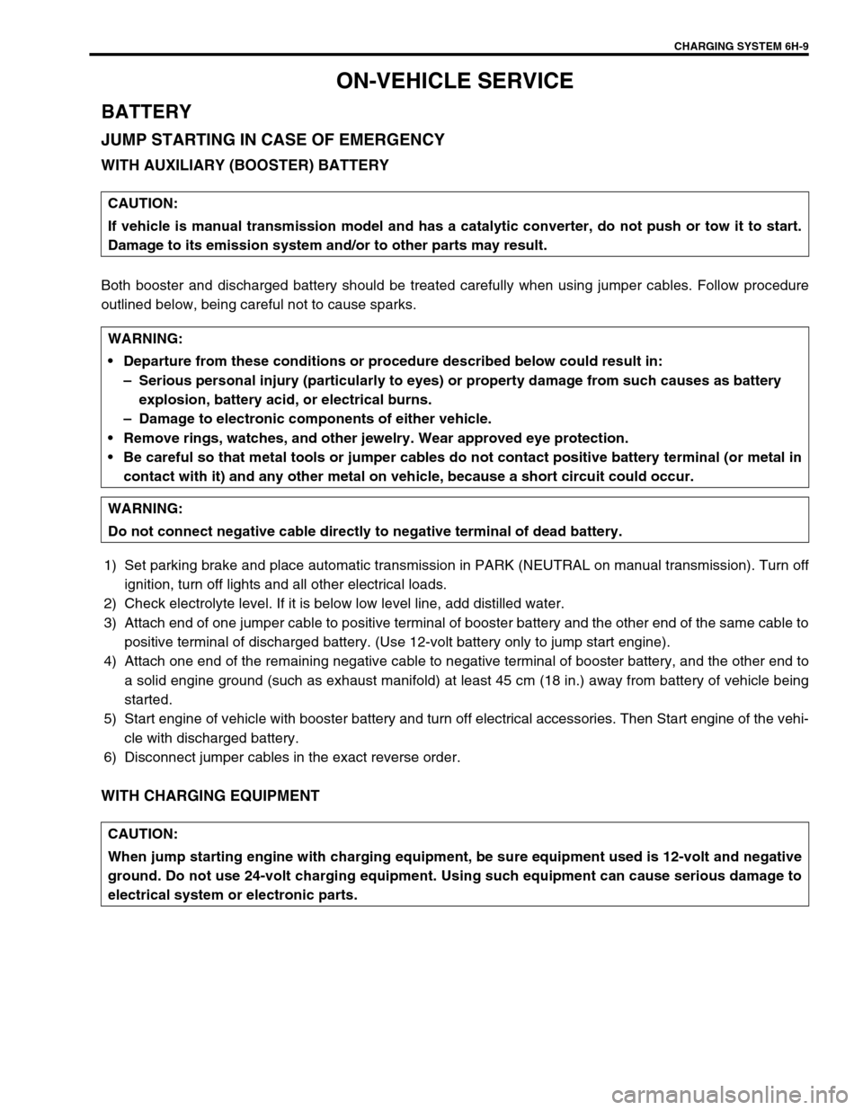
BATTERY
JUMP STARTING IN CASE OF EMERGENCY
WITH AUXILIARY (BOOSTER) BATTERY
Both booster and discharged battery should be treated carefully when using jumper cables. Follow procedure
outlined below, being careful not to cause sparks.
1) Set parking brake and place automatic transmission in PARK (NEUTRAL on manual transmission). Turn off
ignition, turn off lights and all other electrical loads.
2) Check electrolyte level. If it is below low level line, add distilled water.
3) Attach end of one jumper cable to positive terminal of booster battery and the other end of the same cable to
positive terminal of discharged battery. (Use 12-volt battery only to jump start engine).
4) Attach one end of the remaining negative cable to negative terminal of booster battery, and the other end to
a solid engine ground (such as exhaust manifold) at least 45 cm (18 in.) away from battery of vehicle being
started.
5) Start engine of vehicle with booster battery and turn off electrical accessories. Then Start engine of the vehi-
cle with discharged battery.
6) Disconnect jumper cables in the exact reverse order.
WITH CHARGING EQUIPMENT
CAUTION:
If vehicle is manual transmission model and has a catalytic converter, do not push or tow it to start.
Damage to its emission system and/or to other parts may result.
WARNING:
Departure from these conditions or procedure described below could result in:
–Serious personal injury (particularly to eyes) or property damage from such causes as battery
explosion, battery acid, or electrical burns.
–Damage to electronic components of either vehicle.
Remove rings, watches, and other jewelry. Wear approved eye protection.
Be careful so that metal tools or jumper cables do not contact positive battery terminal (or metal in
contact with it) and any other metal on vehicle, because a short circuit could occur.
WARNING:
Do not connect negative cable directly to negative terminal of dead battery.
CAUTION:
When jump starting engine with charging equipment, be sure equipment used is 12-volt and negative
ground. Do not use 24-volt charging equipment. Using such equipment can cause serious damage to
electrical system or electronic parts.
Page 693 of 698

CHARGING SYSTEM 6H-13
2) Using ohmmeter, check that there is no continuity between
coil leads and stator core. If there is continuity, replace sta-
tor.
BRUSH AND BRUSH HOLDER
Check each brush for wear by measuring its length as shown. If
brush is found worn down to service limit, replace brush.
Exposed brush length “a”
Standard: 10.5 mm (0.41 in.)
Limit: 1.5 mm (0.06 in.)
RECTIFIER
1) Using an ohmmeter, connect one tester probe to the “B” ter-
minal (1) and the other to each rectifier terminal (2).
2) Reverse the polarity of the tester probes and repeat step 1).
3) Check that one shows continuity and the other shows no
continuity.
If there is continuity, replace the rectifier.
4) Using an ohmmeter, connect one tester probe to each nega-
tive terminal (1) and the other to each rectifier terminal (2).
5) Reverse the polarity of the tester probes and repeat step 4).
6) Check that one shows continuity and the other shows no
continuity.
If there is continuity, replace the rectifier.
Page 695 of 698

EXHAUST SYSTEM 6K-1
6F1
6F2
6G
6H
7A
7A1
6K
7C1
7D
7E
7F
8A
8B
8C
8D
8E
9
10
10A
10B
SECTION 6K
EXHAUST SYSTEM
CONTENTS
GENERAL DESCRIPTION ...............................6K-2
MAINTENANCE................................................6K-2
ON-VEHICLE SERVICE ...................................6K-3EXHAUST MANIFOLD ................................. 6K-4
EXHAUST PIPE ............................................ 6K-4